Page is loading ...

© 2012 Tyco Electronics Corporation, a TE Connectivity Ltd. company
All Rights Reserved
*Trademark
TE Connectivity, TE connectivity (logo), and TE (logo) are trademarks. Other logos, product and/or company names may be trademarks of their respective owners.
1 of 4
Instruction Sheet
TOOLING ASSISTANCE CENTER
1-800-722-1111
PRODUCT INFORMATION
1-800-522-6752
This controlled document is subject to change.
For latest revision and Regional Customer Service,
visit our website at www.te.com
408-7300
Universal, Commercial, and .140
MATE-N-LOK* Contact and Housing
Selection Charts 28 NOV 12 Rev E
Stock thickness is 0.25 mm [.010 in.]; all others is 0.30 mm [.012 in.] Split pin contact
‡‡Use Hand Tool 91508-1 for wire size 20-18 AWG, Hand Tool 91506-1 for wire size 16-14,
Hand Tool 69710-1 and Die Set 583380-1 for 12 AWG, and Die Set 58380-2 for 10 AWG.
‡‡ Grounding pin Figure 1
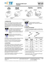
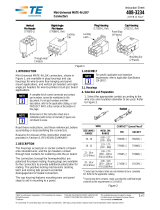
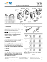
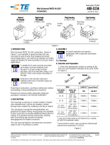
1. INTRODUCTION
This instruction sheet covers the use of MATE-N-LOK
contact and housing selection charts. MATE-N-LOK
contacts and housings are divided into three
categories: universal, commercial, and .140.
Read these instructions thoroughly to be sure the
selected contacts are compatible with the specified
housings, and the selected wire and application
tooling are compatible with the contacts.
Reasons for reissue of this document are provided in
Section 5, REVISION SUMMARY.
Socket Pin
Insulation Barrel
Insulation Barrel
Locator Slot Locator Slot
Wire Barrel
Wire Barrel
Wire Strip
Length
(See Note) Note: Strip length is 4.75 mm [.197 in.] for wire size range 30-14 AWG and 6.35 mm [.250 in.] for 12-10 AWG.
Wire Strip
Length
(See Note)
Universal MATE-N-LOK Contacts
Locking
Lance
Locking
Lance
WIRE UNIVERSAL MATE-N-LOK CONTACT HAND TOOLING
(Instruction Sheet)
SIZE (AWG)
RANGE INSULATION
DIAMETER (mm [in.]) LOOSE PIECE STRIP FORM
PIN SOCKET PIN SOCKET
30-26 0.81-1.45
[.032-.057] 770672-[ ] 770673-[ ] 350924-[ ] 350925-[ ] 58439-[ ]
(408-9591)
24-18 1.02-2.54
[.040-.100]
350690-[ ] 350689-[ ] 350561-[ ] 350570-[ ] 91510-1
408-9479)
350690-[ ] 640347-[ ] 350561-[ ] 350851-[ ]
350706-[ ] — 350699-[ ] —
20-14
1.52-3.30
[.060-.130]
350547-[ ] 350550-[ ] 350218-[ ] 350536-[ ] 91500-1
(408-9476)
350705-[ ] — 350687-[ ] —
350669-[ ] ‡ — 350654-[ ] ‡ —
3.30-5.08
[.130-.200]
350552-[ ] 350551-[ ] 350538-[ ] 350537-[ ] ‡‡91508-1 ‡‡
(408-8547)
‡‡91506-1 ‡‡
(408-8547)
350707-[ ] — 350700-[ ] —
18-14 3.30-5.08
[.130-.200] 350918-[ ] 350919-[ ] 350873-[ ] 350874-[ ] ‡‡91508-1 ‡‡
(408-8547)
‡‡91506-1 ‡‡
(408-8547)
12-10 5.08 [.200]
Max 640309-[ ] 640310-[ ] 350922-[ ] 350923-[ ] ‡‡69710-1 ‡‡
(Without Dies)
(408-2095)
and Die 58380-[ ]

408-7300
2 of 4
Rev E
‡ 2.92 mm [.115 in.] (max) each for applicator termination and 3.30 mm [.130 in.] (max) combined for hand tool termination
Figure 2
The contacts must be installed into the appropriate
housings and not switched between various categories
.
Dimensions in this instruction sheet are in metric
units [with U.S. customary units in brackets].
Figures are not drawn to scale.
NOTE
i
2. DESCRIPTION
2.1. Contacts
Universal pin and socket contacts (see Figure 1) are
available in five different wire ranges covering sizes
30 to 10 AWG with an insulation diameter range of
0.81 through 5.08 mm [.032 through .200 in.].
Commercial pin and socket contacts (see Figure 2)
are available for terminating wire sizes 30 to 14 AWG.
.
140 pin and socket .140 feature a stabilizing barrel and
are available for terminating wire sizes 20 to 10 AWG
.
The loose-piece contacts are designed for hand tool or
pneumatic tool applications. The strip-form contacts
are terminated using miniature quick-change
applicators used in the AMP-O-LECTRIC* machine,
AMPOMATOR* automatic lead-making machine, or
the standard and mini-single end lead machine (SELM
and Mini-SELM). Consult your Representative for
assistance in selecting the machine and applicator
that will best suit your needs.
2.2. Housings
.140 housings (see Figure 4) have a temperature
rating of -55 to +105°C [-65 to 221°F] and a maximum
voltage/current rating of 250 Vac at 28 amperes per
contact.
Universal housings (see Figure 5) have a temperature
rating of -55 to +105°C [-65 to 221°F] and a maximum
voltage/current rating of 600 Vac at 19 amperes per
contact. Pin and socket contacts can be used in either
plug or cap housings.
Commercial
housings (see Figure 6) have a temperature
rating of -55 to +105°C [-65 to 221°F] and a maximum
voltage/current rating of 250 Vac at 19 amperes per
contact.
Wire Barrel Insulation
Barrel
Locator
Slot
4.75 mm [.187 in.]
Wire Strip Length
Wire Barrel
Locator
Slot Insulation
Barrel
4.75 mm [.187 in.]
Wire Strip Length
Socket
Pin
Commercial MATE-N-LOK Contacts
Locking
Lance
Locking
Lance
WIRE COMMERCIAL MATE-N-LOK CONTACT HAND TOOLING
(Instruction Sheet
408-8547)
SIZE (AWG)
RANGE INSULATION
DIAMETER (mm [in.]) LOOSE PIECE STRIP FORM
PIN SOCKET PIN SOCKET
30-22 0.191 [.075]
(Max) 61174-[ ] 61173-[ ] 350079-[ ]0350078-[ ]091515-1
24-18 1.09-1.91
[.043-.075] 60618-[ ] 60617-[ ] 61116-[ ] 61114-[ ] 91528-1
24-20 1.52-2.54
[.060-.100] 60618-[ ] 60617-[ ] 61116-[ ] 61114-[ ] 91512-1
— 61473-[ ] — 61115-[ ]
20-14 2.54-3.30
[.100-.130] 60620-[ ] 60619-[ ] 61118-[ ] 61117-[ ] 91504-1
(1) 18 and (1) 16
or (2) 18 2.92 [.115] (Max) and
3.30 [.130] (Max) ‡ 350639-[ ]0350638-[ ]0350558-[ ]0350557-[ ]091504-1

408-7300
3 of 4
Rev E
Figure 3
3. SELECTION
Determine the housing type (universal, commercial, or
.140) to be assembled. Refer to the listings of
compatible contacts, and select the contact type and
recommended wire size. Make contact selections from
Figures 1, 2, and 3. Make housing selections from
Figures 4, 5, and 6. Select contacts as follows:
1. Determine the appropriate wire size to be used
with the contact according to Column 1. Make
certain the wire insulation diameter is within the
range specified in Column 2.
2. Columns 3, 4, 5, and 6 indicate the appropriate
loose-piece and strip-form contacts for the selected
wire size. Check that these base part numbers
correspond with those on the package or reel.
3. Column 7 indicates the appropriate hand tooling
to be used to crimp loose-piece contacts. Machines
for strip-form contacts are listed in Paragraph 2.1.
4. CONTACT INSERTION AND EXTRACTION
The following tools are recommended:
Contact Type Insertion Tool Extraction Tool
Universal 91002-1 1804030-1
Commercial 455830-1 305183 or 465644
.140 None 318845-1
Not necessary because of the large wire size
To insert a contact into a housing:
1. Place the tweezer-shaped tool over the wire with
the tool insertion tip behind the contact insulation
barrel.
2. Insert the contact into the housing cavity until the
contact locking lance is fully seated.
To extract a contact from a housing:
1. Gently push the wire of the contact to be
removed.
2. From the mating face of the housing, slide the
tube-shaped tool into the contact cavity of the
contact to be removed until the locking lances are
encased.
3. Lighted push the tool while pulling the wire.
Mating
Portion
Wire
Barrel
Insulation
Barrel
Locator Slot
6.35 mm [.250 in.]
Wire Strip Length
Mating
Portion
Socket Crimped Pin
.140 MATE-N-LOK Contacts
Locking
Lance
Locking
Lance
Stabilizer
WIRE .140 MATE-N-LOK CONTACT HAND TOOLING
(Instruction Sheet)
SIZE (AWG)
RANGE INSULATION
DIAMETER (mm [in.]) LOOSE PIECE STRIP FORM
PIN SOCKET PIN SOCKET
20-14 2.54-4.57
[.100-.180]
350389-[ ] 350388-[ ] 061627-[ ] 061626-[ ] 90247-1 (408-7434)
14-10 350391-[ ] 350390-[ ] 350201-[ ] 350200-[ ] 69710-1 (Without Dies) (408-2095)
and Die 58373-[ ] or 58374-[ ]
.140 MATE-N-LOK HOUSING
NO. OF CIRCUITS PLUG CAP
2 350344-[ ] 350345-[ ]
3 350346-[ ] 350347-[ ]
4 480510-[ ] 480512-[ ]
9480585-[ ] 480586-[ ]
480672-[ ] 480673-[ ]
Plug (Socket) Cap (Pin)
.140 MATE-N-LOK Housings

408-7300
4 of 4
Rev E
Figure 4
Figure 5
†Housing accepts double-wire applications where individual insulation
diameters do not exceed 2.92 mm [.115 in.].
Figure 6
5. REVISION SUMMARY
Since the previous version of this document, the
following changes were made:
•Corrected part number in Figure 1.
UNIVERSAL MATE-N-LOK HOUSING
NO. OF
CIRCUITS PLUG CAP UL 94
MATERIAL
RATING
1350867-[ ] 770421-1 V-2
350865-[ ] 350866-[ ] V-0
2480698-[ ] 480699-[ ] V-2
350777-[ ] 350778-[ ] V-0
3480700-[ ] 480701-[ ] V-2
350766-[ ] 350767-[ ] V-0
4480702-[ ] 480703-[ ] V-2
350799-[ ] 350780-[ ] V-0
5480763-[ ] 480764-[ ] V-2
350809-[ ] 350810-[ ] V-0
6
480704-[ ] 480705-[ ] V-2
350715-[ ] 350781-[ ] V-0
640585-[ ] — V-2
640581-[ ] — V-0
8640586-[ ] — V-2
640582-[ ] — V-0
9480706-[ ] 480707-[ ] V-2
350720-[ ] 350782-[ ] V-0
12 480708-[ ] 480709-[ ] V-2
350735-[ ] 350783-[ ] V-0
15 480710-[ ] 480711-[ ] V-2
350736-[ ] 350784-[ ] V-0
Plug (Socket) Cap (Pin)
Universal MATE-N-LOK Housings
COMMERCIAL MATE-N-LOK HOUSING
NO. OF CIRCUITS PLUG CAP
1480349-[ ]†480350-[ ]†
480349-[ ]†480351-[ ]†
2 480318-[ ] † 480319-[ ] †
3480303-[ ] † 480305-[ ] †
480304-[ ] † 480305-[ ] †
4480424-[ ] † 480426-[ ] †
480425-[ ] † 480426-[ ] †
6
480270-[ ] † 480271-[ ]†
480273-[ ] † 480276-[ ] †
480270-[ ] † 480340-[ ]†
480270-[ ] † —
8480283-[ ] † 480284-[ ]†
480283-[ ] † 480345-[ ]†
9 480274-[ ] † 480277-[ ] †
10 480285-[ ] † 480286-[ ]†
480285-[ ] † 480339-[ ]†
12 480275-[ ] † 480278-[ ] †
480287-[ ] † 480288-[ ]†
15 480323-[ ] † 480324-[ ] †
16 480438-[ ] † 480439-[ ]†
Plug (Socket) Cap (Pin)
Commercial MATE-N-LOK Housings
/

