Page is loading ...

Copyright © 2019 by Hexagon agriculture. All rights reserved.

User manual - Machine Automation Solution - V3R003 2 / 102
Summary
1 Introduction 4
2 Safety instructions 5
2.1 Allowed usage 5
2.2 Use risks 5
2.3 Electromagnetic compatibility 5
3 Displays overview 7
3.1 Overview of the HxGN AgrOn Ti10 7
3.1.1 System components 7
3.1.2 View s 7
3.1.3 Product identification 8
3.1.4 CAN connector pinout 8
4 Equipment's installation 10
4.1 Displays's fixation 10
4.2 SIM card installation 10
4.3 Antenna installation 11
5 Running display for the first time 13
5.1 Starting the device 13
5.2 Shutting down the monitor 13
6 Job section 14
6.1 Selecting a job section 14
6.2 Inserting a job section 15
6.2.1 New job section in conventional mode 15
6.2.2 New job section on fast start mode 15
6.3 Removing a job section 16
7 Operation screen 17
7.1 Upper bar 17
7.1.1 Alerts 17
7.2 Connectivity information 22
7.3 Lightbar 23
7.4 Information configuration 23
7.5 Main menu 24
7.5.1 Guide 24
7.5.2 Visualization 24
7.5.3 Tools 25
7.5.4 Configuration menu 29
7.6 Context bar 30
8 GNSS 31
8.1 NTRIP server 35
8.1.1 NTRIP status 35
8.1.2 NTRIP Server 36
8.2 NMEA output 37
8.3 Operation 38
9 Vehicle 40
9.1 Inserting a new vehicle 40
9.2 Editing the vehicle 41
9.3 Removing the vehicle 42
10 Implement 43
10.1 Inserting a new implement 43
10.2 Editing the implement 44
10.3 Removing the implement 44
10.4 Testing the implement 44
11 Guidance 46
11.1 Settings 46
11.1.1 Parameters 46
11.1.2 Wayline settings 48
11.1.3 Reverse detector 53
11.1.4 Odometer 54
11.1.5 Perimeter 54
11.1.6 Apply outside map 55
11.2 Operation 55
11.2.1 Creating a guide line 55
11.2.2 Working w ith an active guide 60
11.2.3 Managing guides 63
12 Files 70
12.1 Exporting data 70
12.1.1 Exporting an operation map 70
12.1.2 Exporting a prescription map 71
12.1.3 Exporting guides 72

User manual - Machine Automation Solution - V3R003 3 / 102
12.1.4 Exporting markers 72
12.1.5 Settings 72
12.1.6 Exporting pending files 73
12.2 Importing data 73
12.3 Deleting data 74
13 System settings 75
13.1 Modo normal 75
13.1.1 About 75
13.1.2 Language and region 79
13.1.3 System mode 79
13.1.4 Support mode 80
13.1.5 Network troubleshooting 80
13.2 Advanced mode 81
13.2.1 Change passw ord 81
13.2.2 Logging 82
13.2.3 Network 83
13.2.4 Activation 84
13.2.5 Firmw are update 85
13.2.6 External settings 86
13.2.7 Data synchronization 87
13.2.8 RFIDs tags list 87
13.2.9 PLC 89
14 Assistance and remote acess 94
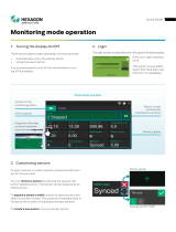
14.1 Visualization mode 94
14.2 Operation mode 94
15 Technical features 96
15.1 Display Ti10 96
16 FCC statement (applicable only in the USA) 98
17 Compliance with European Directive 1999/5/EC (R&TTE) 99
18 Problems and solutions 100
19 Glossary 101
20 Warranty certificate 102

User manual - Machine Automation Solution - V3R003 4 / 102
1. Introduction
This manual contains important information on how to install, configure, and use the display. To access the complete manual with
all other display features and products, download the document version available from the Hexagon Agriculture website support
(https://hexagonagriculture.com/support/manuals).
Initials informations:
·Carefully read this user manual before turning the display on;
·To ensure your safety, observe the instructions contained in the User Manual and the Safety Manual issued by the
manufacturer of the farming machinery;
·The images in this manual are purely illustrative. Screens and visual elements may differ from the actual items.
The symbols used in this manual have the following meanings:
Warning Indicates a potentially hazardous situation or misuse which, if unavoided, may result in minor to
moderate injury, material loss, financial loss and/or environmental loss.
Danger Indicates an imminently hazardous situation which, if unavoided, may result in serious injury or
death.
Important Important information that must be observed so that display is used in a technically correct and
efficient manner.

User manual - Machine Automation Solution - V3R003 5 / 102
2. Safety instructions
·Allowed usage
·Use risks
·Electromagnetic compatibility
2.1 Allowed usage
The following instructions aim to inform users about the inherent risks to display operation as well as how to avoid them.
Warning Only use the display computer on vehicles with farming purposes such as tractors, sprayers,
planters, fertilizer applicators, subsoilers, trucks, among others.
It is not allowed:
·Using outside the restrictions imposed in this manual;
·Opening the device with tools, except with technical supportʼs written permission;
·Modifying or altering the product;
·Using the display with obvious damage or defects;
·Using the display with accessories from other manufacturers without approval.
Warning The display must not be used without the user being aware of the correct product usage. Its
incorrect usage may result in personal injury, breakdown, and damage.
Danger Unauthorized modification of the vehicle for mounting or installing the display may alter the
operation and safety of the agriculture machinery.
Warning Verify the integrity of the results of the display's measurements after a fall or misuse,
transport, modification, or when stored for long periods of time.
2.2 Use risks
·Use of the display is not recommended during thunderstorms due to the risk of being struck by lighting;
·Keep a safe distance from electrical installations and components;
·In case the product will not be used for a long time, it is recommended to disconnect all components and
cables;
·To clean the displayʼs monitor, use a soft cloth moistened with 50% isopropyl alcohol.
Incorrect disposal of the display may cause the following problems:
·Release of poisonous gases in case of polymer burning;
·Improper product use, resulting in serious physical harm;
·Contamination of the environment.
Warning The display must not be mixed with household waste. It must be disposed of in accordance
with regulations in force in the country of use.
2.3 Electromagnetic compatibility
Electromagnetic compatibility refers to the productʼs ability to function properly in an environment with electromagnetic
radiation and electrostatic discharge, without causing electromagnetic disturbances to other devices.

User manual - Machine Automation Solution - V3R003 6 / 102
Warning Electromagnetic radiation may cause disturbances in other devices. Although this product
fully meets the strictest regulations and standards in force, Hexagon Agriculture cannot
completely exclude the possibility of interference with other devices.
There is a risk that interference may occur in other devices if the instrument is used with accessories from other
manufacturers such as computers, laptops, radios, non-standard cables, external batteries, etc.
Recommendations:
·Only use devices and accessories recommended by Hexagon Agriculture. When used with this instrument,
such accessories meet the strictest requirements of the regulations and standards in force;
·Consider the information on electromagnetic compatibility provided by computer and transceiver radios
during their use;
·Monitor measurement results when operating in areas with disturbances caused by electromagnetic radiation, as
these may lead to incorrect results. Although this product fully meets the strictest regulations and standards in
force, Hexagon Agriculture cannot completely exclude the possibility of interference in the instrument
caused by intense electromagnetic radiation emitted, for example, by radio transmitters, generators,
electric cables, etc.
·Always connect both ends of the cables during use. If the instrument is used with cables connected only to one
end, the permissible level of electromagnetic radiation may be exceeded and the correct operation of the instrument
may be affected;
·Do not operate the product with radio devices or mobile phones near fuel stations, chemical facilities, areas
with explosion hazards, medical devices, or aircraft. The electromagnetic fields caused by using the product with
radio devices or mobile phone may cause interference in other devices, facilities, aircraft, and medical instruments
such as heart rate regulators or hearing aids. Electromagnetic radiation might even affect humans and animals.
Although the product meets the regulations and standards in force, Hexagon Agriculture cannot completely exclude
the possibility of other devices being disturbed or people and animals being affected.

User manual - Machine Automation Solution - V3R003 7 / 102
3. Displays overview
·Overview display Ti10
3.1 Overview of the HxGN AgrOn Ti10
The HxGN AgrOn Ti10 is a complete precision farming guidance system with the following functions:
Figure - General application
3.1.1 System components
1. Display's monitor
2. GNSS antenna
3. Antenna suport
4. Antenna cable
5. Power cable
6. Arm - mounting bracket
7. Clamp - mounting bracket
8. Flashdrive
9. Documentation Figure - System components
3.1.2 Views
Warning The display was designed to be used with the touch of your fingers on the screen. Do not
operate with sharp objects such as pens or screwdrivers as this may damage and affect the
warranty of your product.
1. 10,1-inch color touchscreen
2. Secondary mobile data connection
3. Connection for mobile data
4. Connecting the GNSS antenna
5. Mounting bracket
6. SIM card slot
7. Wi-Fi antenna connection
8. Power button

User manual - Machine Automation Solution - V3R003 8 / 102
9. USB interface
10. Connector A
11. Connector C
12. Connector B
See page 12 for more information on the connectors.
Figure - Connector identification
3.1.3 Product identification
The product type (model) and serial number are indicated on a label on the back of the display. Record the type and serial
number in your manual and inform them when contacting technical support.
Figure - Product identification
Important You can also check your deviceʼs serial number accessing the Configuration menu – System
settings – About.
3.1.4 CAN connector pinout

User manual - Machine Automation Solution - V3R003 9 / 102

User manual - Machine Automation Solution - V3R003 10 / 102
4. Equipment's installation
·Display's fixation
·SIM Card installation
·Antenna installation
4.1 Displays's fixation
Warning The display installation must be performed by a qualified technician. Read the safety
instructions before performing the installation steps.
Warning Do not mount the display where it can be struck by an airbag.
Ti10 display fixation
Choose an appropriate location for securing the display monitor within reach of the operator while seated in a normal
operating position and in front of the operatorʼs field of vision.
Figure - Display installation
Warning Do not mount the display where it can be struck by an airbag.
To perform the installation, proceed as follows:
1. Mount the clamp to the desired location in the vehicle. To mount the clamp, wrap the bow around the tube,
insert the base, and fasten with hex nuts. Use a socket wrench for better tightening;
2. Connect the clamp ball and the monitor to the mounting arm, firmly securing using the handle;
3. Position the assembly in a location visible to the operator and check if it is firm and secure;
4. Connect the power cable to a battery or to a location indicated by the vehicle manufacturer and connect the
other end to the back of the display;
5. Connect the horn cable to the input/output connector.
4.2 SIM card installation
Warning The viability of installing the SIM card should be checked by a qualified technician for the Ti10
display.
To enable remote communication on systems equipped with an internal modem, a SIM card is required.
Important Only required in Wi-Fi + Mobile network version.

User manual - Machine Automation Solution - V3R003 11 / 102
To install the SIM card, proceed as follows:
1. On the back of the display, remove the four screws as shown in the
figure. Use the lowered space to make it easier to open the lid;
Figure - Opening the lid
2. Pull the insert down and open to a 90-degree angle;
Figure - SIM card housing step 1
3. Insert the SIM card into the slot, ensuring its proper positioning;
4. Close the opening and push up until you hear the locking sound;
Figure - SIM card housing step 2
5. Put the back lid on and screw the removed screws.
4.3 Antenna installation
Warning
·The display antenna must be mounted on the roof of the vehicle, preferably front and center
on the flat part of the roof;
·The antenna must be mounted horizontally and must not me tilted in order to ensure the
best GNSS signal reception;
·It is necessary to keep the antenna as far away as possible from obstacles in order to
ensure that the signal is received in all directions;
·A clear view of the sky to the horizon in all directions is recommended for the ideal
reception of satellites, as obstacles close to the antenna prevent the reception of signals;
·Keep the GNSS antenna as far away from the radio antennas as possible;
·If the antennas are installed too close to each other there may be interaction between the
antennas and a consequent loss of sensitivity.
To install the antenna, proceed as follows:
1. Clean and dry the roof of the vehicle to prepare the installation. We recommend isopropyl alcohol;
2. Check if the installation area on the roof is clean and dry;
3. Attach the GNSS antenna. It has magnets that attach to the vehicleʼs metallic roof. In case it is not metallic,
use a metal bracket for fastening, using double-sided tapes on the back of the holder. Remove the tapeʼs
plastic protection and make it adhere to the roof of the vehicle;
4. Connect the antenna cable to the back of the display. The cable cannot be cut, twisted, or excessively bent,
as its performance may be degraded causing the system to fail.

User manual - Machine Automation Solution - V3R003 12 / 102
Figure - Ti10 monitor display antenna installation

User manual - Machine Automation Solution - V3R003 13 / 102
5. Running display for the first time
Warning We recommend starting the vehicle before turning the display on.
5.1 Starting the device
To turn the monitor on, proceed as follows:
1. Press the On Button on the front panel of the display for one second;
2. The display will show the screen for selecting Language, Time Zone, and Theme;
3. Enter the desired settings and confirm;
4. If operating in the quick launch mode, when starting your display for the first time, the new work session setup
wizard will show. Go to topic New job section on fast start mode;
5. If operating in the conventional launch mode, go to next topic Job section.
Important
The fast start mode is only available for the display with solely and exclusively the Guidance
activated. To enable or disable this function, select the Fast mode ON/OFF option located on
the right side of the work session list. The display will always start in the same startup mode
it was operating in when it was turned off (quick launch mode or conventional launch mode).
Figure - Language and time zone selection
5.2 Shutting down the monitor
To shutdown the monitor of your display, proceed as follows:
1. Press the Off button on the front of the module;
2. A confirmation message will be displayed;
3. Confirm the operation by selecting Yes;
4. Wait for the screen to turn off.
Warning Do not remove the power source without the screen turning off completely.

User manual - Machine Automation Solution - V3R003 14 / 102
6. Job section
A job section consists of the combination of various information that characterize a performed job, such as the performed
activity, in which farm, in which field, etc.
In order to operate the display, there must always be a running work session, which may have been previously created or
completely new. For this reason, when the device is turned on, the system directs the user to the Job section
management screen.
Important The Job section management may also be accessed at any time by the used through the
Configuration menu.
Job section in conventional mode
From this screen one may select, delete, or create a new job section.
Figure - Conventional job section
Job section on fast start mode
The job section on fast start mode is only available for the displays with solely and exclusively the Guidance activated. To
enable or disable this function, select the Fast mode ON/OFF option located on the right side of the job section list. The
display will always start in the same startup mode it was operating in when it was turned off (fast start mode or
conventional mode).
From this screen one may select, delete, or create a new job section, enable or disable the fast start mode, or view the
settings of the last implement used.
Figure - Job section on fast start mode
6.1 Selecting a job section
Job section selection is the same for both launch modes. See topic Job section.
To select a job section, proceed as follows:
1. Select a Job section among those presented on the screen;
2. Press OK to start the operation.
Important Regardless of the Job section selected from the list, display will always use the settings for
the last implement used. To check the current values, on fast start mode they are displayed in
the indicator boxes on the right side of the screen.

User manual - Machine Automation Solution - V3R003 15 / 102
6.2 Inserting a job section
The way to create a new job section will depend on the type of startup:
·If operating in conventional mode, go to next topic New job section in conventional mode,
·If operating in fast mode, go to topic New section on fast start mode.
6.2.1 New job section in conventional mode
To create a new job section in conventional mode, proceed as follows:
1. On the Job section screen, select option New;
2. A message will be displayed informing the necessary input fields for creating a new job section;
3. Click OK to confirm reading the message;
4. The list of farms is presented;
5. Select a farm from the list or select New to insert a new farm;
6. Enter the farm name and select OK to confirm;
7. Confirm the name presented on the list and click OK to select;
8. The list of fields is presented;
9. Select a field from the list or select New to insert a new field;
10. Enter the field name and select OK to confirm;
11. Confirm the name presented on the list and click OK to select;
12. The list of activities is presented;
13. Select an activity from the list or select New to insert a new activity;
14. Enter the activity name and select OK to confirm;
15. Confirm the name presented on the list and click OK to select;
16. The new job section is created.
Important The Farm, Field, and Activity fields only allow names with at most twelve characters. There
cannot be work sessions with the same name (Farm, Field, and Activity).
Warning When the Open last session when starting box is activated, the work session screen will no
longer be displayed when the device is started. Instead, it will start directly at the operation
window for the last used work session.
6.2.2 New job section on fast start mode
To create a new job section on fast start mode, proceed as follows:
1. Click on New;
2. On the Implement and Vehicle screen, insert the implementʼs width and the distance from the vehicleʼs
antenna to the implement;
3. Confirm the operation selecting the Save option;
4. A message informing that the new job section has been created will be displayed;
5. Confirm you have read the message by selecting OK;
6. The operation screen will be displayed.

User manual - Machine Automation Solution - V3R003 16 / 102
Figure - lmplement and vehicle
6.3 Removing a job section
To remove a job section on fast start mode, proceed as follows:
1. Select a Job section among those presented on the screen;
2. Select option Delete;
3. A confirmation message will be displayed;
4. Confirm the operation by selecting Yes;
5. The Job section is deleted.
Important The system will not allow deleting the Job section currently in use.

User manual - Machine Automation Solution - V3R003 17 / 102
7. Operation screen
The operation consists of the main screen where the activities are in fact executed according to all the configured
parameters and activations.
The display operation screen changes to suit the context of use that depends on the vehicle and related activity. For
example, truck-type vehicles performing trips use the Mode of operation with routes, while tractors in the field use the
Mode of operation with lightbar.
Warning In case alerts exist, they will be displayed above the operation screen before execution
begins.
Operation screen with lightbar
During operation, in order to provide a broader view of the field, only the following information and features will be visible:
1. Alerts
2. Notifications bar
3. Connectivity information
4. Operation bar
5. Lightbar
6. Suspended operation
7. Operation information Figure - Operation screen with lightbar
7.1 Upper bar
7.1.1 Alerts
Important Before starting any operation, make sure that are no active alerts.
Alerts are displayed automatically on the screen during the operation. The operator may close them, but if the condition
which triggered the alert continues to occur, the alert will be displayed on the top of the screen.
Slide the notification bar downwards to visualize the list of notifications and to preview the messages. Slide the bar
upwards to close it again.
Figure - Alert notification
Important When a notification message is clicked on, it is removed from the notification list but is still
accessible through the alert icon on the upper left corner.
Click on the alert icon to access all active alarms and to obtain more detailed information on how to troubleshoot the
problem.

User manual - Machine Automation Solution - V3R003 18 / 102
Figure - Alerts - Solutions
The following alarm categories are issued by the display:
·GNSS information;
·Odometer information;
·CAN information (connection to the drivers);
·Power supply;
·Anticide;
·Speed limit;
·Memory;
·Planting monitor;
·Auto steering;
·Fertilization;
·Seed controller;
·Sprayer;
·SIM Card;
·CPU temperature;
·Chat messages;
·Routes.
Warning Anti-lock alarms are issued when the temperature and/or memory reach critical levels. In this
situation, the used is informed of the required procedure. In case the message is ignored,
operation is suspended.
7.1.1.1 Alert descriptions
The displayʼs alert table is presented below:
Name Summary Description
Monitoring alert Rule violated A monitoring rule has been violated. Contact your supervision.
High temperature High system
temparature
Operation suspended due to overheating. Turn off device, let it cool for a
few minutes, and then turn it on again. Contact technical support if the
problem persists.
Scale Communication error The system is unable to communicate with the weighing module. Ensure
that the cable is connected and has not been damaged.
Incompatible
Titanium database Incompatible Titanium
database
Incorrect version of the Titanium database, which may cause strange
behavior and failure. If this occurs, please restore the factory settings to
create a correct version.
Virtual fence Out of bounds You are outside the operating area. Please return to the allowed area.

User manual - Machine Automation Solution - V3R003 19 / 102
GNSS connection Disconnected GNSS
antenna Please ensure that the cable is properly connected.
Input controller Outside the speed
range
You are operating outside the speed range deemed appropriate for good
input application. You may improve the speed range by changing the
system calibration.
Input controller Motor stopped The system is unable to detect motor movement. Ensure that the
hydraulic system is on, the motor speed sensor is connected, and no
other alarms are active.
Input controller No auxiliary power The input control driver is not getting power to start the motor. Check the
auxiliary power cord connections.
Input controller Desired rate not
reached
The system is unable to reach the recommended dosage. If you have not
received an alert that the operations is outside the speed range, the
calibration or the minimum and maximum motor speed parameters may
be wrong.
Liquid controller Outside the speed
range You are operating outside the proper speed range for good application. You
can improve the speed range by altering the spray nozzle.
Liquid controller Desired rate not
reached
The system is unable to reach the spray recommendation. If you have not
received an alert that the operation is outside the speed range, the
selected nozzle may be incorrect or there may be a problem with the
pump.
Seed controller Outside the speed
range You are operating outside the proper speed range for good planting. You
can improve speed range by changing the seed disks.
Seed controller Motor stopped The system is unable to detect motor movement. Ensure that the
hydraulic system is on, the motor speed sensor is connected, and no
other alarms are active.
Seed controller No auxiliary Power The seed control driver is not getting power to start the motor. Check the
auxiliary power cord connections.
Seed controller Desired rate not
reached
The system is unable to reach seed recommendation. If you have not
received an alert that the operation is outside the speed range, the
calibration or the minimum and maximum motor speed parameters may
be wrong.
Short-circuit Short-circuit A short-circuit has been detected involving the red/black power fires of
either the CAN bus or the seed sensors. Ensure that the cables are not
damaged.
Incompatible
monitoring
database
Incompatible
monitoring database
Incorrect monitoring database version, which may cause strange behavior
and failure. Please, update to an appropriate version. Insert a pendrive with
an updated database and login with user hxgnguest (blank password). Go
to Menu > System Settings > About > Update Database.
Manual anticide
application error Empty line Please ensure that the anticide tank is not empty and the sensor is not
obstructed.
CAN device error Gate controller
disconnected
The gate controller configured for this implement is disconnected. Ensure
that the CAN bus cables are properly connected and that the module is
not damaged.
CAN device error Controller
disconnected
The input or seed variable rate controller configured for this implement is
disconnected. Ensure that the CAN bus cables are properly connected
and that the module is not damaged.
CAN device error Controller
disconnected
The logic controller configured for this implement is disconnected. Ensure
that the CAN bus cables are properly connected and that the module is
not damaged.
CAN device error Anticide controller
disconnected
The anticide controller configured for this implement is disconnected.
Ensure that the CAN bus cables are properly connected and that the
module is not damaged.
CAN device error Liquid controller
disconnected
The liquid controller configured for this implement is disconnected. Ensure
that the CAN bus cables are properly connected and that the module is
not damaged.
CAN device error Section cut off The section cut controller configured for this implement is disconnected.
Ensure that the CAN bus cables are properly connected and that the
module is not damaged.

User manual - Machine Automation Solution - V3R003 20 / 102
CAN device error Transport driver
disconnected
The transport module configured for this implement is disconnected.
Ensure that the CAN bus cables are properly connected and that the
module is not damaged.
CAN device error Planting monitor
disconnected
The planting monitoring module configured for this implement is
disconnected. Ensure that the CAN bus cables are properly connected
and that the module is not damaged.
CAN device error Monitoring
disconnected
The monitoring module configured for this implement is disconnected.
Ensure that the CAN bus cables are properly connected and that the
module is not damaged.
CAN device error Automatic pilot
disconnected
The automatic pilot controller configured for this implement is
disconnected. Ensure that the CAN bus cables are properly connected
and that the module is not damaged.
CAN device error Depth gauge
disconnected
The depth gauge configured for this implement is disconnected. Ensure
that the CAN bus cables are properly connected and that the module is
not damaged.
Automatic pilot
driver error Initialization error There was an error during driver sensor initialization. Please reboot the
system completely. Contact technical support if the problem persists.
Anticide error Empty line Please ensure that the anticide tank is not empty and the sensor is not
obstructed.
Communication
failure Communication
failure The system is not receiving client messages correctly.
GNSS - Low
precision
Number of available
GNSS satellites too
low.
There are not enough satellites to determine the position. Please, ensure
that the antenna and the cables are properly connected and unobstructed.
The GNSS card may take a few minutes to sync.
GNSS - Low
precision No GLIDE
The GLIDE positioning system is inactive, which leads to low GNSS
accuracy. The system takes six minutes after GNSS syncing to sync the
GLIDE signal, but problems with the cable or antenna may cause GNSS
malfunction.
GNSS - Low
precision No RTK
The system is not using RTK positioning, which leads to low GNSS
accuracy. Ensure that the RTK base is on, the radio is connected, the
baud is correct, and that there are no damages to the cables or the
antenna. Upon receipt of the RTK corrections, the system may take up to
ten minutes for proper positioning.
GNSS - Low
precision No SBAS
The system is not using SBAS positioning, which leads to low GNSS
accuracy. Ensure that there are no damages to the cables or the
antenna, and that the SBAS correction service is available in your
region.
GNSS - Low
precision Inactive TERRASTAR
The system is not using TERRASTAR correction, which may lead to loss
of overall GNSS accuracy. Please ensure that your TERRASTAR
subscription is valid and has not expired. If you are using the
subscription for the first time, it may take up to three hours to activate the
TERRASTAR correction.
GNSS - Low
precision TERRASTAR-C not
synced
The system is not using TERRASTAR-C correction, which may decrease
GNSS accuracy. Ensure that the cables, antennas, and connections are
properly connected.
The TERRASTAR-C correction may take up to forty minutes to converge.
GNSS - Low
precision TERRASTAR-L not
synced
The system is not using the TERRASTAR-L correction, which may reduce
GNSS accuracy. Ensure that the cables, antennas, and connections are
properly connected.
The TERRASTAR-L may take up to five minutes to converge.
GNSS without
communication No communication
with GNSS hardware
The system is not communicating correctly with the GNSS hardware,
which means that the port, the model, or the baud (when available)
selected in Menu > GNSS is incorrect. Select the correct data and
click OK.
GNSS syncing Syncing GNSS
The system is communicating correctly with the GNSS hardware, but is
still syncing. The sync time should not be longer than ten minutes, given
the antenna is outdoors, i.e., it is not under roofs, trees, electric
transmission lines, or others that may interfere with the system. If the
above conditions are met and the sync is still taking more than ten
minutes, it may be indicative of a problem with the antenna whip or the
/