Page is loading ...

Radiotelemetry Network
Revision: 3/00
Copyright © 1989-2000
Campbell Scientific, Inc.

Warranty and Assistance
The RADIOTELEMETRY NETWORK COMPONENTS are warranted by
CAMPBELL SCIENTIFIC, INC. to be free from defects in materials and
workmanship under normal use and service for twelve (12) months from date
of shipment unless specified otherwise. Batteries have no warranty.
CAMPBELL SCIENTIFIC, INC.'s obligation under this warranty is limited to
repairing or replacing (at CAMPBELL SCIENTIFIC, INC.'s option) defective
products. The customer shall assume all costs of removing, reinstalling, and
shipping defective products to CAMPBELL SCIENTIFIC, INC. CAMPBELL
SCIENTIFIC, INC. will return such products by surface carrier prepaid. This
warranty shall not apply to any CAMPBELL SCIENTIFIC, INC. products
which have been subjected to modification, misuse, neglect, accidents of
nature, or shipping damage. This warranty is in lieu of all other warranties,
expressed or implied, including warranties of merchantability or fitness for a
particular purpose. CAMPBELL SCIENTIFIC, INC. is not liable for special,
indirect, incidental, or consequential damages.
Products may not be returned without prior authorization. The following
contact information is for US and International customers residing in countries
served by Campbell Scientific, Inc. directly. Affiliate companies handle
repairs for customers within their territories. Please visit
www.campbellsci.com to determine which Campbell Scientific company
serves your country. To obtain a Returned Materials Authorization (RMA),
contact CAMPBELL SCIENTIFIC, INC., phone (435) 753-2342. After an
applications engineer determines the nature of the problem, an RMA number
will be issued. Please write this number clearly on the outside of the shipping
container. CAMPBELL SCIENTIFIC's shipping address is:
CAMPBELL SCIENTIFIC, INC.
RMA#_____
815 West 1800 North
Logan, Utah 84321-1784
CAMPBELL SCIENTIFIC, INC. does not accept collect calls.

i
RADIOTELEMETRY NETWORK
TABLE OF CONTENTS
PDF viewers note: These page numbers refer to the printed version of this document. Use
the Adobe Acrobat® bookmarks tab for links to specific sections.
PAGE
1. GENERAL RADIOTELEMETRY NETWORK
1.1 Introduction.............................................................................................................................1-1
1.2 Field Station ...........................................................................................................................1-2
1.3 Base Station...........................................................................................................................1-3
1.4 Repeater.................................................................................................................................1-4
2. ASSEMBLING THE RADIOTELEMETRY NETWORK
2.1 Final Layout............................................................................................................................2-1
2.2 Install Base Station.................................................................................................................2-1
2.2.1 Base Station Hardware..........................................................................................................2-1
2.2.2 PC208W Datalogger Support Software.................................................................................2-1
2.3 Install Nearest Repeater/Field Station...................................................................................2-5
2.4 Test the Radiotelemetry Link .................................................................................................2-5
2.4.1 A Successful Test ..................................................................................................................2-5
2.4.2 An Unsuccessful Test ............................................................................................................2-5
2.5 Troubleshooting Unsuccessful Communication Attempts .....................................................2-5
2.5.1 Troubleshooting Physical Link Between Base and Field Station...........................................2-5
2.5.2 Error Messages...................................................................................................................... 2-6
2.5.3 Troubleshooting with the Terminal Emulator .........................................................................2-6
3. RADIOTELEMETRY NETWORK COMPONENTS
3.1 RF95A Modem.......................................................................................................................3-1
3.1.1 Physical Description...............................................................................................................3-1
3.1.2 RF95A States.........................................................................................................................3-1
3.1.3 Setting Station ID ...................................................................................................................3-2
3.1.4 The Carrier Detect Light.........................................................................................................3-2
3.1.5 Data Transfer Rate.................................................................................................................3-2
3.1.6 RF95A Modem Communication Protocol...............................................................................3-3
3.1.7 RF95A Modem and the RF Link.............................................................................................3-3
3.1.8 RF95A Connections...............................................................................................................3-5
3.2 RF300 Radios ........................................................................................................................3-6
3.2.1 Radio Description...................................................................................................................3-6
3.2.2 Radio Specifications...............................................................................................................3-6
3.2.3 Radio Installation....................................................................................................................3-7
3.3 Antennas and Cables.............................................................................................................3-7
3.3.1 Antenna Mounts.....................................................................................................................3-7
3.3.2 Antenna Orientation ...............................................................................................................3-7
3.3.3 Antenna Cables and Connectors...........................................................................................3-7
3.4 Tripods, Towers, Enclosures, and Power Supplies...............................................................3-9
3.4.1 Tripods and Towers for Mounting..........................................................................................3-9
3.4.2 Enclosures..............................................................................................................................3-9
3.4.3 Power Supply.........................................................................................................................3-9
3.5 RF232A Base Station...........................................................................................................3-10
3.5.1 RF232A Introduction ............................................................................................................3-10
3.5.2 220, 230, and 240 VAC Conversion ....................................................................................3-11

RF MANUAL TABLE OF CONTENTS
ii
4. OPERATION OF THE RADIOTELEMETRY NETWORK
4.1 Monitoring and Collecting Data - PC208W RF Notes............................................................4-1
4.1.1 Basic Concepts ......................................................................................................................4-1
4.1.2 Using PC208W Setup Window ..............................................................................................4-1
4.1.3 Automated Data Collection - PC208W...................................................................................4-2
4.1.4 General Communication - PC208W Connect Window..........................................................4-3
4.2 Datalogger Initiated Communications....................................................................................4-4
APPENDIX A. SETTING THE STATION ID........................................................................A-1
APPENDIX B. ALTERNATE BASE STATION CONFIGURATIONS
B.1 The Portable Base Station.........................................................................................................B-1
B.2 Phone-to-RF Base Station ........................................................................................................B-1
B.3 Phone-to-RF Base Station with Measurement Capability.........................................................B-2
APPENDIX C. POWER CALCULATIONS...........................................................................C-1
APPENDIX D. FUNDAMENTALS OF RADIOTELEMETRY
D.1 Radio Waves..........................................................................................................................D-1
D.2 Antennas................................................................................................................................D-1
D.3 RF95A Modem.......................................................................................................................D-2
D.4 Transceiver.............................................................................................................................D-2
APPENDIX E. RF95A STATES
E.1 RF95A-ME States ..................................................................................................................E-1
E.2 RF95A-SDC State..................................................................................................................E-1
APPENDIX F. EQUIPMENT COMPATIBILITY
F.1 Compatibility of Current and Past RF Equipment..................................................................F-1
F.2 The "U" Command .................................................................................................................F-1
F.3 Incorporating the RF300 and the RF95A...............................................................................F-2
APPENDIX G. P50 RADIO
G.1 P50 Radio Setup and Specifications..................................................................................... G-1
G.1.1 Volume Control...................................................................................................................... G-1
G.1.2 Squelch Control..................................................................................................................... G-1
G.1.3 Frequency Switch.................................................................................................................. G-1
G.1.4 P50 Specifications................................................................................................................. G-1
G.2 Additional Troubleshooting for P50 Radios........................................................................... G-1
G.3 Troubleshooting with Attenuation Pads ................................................................................G-2
APPENDIX H. RF300 RADIO SPECIFICATIONS.............................................................H-1
APPENDIX I. RF100/200 RADIOS
I.1 Radio Description....................................................................................................................I-1
I.2 Radio Specifications................................................................................................................I-1

RF MANUAL TABLE OF CONTENTS
iii
APPENDIX J. CABLE PIN OUTS AND LED FUNCTION
FOR RF95A AND RF300...............................................................................................H-1
GLOSSARY................................................................................................................a
LIST OF FIGURES
1-1 A Basic Radiotelemetry Network ...........................................................................................1-1
1-2 A CR10(X) Field Station.........................................................................................................1-2
1-3 An RF Telemetry Base Station...............................................................................................1-3
1-4 A Typical RF Telemetry Repeater Station .............................................................................1-4
3-1 The RF95A Modem................................................................................................................3-1
3-2 Setting the Station ID .............................................................................................................3-2
3-3 RF300 On Bracket With Connector .......................................................................................3-6
3-4 The PD237 Crossover Plate Antenna Mount.........................................................................3-7
3-5 The PD46 Clamp Mount.........................................................................................................3-8
3-6 Type-NM (male), BNC, and Type-NF (female) Connectors...................................................3-8
3-7 The RF232A Base Station ...................................................................................................3-11
3-8 Top View of the RF232A Base Station ................................................................................3-12
4.1-1 PC208W Main Tool Bar .........................................................................................................4-1
4.1-2 PC208W Setup Window/Schedule Tab.................................................................................4-2
4.1-3 PC208W Connect Window, Tools Tab ..................................................................................4-3
B-1 Portable Base Station ............................................................................................................B-2
B-2 Phone-to-RF Base Station.....................................................................................................B-3
B-3 Phone-to-RF Base with Measurement Capability..................................................................B-3
G-1 P50 Radio Settings ............................................................................................................... G-1
I-1 RF100 On Bracket With Connector ........................................................................................I-1
LIST OF TABLES
3-1 A Sample of Station ID Numbers and the Corresponding Switch Settings ...........................3-2
3-2 RF95A Command Character Summary.................................................................................3-4
3-3 Summary of the Shutdown Block...........................................................................................3-5
3-4 RF95/A Serial I/O to Datalogger Connector Description .......................................................3-6
3-7 Common Antennas and Characteristics ................................................................................3-8
3-8 PS12LA Battery and AC Transformer Specifications ..........................................................3-10
3-9 Pin Description for RF232A's 25-Pin Port............................................................................3-11
3-10 RF232A Power Conversions................................................................................................3-11
F-1 Different RF Setups................................................................................................................F-1
F-2 Radio Frequency Range........................................................................................................F-2
H-1 RF300 Radio Specifications - UHF........................................................................................H-1
H-2 RF300 Radio Specifications - VHF........................................................................................H-2
H-3 RF300 Radio Specifications - Loader Board .........................................................................H-4
I-1 Radio to RF Modem Pin Descriptions..................................................................................... I-1
I-2 RF100/RF200 Radio Specifications........................................................................................I-2
J-1 Radio 10 Pin RF Connector...................................................................................................J-1
J-2 RF95A 10 Pin RF Connector ................................................................................................. J-1
J-3 Radio to RF95A Cable Pin Outs ............................................................................................ J-1
J-4 Radio 9 Pin Serial Communications Connectors................................................................... J-2
J-5 JDT Software.......................................................................................................................... J-2

RF MANUAL TABLE OF CONTENTS
iv
LIST OF EXAMPLES
3-1 A Sample Setup Block............................................................................................................3-4
3-2 Sample Shutdown Block ........................................................................................................3-5
F-1 Use of the "U" Command.......................................................................................................F-1

1-1
SECTION 1. GENERAL RADIOTELEMETRY NETWORK
1.1 INTRODUCTION
Data retrieval from a remote site can be difficult.
To accomplish data collection from isolated
sites Campbell Scientific, Inc. utilizes a
radiotelemetry (RF telemetry) network.
Dataloggers can be accessed by RF telemetry
which requires no physical connection from the
computer to the datalogger. The RF telemetry
link reduces the number of visits to a remote
site for data collection.
The RF telemetry network is designed for
complete computer control. One computer can
establish communication with up to 254 remote
sites. PC208W Datalogger Support Software
allows data collection from the datalogger,
transmitting datalogger programs, and
displaying current readings from the datalogger.
The requirements specific to a RF telemetry
network include:
• The distance between radio stations should
not be greater than approximately 25 miles.
• The stations should not have major
obstacles between them; therefore, they
should be within line-of-sight of each other.
The stations communicate over a radio
frequency which is specified in Megahertz
(MHz, 132 to 170 MHz and 403 to 512 MHz are
supported). A data communication network
must have its own specific frequency to prevent
interference from other sources. Typical radio
frequencies are either VHF (Very High
Frequency) ranging from 132 to 170 MHz or
UHF (Ultra High Frequency) ranging from 403
to 512 MHz. A typical RF system is shown in
Figure 1-1.
Telemetry network’s three basic components
are:
• Field Station
• Base Station
• Repeater Station
FIGURE 1-1. A Basic RF telemetry Network

SECTION 1. GENERAL RADIOTELEMETRY NETWORK
1-2
1.2 FIELD STATION
Purpose: The field station is where the
measurements are made. The
Campbell Scientific datalogger
resides at this station taking the
desired measurements. Any field
station can also operate as a
repeater. The only requirement is
that the station’s antenna must be
able to communicate in all desired
directions. This may require an
omnidirectional antenna.
Equipment Required:
• Radio
• RF Modem
• Antenna and antenna cable
• Datalogger
• Power supply, enclosure,
sensors, and mounting needs
RF95A
CR10X
FIGURE 1-2. A CR10(X) Field Station
ANTENNA

SECTION 1. GENERAL RADIOTELEMETRY NETWORK
1-3
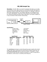
1.3 BASE STATION
Purpose: A base station utilizes a computer
to collect data from the field
station(s). Normally, all
communication to the field stations
originate at the base station. Data
retrieval, remote programming, and
system analysis can all be done
from the base station.
Equipment Required:
• Radio
• RF Base Station
• Computer with PC208W
software
• Antenna and antenna cable
• AC power
815 W. 1800 N. Logan Utah 84321-1784 (801) 753-2342 FAX (801) 750-9540
Copyright(c) 1996
Setup Instructions: Disk 1 of 4
1. Start Microsoft Windows
2. Insert Disk 1 in drive A.
3. From Program Manager, select File menu and
choose Run
4. Type a:\setup and press ENTER.
Datalogger Support Software for Windows
PC208W
To Antenna
RS232 Cable
CARRIER DETECT
RF232A
RF BASE STATION
POWER
ON
MADE IN U.S.A.
FIGURE 1-3. An RF Telemetry Base Station

SECTION 1. GENERAL RADIOTELEMETRY NETWORK
1-4
1.4 REPEATER
Purpose: To act as relay between two
communicating stations separated
by too long of a distance or an
obstacle which impedes direct
communication. A repeater is not
always required in a RF telemetry
network. A field station can also
function as a repeater.
Equipment Required:
• Radio
• RF Modem
• Antenna and antenna cable
• 12V and 5V power supply
(PS512M or CH512R and
BP12)
• Enclosure and other mounting
needs
PS512M
RF300
RF95A
FIGURE 1-4. A Typical RF Telemetry Repeater Station

2-1
SECTION 2. ASSEMBLING THE RADIOTELEMETRY NETWORK
This section provides a logical order for RF network assembly and deployment. Details of specific
components in the system are described in Section 3 “Radiotelemetry Network Components.” Section 3
is cross-referenced throughout this assembly section.
2.1 FINAL LAYOUT
The initial locations of the base, field, and
repeater stations have likely been determined
already. Locate RF stations on an area map,
preferably a topographic map. Draw a line
along every communication path. Each field
station must have a path connecting it back to
the base station. No path can be going through
a mountain or large obstacle; this would negate
the line-of-sight requirement. A station may
need to be moved or a repeater station may
need to be added if this requirement is not met.
At each station there is an RF modem. Each
modem requires a unique ID number (Station
ID). The number may range from 0 to 255. On
the map, label the base station as 254. Label
the remaining stations with different ID
numbers. Later, each modem will be set with
the corresponding ID number. The Station ID,
similar to a phone number, allows the base
station to call many different field stations.
2.2 INSTALL BASE STATION
2.2.1 BASE STATION HARDWARE
The major component of the base station is the
RF232A Base Station. Refer to Section 3.5 for
location drawings and a description of the
RF232A Base Station.
1. Remove the top of the RF232A by
unscrewing the four screws on the sides.
2. Remove the radio and its cable from its
mounting bracket. Mount the radio directly
onto the bottom of the RF232A. Secure the
BNC connector from the radio's cable to its
hole on the back of the RF232A. See
Figure 3-7 for assistance.
3. Connect the radio to 12 V, ground, and the
RF Modem (RF95A). The RF modem is
located behind the front panel above the
"POWER ON" light. See Figure 3-8 for
assistance.
CAUTION: Radio transmission without an
antenna connected can damage radio.
4. Mount the base station antenna in a
location that is higher than any surrounding
buildings or obstacles. Refer to Section 3.3
for more information on mounting the
antenna.
5. After the antenna is mounted, connect the
coax cable between the antenna and the
BNC connector mounted in Step 2.
6. Replace the cover of the RF232A.
7. Connect a large gauge (approximately 8
AWG) copper wire from the antenna to a
good earth ground. This is for lightning
protection. This is required for any
antenna, especially if the coax cable from
the antenna goes inside a building.
8. Connect a 25-pin RS232 cable from the
computer serial port to the RF232A.
9. After verifying that the RF232A power
switch is off, plug in the RF232A's wall
transformer.
2.2.2 PC208W DATALOGGER SUPPORT
SOFTWARE
Once the base station hardware is installed, the
PC208W software must be setup. If PC208W
is not installed on the computer, you will need to
install it. Refer to the PC208W Manual if you
have questions about the installation procedure
or PC208W.
There are eight main windows in PC208W:
• SETUP - Used to define communication
paths, set data collection parameters, and
schedule automatic data collection.
• CONNECT - Used for manual
communications with field site. Supports
real time data display, graphs, data retrieval
and program transfer.
• STATUS - Shows status of schedules and
communication information.
• PROGRAM - Editor to aid writing datalogger
programs.

SECTION 2. ASSEMBLING THE RADIOTELEMETRY NETWORK
2-2
• REPORT - Generates reports and reduces
data stored on computer.
• VIEW - Used to view text files.
• STG MODULE - Used to service storage
modules, SM192 or SM716.
• HELP - On line help. Also accessed
anywhere by typing F1.
PC208W uses a main tool bar to access each
of the eight windows. The shape of the main
tool bar can be changed using standard
Windows methods. Closing the main tool bar
closes all other PC208W windows.
The SETUP window is used to create a device
map which contains the RF Link information.
This information includes the station ID,
communication path and conditions for calling a
particular field station. Procedures for creating an
RF communications link are explained in section
1 of the PC208W manual.
Basic steps required to setup an RF link include:
1) select appropriate communications port (COM
Port), 2) attach RF modem to COM port, and 3)
attach datalogger to RF modem. The default COM
port settings should not be changed. The RF
modem default settings will work for current
hardware. Use the hardware tab to select 1200
baud for RF systems using the DC95. The default
datalogger settings do not need changing except for
the “Dialed using RF 95 path:”.
The RF Path (Dialed Using RF 95 Path:), found on
the datalogger hardware tab of the setup screen,
designates which field station to call. In the
example shown, the base station will call the field
station with an RF path of 10. If a repeater is
needed to contact Field Station 10, the repeater ID
must also be specified. For example, "RF Path: 5
10F," would call Field Station 10 through a repeater
with a Station ID of 5. The "F" at the end of the RF
Path is optional and is explained later. Click on
Save Edits.

SECTION 2. ASSEMBLING THE RADIOTELEMETRY NETWORK
2-3
Select the Appropriate Communications port. If your computer uses COM2, click the “Add COM port”
button to add an RS232 communications port. Next click the “Add Device” button.
When the “Add Device” button is clicked the “Add New Device” dialog box opens. Select the RF Modem
and attach to the appropriate RS232 communications port. Click OK.

SECTION 2. ASSEMBLING THE RADIOTELEMETRY NETWORK
2-4
This window shows the RF modem (RF1) attached to RS232 communication port 2. Next use the Add
Device button again to connect the datalogger to RF1.
This window shows the CR10X datalogger connected to the RF modem. Notice the Dialed Using RF95
path has been set to 10F. The RF95A path is unique to the RF95A dip switch settings.

SECTION 2. ASSEMBLING THE RADIOTELEMETRY NETWORK
2-5
2.3 INSTALL NEAREST REPEATER/
FIELD STATION
Now to install the nearest field station. If it
communicates with the base station via a
repeater, the repeater station must also be
installed.
Following is the order in which a general RF
field station should be installed. A repeater
station is installed in the same order. For
instructions on installing any particular
component, refer to either Section 3 of this
manual or the Weather Station Manual.
1. Tripod or tower
2. Enclosure and datalogger
3. Antenna - Orient correctly; remember
direction and polarization
4. Solar Panel
5. Power Supply
6. Sensors
7. RF Modem - Set the Station ID according to
the map
8. Radio - Make sure to connect to RF
Modem, to power supply, and turn on power
supply
2.4 TEST THE RADIOTELEMETRY LINK
With the field station installed, return to the
base station for initial testing of the
communication link. An RF link can also be
tested at the field site with a portable base
station; hardware requirements for the portable
base station are described in Appendix B.
Testing begins with turning the RF232A base
station on. A quick check of connections is in
order. Start PC208W software and open the
Connect Window. The “Station List” will show
all dataloggers or field stations available. Using
the mouse, highlight the datalogger of interest
then click on the Connect button. The software
requires about 15 seconds to establish a PC to
datalogger RF link. The computer is “talking”
with the datalogger when the first button to the
right of the Connect button changes from
Terminate to Disconnect.
If you do not click on the Disconnect or
Terminate button before closing the Connect
window, PC208W will automatically start calling
the datalogger when the Connect window is
reopened.
2.4.1 A SUCCESSFUL TEST
The test is considered successful if you
establish communications between the PC and
the datalogger.
2.4.2 AN UNSUCCESSFUL TEST
When an RF test is unsuccessful, there are
three ways to troubleshoot the system:
1. Verify everything is connected properly.
See Section 2.5.1 for more suggestions.
2. Use the error messages in the error file to
identify where the link is breaking down.
See Section 2.5.2 for more information.
3. Try communicating from the base station to
the field station, one step at a time. Identify
where communications failed. See Section
2.5.3 for more information.
2.5 TROUBLESHOOTING UNSUCCESS-
FUL COMMUNICATION ATTEMPTS
2.5.1 TROUBLESHOOTING PHYSICAL LINK
BETWEEN BASE AND FIELD STATION
When communication is not established,
troubleshooting begins with the simplest RF link
in the system, which is usually communication
with the nearest field station. There is NO
substitute for first checking the hardware
connections, Station IDs, and everything listed
in the previous section. Below are a few
additional items to check:
1. Antenna is used in proximity of metal.
2. Transmitting inside a building.
3. Damaged or shorted cables.
4. Bad or improper connections.
5. Antenna frequency does not match the
radio frequency.
6. Base and field station radios aren't using
same frequency.
7. Datalogger power drops below 9.6 Volts
during RF transmission. Use datalogger
Instruction 10 or volt meter to measure
battery voltage.
If the field station's RF95A Modem's Carrier
Detect light goes on, then at least a signal is
reaching the site. If this occurs, check the
following:

SECTION 2. ASSEMBLING THE RADIOTELEMETRY NETWORK
2-6
1. RF modem's ID matches ID in the RF Path.
2. Field station's radio and datalogger have
sufficient power.
3. Radio is connected to RF modem.
4. RF modem is the only thing connected to
datalogger's 9-pin connector.
2.5.2 ERROR MESSAGES
PC208W will log all activity related to each
Communications port (COM port). There are
two ways to view the messages. On the
PC208W main tool bar, click the Status button.
The lower right part of the Status window has a
button labeled “View Messages”. Click the View
Messages button. The message window lists
all events. The Status window has a check box
to allow these messages to be logged to disk.
The log file is a text file.
One possible error message is "RF1 Failed to
Get Attention." This message indicates
PC208W cannot communicate with the RF95A
modem. Check the following items:
1. RF232A Base Station plugged into
computer and wall outlet?
2. RF232A Power Switch turned on?
3. Has PC208W been set up correctly?
4. Is the proper COM port specified in the
Setup window?
5. Is the SC12 9-pin ribbon cable inside the
RF232A connected from the small circuit
board to the RF95A Modem?
6. Is there other software open that uses a
COM port?
Another possible error message is "CR10X_1
Failed to Connect" (where “CR10X_1” is the
station name). If this message is given without
the previous message, "RF1 Failed to Get
Attention", PC208W did connect with the RF
modem but not the datalogger. In this case,
check the following items:
1. Are the radios plugged in to the RF
modems?
2. Are the radios connected to power?
3. Verify that nothing but an RF modem is
connected to the datalogger's 9-pin
connector.
4. Are Station IDs set properly in the RF
Modems?
5. Is the RF Path in the Setup Window
correct?
6. Are the antennas oriented correctly?
7. Check all antenna cable connections.
8. Turn radio off. Unplug the SC12 9-pin
ribbon cable from the RF95A in the
RF232A, reconnect the SC12 cable and
watch the carrier detect light. Does the light
stay on for one second, off for one second,
on for one second, and then off? If not, the
RF95A could have bad RAM or ROM. Also
check the field/repeater station modems.
9. Is the field station datalogger turned on and
does it have sufficient power?
VERIFY NEXT ERROR MESSAGE
The error message "RF Modem Does Not
Respond" can occur if communication is not
returned to the base station. Check the
following items:
1. Are all RF Modems connected to radios and
dataloggers?
2. Are the antennas oriented properly?
3. Is the SDC switch open?
4. Is the proper COM port being specified?
2.5.3 TROUBLESHOOTING WITH THE
TERMINAL EMULATOR
A general understanding of the communication
sequences is necessary to properly trouble-
shoot an RF link. The base station RF modem
(RF95A) is called the Start Of Link modem, or
SOL modem. The field station RF modem is
called the End Of Link modem, or EOL modem.
When powered up, the SOL modem
immediately goes into a Wait Mode. The
RF95A Modem has five different modes of
operation; these are described in Section 3 of
this manual.
PC208W, Connect window has three tabs:
Tools, Numeric Display and Terminal Emulator.
With the Tools tab active, select the datalogger
of interest in the “Station List”. Select the
“Terminal Emulator” tab. Once in the Terminal
Emulator window, select “Open Port”. Terminal
Emulator allows you to send individual
commands to each device in the

SECTION 2. ASSEMBLING THE RADIOTELEMETRY NETWORK
2-7
communication path. This will allow you to test
each piece of the communication path
separately.
Try the following TASKs in order.
TASK A, Contact RF232A: Press [ENTER] a
few times, to set the baud rate between the
Base Station's RF modem and the computer.
This baud rate can be set at 300, 1200, or 9600
baud. The RF95A will detect the computer’s
baud rate and match it.
RESPONSE IF SUCCESSFUL: "!" prompt
given, SOL modem is now in the Local
Command Mode. This is where PC208W is
communicating with the RF232A base station.
If TASK A is unsuccessful, check:
1. Communication port (COM port) could be
configured improperly, computer setup.
2. The wrong COM port may be specified in
the Station File, PC208W setup.
3. Communication cable may be connected to
the wrong port. Use the correct serial port,
not the parallel port.
4. Computer mouse driver could be interfering
with COM port.
5. The base station or radio may not be
powered sufficiently.
6. The radio and RF modem may not be
connected properly.
7. Communications cable between computer
and RF232A must be standard RS232
cable.
TASK B: Task A must be successful before
Task B can be tested. To test the RF link; enter
the 'RF Path' at the “!” prompt. For example,
"S5 8F" communicates to a field station with a
Station ID of 8 through a repeater with an ID of
5. After typing the 'RF Path', press [ENTER].
RESPONSE IF SUCCESSFUL: "$" prompt
given. The dollar sign prompt is returned by the
EOL modem. The “$” indicates you are now
communicating with the modem at the field site.
Things to check if TASK B is unsuccessful:
1. Improper antenna orientation.
2. Bad connections on the antenna cables, or
improper antenna cables.
3. Insufficient current supply at the base
station. Is AC power good?
4. Field station radio is not connected to power
or power supply is weak. Check battery
voltage under load, should be no less than
11.7 volts. Battery voltage no load and no
charging source should be about 12.4 volts.
5. Field station radio and RF modem may not
be connected properly. Check cable.
6. Field station RF modem is not receiving 5
Volts from datalogger connection on pin 1
of the 9-pin cable. The RF modem must be
connected to the datalogger Serial I/O or
CS /IO port with a straight through cable,
SC12.
7. Using wrong RF path. Are the RF95A dip
switches set correctly?
TASK C: Establish link and baud rate between
RF Modem and Datalogger by slowly pressing
[ENTER] a few times. Pause about 2 seconds
between each press of the enter key.
RESPONSE IF SUCCESSFUL: "*" from
datalogger. The Asterisk prompt indicates the
datalogger is now communicating with the
computer at the base station.
Things to check if TASK C is unsuccessful:
1. Datalogger is on and has sufficient power.
2. Datalogger does not think it is still
communicating with some other device like
a CR10KD keypad or phone modem.
3. Datalogger and RF Modem are the only
devices connected together on the 9-pin
connections.
Upon successful completion of TASK C, the
datalogger is now in standard Telecom-
munications Mode. See Section 5 of the
datalogger manual for more information about
the Telecommunication mode. At this point the
SOL modem and EOL modem will be in the
Transparent Mode of operation. Type "A," wait
2 seconds, and then type [ENTER] to receive a
status sequence from the datalogger. If
everything is successful, type “E” to drop the
link. If task C is successful, PC208W should be
able to call the field site.

SECTION 2. ASSEMBLING THE RADIOTELEMETRY NETWORK
2-8
This is a blank page.

3-1
SECTION 3. RADIOTELEMETRY NETWORK COMPONENTS
3.1 RF95A MODEM
The RF95A is an interface between the
computer and the radio when used at a base
station, and an interface between the radio and
the datalogger at a field station. In a repeater
station, the RF95A is an interface between two
other communication stations.
The RF95A replaces Campbell Scientific's
RF95, DC95 and SDC RF Modems. The
RF95A is compatible with previous modems.
Refer to Appendix F “Equipment Compatibility"
for compatibility considerations. The RF95A is
the same RF modem as the RF95, except the
RF95A strobes power to the RF300 radio and
uses a different operating system. This is done
to reduce current consumption and extend
battery life. The RF95A should be used with the
RF300 radio.
3.1.1 PHYSICAL DESCRIPTION
The front panel of the RF95A is shown in Figure
3-1. There are two ports for interfacing external
devices. The port labeled TRANSCEIVER
connects to the radio, and the port labeled
SERIAL I/O connects to the datalogger,
PS512M or CH512R in the case of a repeater or
phone-to-RF base station. The red light labeled
CARRIER DETECT is used primarily to indicate
when a carrier frequency has been detected by
the radio. The RF95 to RF100/RF200 cable is
different than the RF95A to RF300 cable.
3.1.2 RF95A STATES
The RF95A Modem operates in one of two
separate states. The RF95A can be utilized in
either the RF95A-ME (Modem Enable) state or
the RF95A-SDC (Synchronous Device
Communication) state. The proper state must
be determined before employing the RF95A in
the field. A switch inside the RF95A needs to
be set accordingly.
The RF95A-ME state is ALWAYS used with
21X and CR7 dataloggers. The RF95A-ME
state is NORMALLY used with all dataloggers.
SDC compatible dataloggers (CR10, CR10X,
CR23X, CR510, and CR500) can also use the
RF95A-SDC state. The SDC state has the
advantage that a phone-to-RF base station can
have measurement capability. Only the RF95A
at a phone-to-RF base station with
measurement should to be switched to the
RF95A-SDC state.
A switch with nine different dip switches is
inside the RF95A; the RF95A cover must be
removed to locate the switch. The ninth switch
sets the RF95A state. The RF95A-ME state is
chosen by setting the ninth dip switch open,
represented by 1. The RF95A-SDC state is
chosen by setting the ninth dip switch closed,
represented by 0. Refer to Figure 3-2.
RF95A
FIGURE 3-1. The RF95A Modem

SECTION 3. RADIOTELEMETRY NETWORK COMPONENTS
3-2
TABLE 3-1. A Sample of Station ID Numbers
and the Corresponding Switch Settings
Station Switch Settings
ID 1234
56789
0 0000 0000X
10 0101 0000X
20 0010 1000X
30 0111 1000X
40 0001 0100X
50 0100 1100X
60 0011 1100X
70 0110 0010X
80 0000 1010X
90 0101 1010X
100 0010 0110X
110 0111 0110X
120 0001 1110X
130 0100 0001X
* Station ID 255 is reserved for
phone-to-RF base stations.
The RF95A is shipped with the switch set for
the RF95A-ME state and station ID of 1.
Further information on the RF95A compatibility
with older Campbell Scientific equipment can be
found in Appendix F “Equipment Compatibility.”
3.1.3 SETTING STATION ID
Each RF95A, including the one in the RF base
station, must have a unique Station ID. The
station ID is similar to a phone number. This
allows one base station to communicate with
any one particular field station.
The Station ID can be any number from 1 to
255. The Station ID is set with the switch inside
the RF95A. The first eight dip switches are
used to set the Station ID. Table 3-1 shows the
switch settings for several Station ID numbers.
Appendix A shows all possible Station ID
numbers. The dip switches can either be open,
represented by 1, or closed, represented by 0;
X in Table 3-1 refers to "don't care." The ninth
dip switch is set according to the desired RF95A
state, see Section 3.1.2 "RF95A States." All
RF95s are shipped with a Station ID of 1 and
are set in the RF95A-ME state. RF95s inside
the RF base station ship with a station ID of 254
and RF95A-ME state.
FIGURE 3-2. Setting the Station ID
3.1.4 THE CARRIER DETECT LIGHT
The Carrier Detect light on the front panel of the
RF95A has several purposes. The primary
function of the light is to indicate when data is
being received or transmitted. The light will stay
on when a network frequency originating from
another RF95A is detected. If a signal is
detected which isn't intended for that station, the
light will shut off after about two-tenths of a
second.
The Carrier Detect light can also be used to
check the RAM (Random Access Memory) and
ROM (Read Only Memory) of the RF95A. With
the radio disconnected and the datalogger in
the LOG (*0) Mode, connect the datalogger to
the RF95A Serial I/O Port with a 9-pin ribbon
cable. The sequence of the light flashing after
connection indicates the RAM and ROM status.
Both the RAM and ROM are good if the light
goes on for one second, off for one second, and
then back on for one second. The RAM is
faulty if the light is on for one half second and
off for one half second, continuously. The ROM
is faulty if the light goes on for one second, off
for one half second, on for one half second, and
then off for one half second, continuously.
3.1.5 DATA TRANSFER RATE
The data transfer rate is the time it takes to get
data from the datalogger to the computer. In
general, data can be transferred at a rate of
about 30 data points/second (60 bytes/second)
without a repeater. If a repeater is used, an
approximate data transfer rate is 22 data
points/second.
/