Talkswitch TALKSWITCH 48-CA User manual
- Category
- IP phones
- Type
- User manual
This manual is also suitable for

USER GUIDE
TALKSWITCH 48-CA/CVA
v3.21

COPYRIGHT INFORMATION
TalkSwitch. Copyright 2005. All Rights Reserved.
Reproduction, adaptation or translation without prior written permission is
prohibited, except as allowed under the copyright laws.
Information in this user guide is subject to change without notice and does not
represent any commitment on the part of TalkSwitch. No part of this user guide
may be reproduced or transmitted in any form or by any means, electronic or
mechanical, including photocopying, recording, or information storage and
retrieval systems, or translated to another language, for any purpose other than
the licensee’s personal use and, as specifically allowed in the licensing
agreement, without the express written permission of TalkSwitch.
Third Edition, August 2005.
CT.TS005.016.EN
TalkSwitch is a division of Centrepoint Technologies Inc.

TABLE OF CONTENTS
CHAPTER 1 Introduction to VoIP
How does VoIP work? . . . . . . . . . . . . . . . . . . . . . . . . . . . . . . . . . . . . . . . . . . . . . . . . . . . . . . . . . . . 1
Does a VoIP call sound like a regular phone call?. . . . . . . . . . . . . . . . . . . . . . . . . . . . . . . . . . . . . 1
If the power goes out, does the VoIP network stay up?. . . . . . . . . . . . . . . . . . . . . . . . . . . . . . . . . 2
What happens to VoIP if the IP network fails?. . . . . . . . . . . . . . . . . . . . . . . . . . . . . . . . . . . . . . . . 2
I have a firewall and heard that it can prevent VoIP calls from passing through. Is this true? . . 2
What is SIP? . . . . . . . . . . . . . . . . . . . . . . . . . . . . . . . . . . . . . . . . . . . . . . . . . . . . . . . . . . . . . . . . . . 2
What is a VPN? Can a VPN help me to carry data securely over the Internet? . . . . . . . . . . . . . . . 3
What’s the difference between a Public IP Address and a Private IP Address? . . . . . . . . . . . . . . 3
What is NAT and how does it affect VoIP? . . . . . . . . . . . . . . . . . . . . . . . . . . . . . . . . . . . . . . . . . . . 4
What’s the difference between a Static IP Address and a Dynamic IP Address? . . . . . . . . . . . . 3
What effect does this have on VoIP? . . . . . . . . . . . . . . . . . . . . . . . . . . . . . . . . . . . . . . . . . . . . . . . 4
What is a SIP Proxy and Registrar?. . . . . . . . . . . . . . . . . . . . . . . . . . . . . . . . . . . . . . . . . . . . . . . . . 4
What is Dynamic DNS? . . . . . . . . . . . . . . . . . . . . . . . . . . . . . . . . . . . . . . . . . . . . . . . . . . . . . . . . . . 5
What is the drawback of using Dynamic DNS? . . . . . . . . . . . . . . . . . . . . . . . . . . . . . . . . . . . . . . . 5
How often will my Public IP address change? . . . . . . . . . . . . . . . . . . . . . . . . . . . . . . . . . . . . . . . . 5
What is a port number? . . . . . . . . . . . . . . . . . . . . . . . . . . . . . . . . . . . . . . . . . . . . . . . . . . . . . . . . . 6
CHAPTER 2 Installing TalkSwitch
2.1 What’s included with TalkSwitch . . . . . . . . . . . . . . . . . . . . . . . . . . . . . . . . . . . . . . . . . . . . . 7
2.2 Front Panel Descriptions. . . . . . . . . . . . . . . . . . . . . . . . . . . . . . . . . . . . . . . . . . . . . . . . . . . . 8
2.3 Back Panel Descriptions — TalkSwitch 48-CA/CVA . . . . . . . . . . . . . . . . . . . . . . . . . . . . . . 9
2.4 Plugging into the Back Panel . . . . . . . . . . . . . . . . . . . . . . . . . . . . . . . . . . . . . . . . . . . . . . . 11
2.5 Attaching telephone lines to TalkSwitch line jacks . . . . . . . . . . . . . . . . . . . . . . . . . . . . . . 11
2.5.1 Attaching phones and other devices to TalkSwitch extension jacks . . . . . . . . . 11
2.5.2 Connecting devices to the Music and PA jacks . . . . . . . . . . . . . . . . . . . . . . . . . . 12
2.5.3 Connecting TalkSwitch to a LAN and/or PC . . . . . . . . . . . . . . . . . . . . . . . . . . . . . 12
2.5.3.1 Connecting TalkSwitch to a LAN for local configuration . . . . . . . . . . 13
2.5.3.2 Connecting TalkSwitch to a PC using a USB cable . . . . . . . . . . . . . . . 13
2.5.3.3 Connecting TalkSwitch to a PC using a Serial cable . . . . . . . . . . . . . 13
2.5.3.4 Connecting to TalkSwitch over IP . . . . . . . . . . . . . . . . . . . . . . . . . . . . 14

2.6 Using 2 or more TalkSwitch units on a LAN . . . . . . . . . . . . . . . . . . . . . . . . . . . . . . . . . . . . 14
2.6.1 Connecting 2 or more TalkSwitch units to a LAN . . . . . . . . . . . . . . . . . . . . . . . . . 14
2.6.2 Setting the Unit ID for the first time . . . . . . . . . . . . . . . . . . . . . . . . . . . . . . . . . . . 15
2.6.3 Changing the Unit ID . . . . . . . . . . . . . . . . . . . . . . . . . . . . . . . . . . . . . . . . . . . . . . . 16
2.6.4 Unit IDs and how they affect system extension numbers . . . . . . . . . . . . . . . . . . 16
2.6.5 Keeping track of the lines and extensions . . . . . . . . . . . . . . . . . . . . . . . . . . . . . . 17
2.6.6 Optimizing the system for networked use . . . . . . . . . . . . . . . . . . . . . . . . . . . . . . 17
2.7 Optimizing Your IP Network for VoIP . . . . . . . . . . . . . . . . . . . . . . . . . . . . . . . . . . . . . . . . . 18
2.7.1 The Broadband Connection . . . . . . . . . . . . . . . . . . . . . . . . . . . . . . . . . . . . . . . . . 18
2.7.2 The Router/NAT/Firewall . . . . . . . . . . . . . . . . . . . . . . . . . . . . . . . . . . . . . . . . . . . . 19
2.7.3 The Local Area Network . . . . . . . . . . . . . . . . . . . . . . . . . . . . . . . . . . . . . . . . . . . . . 20
CHAPTER 3 Configuring TalkSwitch
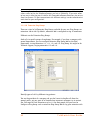
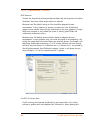
3.1 Installing the TalkSwitch Configuration Software . . . . . . . . . . . . . . . . . . . . . . . . . . . . . . . 21
3.2 Running the TalkSwitch software . . . . . . . . . . . . . . . . . . . . . . . . . . . . . . . . . . . . . . . . . . . . 22
3.3 Configuration . . . . . . . . . . . . . . . . . . . . . . . . . . . . . . . . . . . . . . . . . . . . . . . . . . . . . . . . . . . 23
3.3.1 System Information . . . . . . . . . . . . . . . . . . . . . . . . . . . . . . . . . . . . . . . . . . . . . . . . 27
3.3.1.1 Administration . . . . . . . . . . . . . . . . . . . . . . . . . . . . . . . . . . . . . . . . . . . 27
3.3.1.2 IP Configuration . . . . . . . . . . . . . . . . . . . . . . . . . . . . . . . . . . . . . . . . . . 28
3.3.1.3 VoIP Configuration . . . . . . . . . . . . . . . . . . . . . . . . . . . . . . . . . . . . . . . . 30
3.3.1.4 Telephone Lines . . . . . . . . . . . . . . . . . . . . . . . . . . . . . . . . . . . . . . . . . 32
3.3.1.5 VoIP Lines . . . . . . . . . . . . . . . . . . . . . . . . . . . . . . . . . . . . . . . . . . . . . . 34
3.3.1.6 Line Hunt Groups . . . . . . . . . . . . . . . . . . . . . . . . . . . . . . . . . . . . . . . . . 36
3.3.1.7 Fax Information . . . . . . . . . . . . . . . . . . . . . . . . . . . . . . . . . . . . . . . . . . 37
3.3.1.8 Local Extensions . . . . . . . . . . . . . . . . . . . . . . . . . . . . . . . . . . . . . . . . . 38
3.3.1.9 Remote Extensions . . . . . . . . . . . . . . . . . . . . . . . . . . . . . . . . . . . . . . . 40
3.3.1.10 Extension Ring Groups . . . . . . . . . . . . . . . . . . . . . . . . . . . . . . . . . . . . 42
3.3.1.11 On-hold/Ringback . . . . . . . . . . . . . . . . . . . . . . . . . . . . . . . . . . . . . . . . 43
3.3.2 Voicemail . . . . . . . . . . . . . . . . . . . . . . . . . . . . . . . . . . . . . . . . . . . . . . . . . . . . . . . . 45
3.3.2.1 Local Extension Voicemail . . . . . . . . . . . . . . . . . . . . . . . . . . . . . . . . . . 45
3.3.2.2 Remote Extension Voicemail . . . . . . . . . . . . . . . . . . . . . . . . . . . . . . . . 48
3.3.2.3 General Voicemail . . . . . . . . . . . . . . . . . . . . . . . . . . . . . . . . . . . . . . . . 51
3.3.2.4 Global Settings . . . . . . . . . . . . . . . . . . . . . . . . . . . . . . . . . . . . . . . . . . 54

3.3.3 Call Handling . . . . . . . . . . . . . . . . . . . . . . . . . . . . . . . . . . . . . . . . . . . . . . . . . . . . . 56
3.3.3.1 Modes . . . . . . . . . . . . . . . . . . . . . . . . . . . . . . . . . . . . . . . . . . . . . . . . . 56
3.3.3.2 Auto Attendant . . . . . . . . . . . . . . . . . . . . . . . . . . . . . . . . . . . . . . . . . . 57
3.3.3.3 Telephone Lines . . . . . . . . . . . . . . . . . . . . . . . . . . . . . . . . . . . . . . . . . 64
3.3.3.4 VoIP Lines . . . . . . . . . . . . . . . . . . . . . . . . . . . . . . . . . . . . . . . . . . . . . . 65
3.3.3.5 Local Extensions — Call Cascade . . . . . . . . . . . . . . . . . . . . . . . . . . . . 67
3.3.3.6 Remote Extensions — Call Cascade . . . . . . . . . . . . . . . . . . . . . . . . . . 69
3.3.3.7 Extension Ring Groups — Call Cascade . . . . . . . . . . . . . . . . . . . . . . . 71
3.3.4 Call Back/Call Bridge . . . . . . . . . . . . . . . . . . . . . . . . . . . . . . . . . . . . . . . . . . . . . . 73
3.3.4.1 Auto Call Back . . . . . . . . . . . . . . . . . . . . . . . . . . . . . . . . . . . . . . . . . . . 74
3.3.4.2 Prompted Call Back . . . . . . . . . . . . . . . . . . . . . . . . . . . . . . . . . . . . . . . 77
3.3.4.3 Call Bridge . . . . . . . . . . . . . . . . . . . . . . . . . . . . . . . . . . . . . . . . . . . . . 79
3.3.5 Options . . . . . . . . . . . . . . . . . . . . . . . . . . . . . . . . . . . . . . . . . . . . . . . . . . . . . . . . . 80
3.3.5.1 Audio Controls . . . . . . . . . . . . . . . . . . . . . . . . . . . . . . . . . . . . . . . . . . . 80
3.3.5.2 Transfer Options . . . . . . . . . . . . . . . . . . . . . . . . . . . . . . . . . . . . . . . . . 81
3.3.5.3 Miscellaneous . . . . . . . . . . . . . . . . . . . . . . . . . . . . . . . . . . . . . . . . . . . 83
3.3.5.4 Troubleshooting . . . . . . . . . . . . . . . . . . . . . . . . . . . . . . . . . . . . . . . . . 86
3.3.5.5 Troubleshooting — Advanced . . . . . . . . . . . . . . . . . . . . . . . . . . . . . . . 88
CHAPTER 4 Using TalkSwitch
4.1 In the Office — Receiving Calls with or without the Auto Attendant . . . . . . . . . . . . . . . . 91
4.1.1 Receiving calls using the Auto Attendant . . . . . . . . . . . . . . . . . . . . . . . . . . . . . . 91
4.1.2 Receiving calls without the Auto Attendant . . . . . . . . . . . . . . . . . . . . . . . . . . . . . 91
4.2 In the Office — Making and Receiving Calls. . . . . . . . . . . . . . . . . . . . . . . . . . . . . . . . . . . . 92
4.2.1 Making calls from a Local Extension . . . . . . . . . . . . . . . . . . . . . . . . . . . . . . . . . . 92
4.2.2 Receiving calls at a Local Extension . . . . . . . . . . . . . . . . . . . . . . . . . . . . . . . . . . . 92
4.2.3 Placing calls on Hold at a Local Extension . . . . . . . . . . . . . . . . . . . . . . . . . . . . . . 93
4.2.4 Transferring calls . . . . . . . . . . . . . . . . . . . . . . . . . . . . . . . . . . . . . . . . . . . . . . . . . 93
4.2.5 Call Park — Parking and retrieving callers . . . . . . . . . . . . . . . . . . . . . . . . . . . . . . 94
4.2.5.1 Parking a caller . . . . . . . . . . . . . . . . . . . . . . . . . . . . . . . . . . . . . . . . . . 94
4.2.5.2 Parking a caller using Auto Park . . . . . . . . . . . . . . . . . . . . . . . . . . . . . 94
4.2.5.3 Retrieving a parked call . . . . . . . . . . . . . . . . . . . . . . . . . . . . . . . . . . . 95
4.2.5.4 Using Call Park with the External Paging option . . . . . . . . . . . . . . . . 95
4.2.6 Call Queue/UCD/Call Waiting — Queuing and retrieving callers . . . . . . . . . . . . 95
4.2.6.1 Queuing calls to a single extension . . . . . . . . . . . . . . . . . . . . . . . . . . 95
4.2.6.2 Queuing callers to an Extension Ring Group. . . . . . . . . . . . . . . . . . . . 96

4.2.7 Using the TalkSwitch Call Waiting feature . . . . . . . . . . . . . . . . . . . . . . . . . . . . . . 96
4.2.8 Conference calling with TalkSwitch . . . . . . . . . . . . . . . . . . . . . . . . . . . . . . . . . . . 97
4.2.9 Making and receiving calls using VoIP . . . . . . . . . . . . . . . . . . . . . . . . . . . . . . . . . 98
4.2.10 Using Phones connected in parallel to TalkSwitch . . . . . . . . . . . . . . . . . . . . . . . 98
4.2.11 Modems and telephone line access . . . . . . . . . . . . . . . . . . . . . . . . . . . . . . . . . . . 99
4.3 Out of the Office — Receiving Calls through Call Forwarding . . . . . . . . . . . . . . . . . . . . . 100
4.3.1 The three ways to forward calls . . . . . . . . . . . . . . . . . . . . . . . . . . . . . . . . . . . . . 100
4.3.2 Transferring calls from a Remote Extension . . . . . . . . . . . . . . . . . . . . . . . . . . . 101
4.3.3 Screening options for forwarded calls . . . . . . . . . . . . . . . . . . . . . . . . . . . . . . . . 101
4.3.4 Calls over VoIP with SIP phones and Gateways . . . . . . . . . . . . . . . . . . . . . . . . 102
4.4 Using the TalkSwitch Voicemail System . . . . . . . . . . . . . . . . . . . . . . . . . . . . . . . . . . . . . 103
4.4.1 Activating Voice mailboxes . . . . . . . . . . . . . . . . . . . . . . . . . . . . . . . . . . . . . . . . . 103
4.4.2 Retrieving Messages/Accessing a Voicemail box . . . . . . . . . . . . . . . . . . . . . . . 104
4.4.3 Pager and Cell Phone notification . . . . . . . . . . . . . . . . . . . . . . . . . . . . . . . . . . . 106
4.5 Music-on-Hold . . . . . . . . . . . . . . . . . . . . . . . . . . . . . . . . . . . . . . . . . . . . . . . . . . . . . . . . . . 106
4.6 Mode Switching Options . . . . . . . . . . . . . . . . . . . . . . . . . . . . . . . . . . . . . . . . . . . . . . . . . 107
4.7 Out of the Office — Making Calls with Call Back and Call Bridge . . . . . . . . . . . . . . . . . . 108
4.7.1 Using Call Bridge . . . . . . . . . . . . . . . . . . . . . . . . . . . . . . . . . . . . . . . . . . . . . . . . . 108
4.7.2 Using Call Back . . . . . . . . . . . . . . . . . . . . . . . . . . . . . . . . . . . . . . . . . . . . . . . . . . 109
4.8 Upgrading the TalkSwitch Software and Firmware . . . . . . . . . . . . . . . . . . . . . . . . . . . . . 110
APPENDICES
Appendix A — Help and Troubleshooting . . . . . . . . . . . . . . . . . . . . . . . . . . . . . . . . . . . . . . . . . 113
Appendix B — Using TalkSwitch with Telephone Company Calling Services . . . . . . . . . . . . . 121
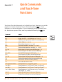
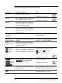
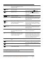
Appendix C — Quick Commands and Touch-Tone Functions . . . . . . . . . . . . . . . . . . . . . . . . . . 125
Appendix D — Safety Precautions and Regulatory Information . . . . . . . . . . . . . . . . . . . . . . . . 129
Appendix E — One Year Warranty . . . . . . . . . . . . . . . . . . . . . . . . . . . . . . . . . . . . . . . . . . . . . . . 133
Appendix F — Return Policy . . . . . . . . . . . . . . . . . . . . . . . . . . . . . . . . . . . . . . . . . . . . . . . . . . . . 137
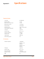
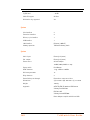
Appendix G — Specifications. . . . . . . . . . . . . . . . . . . . . . . . . . . . . . . . . . . . . . . . . . . . . . . . . . . 139
Appendix H — TalkSwitch and Power Interruptions . . . . . . . . . . . . . . . . . . . . . . . . . . . . . . . . . 141
GLOSSARY. . . . . . . . . . . . . . . . . . . . . . . . . . . . . . . . . . . . . . . . . . . . . . . . . . . . . . . . . . . . . . . . 143

Introduction to VoIP 1
This section applies only to customers using the TalkSwitch 48-CVA. Please proceed to
Section 2 if you have a TalkSwitch 48-CA (non VoIP version).
The TalkSwitch 48-CVA is a hybrid PSTN/VoIP phone system. The addition of VoIP to
the TalkSwitch product line adds the ability to use a broadband IP connection for voice
calls.
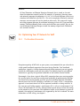
The TalkSwitch 48-CVA can be used in many different applications. The most popular
configurations are multi-branch, teleworker integration and service provider
integration.
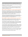
How does VoIP work?
Voice over IP, or VoIP, sends calls over the Internet or any Internet Protocol (IP)
network by converting voice traffic into data packets. These packets are then routed
over the IP network in the same way as other data, reassembled at the point of arrival,
and then converted back to voice.
Does a VoIP call sound like a regular phone call?
Under the right conditions, VoIP calls can sound as good or even better than regular
phone calls. Voice quality is affected by numerous issues, including how it is
compressed for delivery over the Internet, decompressed, and how packets are
processed. A few steps can help ensure call quality.
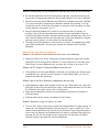
1. High-speed connections on both ends of the call: Good quality VoIP is not possible
over a dial-up modem connection. To support more simultaneous VoIP calls, a
broadband connection is required. Please visit our site at www.talkswitch.com/
voip/voip_test.php to determine what your Internet connection can support.
2. Choose the right CODEC for your location: TalkSwitch supports 3 CODECs
(compression algorithms). The default CODEC is G.729 which uses approximately
25Kbps bandwidth upstream and 25Kbps bandwidth downstream for each call.
G.729 provides very good call quality while minimizing bandwidth usage.
The G.726 (32Kbps) CODEC is a better quality solution compared to the G.729 CODEC. It
does, however, require more bandwidth per call. A G.726 call will typically require
50Kbps bandwidth upstream and 50Kbps bandwidth downstream for each call.
CHAPTER 1 Introduction
to VoIP

2 TalkSwitch User Guide
The G.711 CODEC provides the best voice quality. The trade-off is the bandwidth
requirement. G.711 calls typically requires up to 100Kbps bandwidth upstream and
100Kbps bandwidth downstream.
For example, if you have a typical 1Mbps ADSL connection from your service provider,
this usually means that you have an upstream bandwidth of approximately 380 Kbps.
Just because the service provider says that you have 380 Kbps upstream bandwidth
does not mean that the full 380 Kbps is available. In fact, a conservative approach is to
estimate just over half of the upstream bandwidth as being available. In this case you
could safely support 2 simultaneous G.711 calls or 4 simultaneous G.726 calls or 10
simultaneous G.729 calls. These estimates do not factor in other data traffic on the
network at the same time. With additional traffic on the Internet or private IP
network, the number of simultaneous calls supported by the link is reduced.
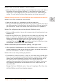
If the power goes out, does the VoIP network stay up?
To ensure a reliable network connection, all elements of the VoIP network should be
connected to back-up power supplies (UPS). These elements might include LAN
switches, routers, firewalls, broadband connection devices (ie. cable modems, DSL
modems), and VoIP devices. If the power goes out at the Internet Service Provider,
then no VoIP calls can be made. Calls can still be placed over the regular phone lines.
What happens to VoIP if the IP network fails?
If the connection to the IP network is lost, it will not be possible to make VoIP calls.
Calls can still be placed over the regular phone lines.
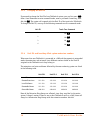
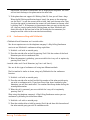
I have a firewall and heard that it can prevent VoIP calls from passing
through. Is this true?
The purpose of a firewall is to control what kinds of traffic enter and leave your
network. The TalkSwitch 48-CVA is designed with embedded applications to help
traverse firewalls properly. To allow VoIP calls to pass through your firewall, you may
need to use the port forwarding feature on your firewall.
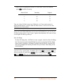
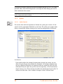
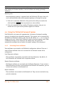
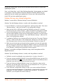
TalkSwitch 48-CVA by default uses the following ports for VoIP:
What is SIP?
The Session Initiation Protocol (SIP) is a signalling protocol used for establishing
sessions in an IP network. A session could be a simple two-way telephone call or it
could be a collaborative multi-media conference session.
Format Type Unit 1 Unit 2 Unit 3 Unit 4
RTP (voice): UDP 6000 - 6006 6010-6016 6020-6026 6030-6036
SIP (signaling): UDP 5060 (This port is mapped to only one unit)

Introduction to VoIP 3
Over the last couple of years, the Voice over IP community has adopted SIP as its
protocol of choice for signalling. SIP is an RFC standard (RFC 3261) from the Internet
Engineering Task Force (IETF), the body responsible for administering and developing
the mechanisms that comprise the Internet.
The IETF’s philosophy is one of simplicity: specify only what you need to specify. SIP is
very much of this mould; it just initiates, terminates and modifies sessions. This
simplicity means that SIP scales, it is extensible, and it sits comfortably in different
architectures and deployment scenarios.
What is a VPN? Can a VPN help me to carry data securely over the Internet?
VPN stands for Virtual Private Network. It is a means of having the advantages of a
private network on a shared public infrastructure like the Internet. A VPN provides
security by using encryption/decryption. Using a process called ‘tunneling’, private
data is encrypted and then encapsulated before being sent across the network. These
packets of information are sent to their destination. Only those with the correct
protocol information are able to enter a company’s network.
A VPN is very useful for providing employees with remote access to the company
network without compromising security. Encryption can have a negative impact on the
call quality, as the overhead on the network connection is increased. For example,
IPSec adds approximately 10 per cent overhead to VPN traffic.
What’s the difference between a Public IP Address and a Private IP Address?
A Public IP Address is a globally unique number that identifies a device on the
Internet. If you want someone on the Internet to connect to you, then you must tell
them your public address. Also known as your “real” or “external” address.
Private IP Addresses are typically assigned to devices on a LAN (Local Area Network)
and are not routable outside the LAN. Private IP Addresses are usually in the range
192.168.x.x, 172.16.x.x or 10.x.x.x. These IP addresses are typically used where you
have multiple computers all sharing the same Internet connection.
To access the Internet, a computer or VoIP device must have an IP address. So what do
you do if your ISP (Internet Service Provider) has provided you with only 1 IP address
but you have more than 1 device that requires Internet access? The solution is to give
each of the devices on the LAN a Private IP Address. A router makes them work by
performing Network Address Translation (NAT - See the next topic for details).
Note that addresses of the form192.168.x.x, 172.16.x.x or 10.x.x.x are not recognized
on the Internet and can only be used for private networks. For example, if you tell
someone on the Internet to connect to you using a 192.168.x.x address, it will not
work. Instead, you must provide your real/Public IP Address.

4 TalkSwitch User Guide
What is NAT and how does it affect VoIP?
Network Address Translation (NAT) allows multiple devices to share the same external
IP address to access resources on the Internet. NAT is typically used to allow all the
devices in a subscriber’s local area network to access the Internet through a router
with a single public IP address assigned by the Internet Service Provider.
If a VoIP device is sitting behind a NAT, the private IP address assigned to it is not
usable for communications with the entities outside the private network. The VoIP
device must substitute the private IP address information with the proper external IP
address/port in the mapping chosen by the underlying NAT to communicate with a
particular public peer address/port. TalkSwitch can automatically check for the
current public IP address and substitute the private IP address with the public address
so that VoIP traffic is properly routed through the NAT.
What’s the difference between a Static IP Address and a Dynamic IP
Address? What effect does this have on VoIP?
A Static IP Address is an address that is permanently assigned to a device. Typically, a
Static IP Address has to be assigned by the network administrator or Internet Service
Provider (ISP).
A Dynamic IP Address is an address that is temporarily assigned to devices by a DHCP
or PPP server that maintains and assigns a pool of IP addresses.
When deploying VoIP devices, it’s best to have a Static Public IP Address as this
prevents destinations from becoming unreachable for periods of time when the IP
address changes. But since this can be an expensive option, TalkSwitch 48-CVA
supports the ability to handle Dynamic Public IP addresses for the Internet
connection. TalkSwitch can automatically check for the current public IP address and
substitute the private IP address with the public address so that VoIP traffic is properly
routed through the NAT.
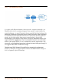
What is a SIP Proxy and Registrar?
SIP’s basic architecture is client/server in nature. The main entities in the SIP server
are the Proxy, Redirect Server and the Registrar.
TalkSwitch 48-CVA has the SIP Server fully integrated for easy deployment and
maintenance of your VoIP network. If you are deploying a multi-site configuration
which can comprise of TalkSwitch 48-CVA units, certified 3rd party gateways and
certified 3rd party SIP phones, then one TalkSwitch 48-CVA can act as the SIP Proxy
and Registrar. The other SIP end-points will register with this TalkSwitch 48-CVA and
all calls will be negotiated through this TalkSwitch 48-CVA.
When you first set up your VoIP device (TalkSwitch 48-CVA, gateway or phone), it will
register itself with the TalkSwitch 48-CVA that is configured as the SIP Server so that
calls can be directed to your location.

Introduction to VoIP 5
When you initiate a VoIP call, your device (TalkSwitch 48-CVA, gateway or phone) will
contact the TalkSwitch 48-CVA that is configured as the SIP Server to obtain the
contact information for the destination you are trying to reach. Once the information
is received, the call is established directly between your location and the destination.
The SIP Server is no longer involved in the call.
If the location of the SIP Proxy and Registrar has a Dynamic IP Address, then you will
have to use Dynamic DNS since the SIP Server location will be unreachable as soon as
the IP address changes.
What is Dynamic DNS?
Dynamic DNS is a Domain Name Service that is used with Dynamic IP addresses. DNS is
used to allow devices to find other devices on the Internet by name rather than by IP
address. Dynamic DNS allows you to use a domain name - FQDN (which does not
change) to locate a device with a Dynamic IP address.
There are companies on the Internet which can provide you with a DNS Address, even
if your IP address changes. For example www.dyndns.org or hn.org or www.no-ip.com.
You should consult with them about how to use their service. But the basic idea is that
you will receive an address something like myname.homeip.net which points to your IP
address (something like 209.210.230.140). This is important for locations where the
SIP Server resides and where the public IP address is dynamic. All other locations will
point to this SIP Server’s domain instead of an IP address.
What is the drawback of using Dynamic DNS?
When DNS records are updated, they have to be sent all over the world so that
everyone will be aware of the changes. Basically, one DNS server connects to another
and swaps information. In many cases, the DNS servers are updated very quickly.
Updates should take no longer than 15 minutes to propagate throughout the DNS
system. It is possible that propagation could take longer under extenuating
circumstances, but propagation shouldn’t take much more than an hour at the very
most.
How often will my Public IP address change?
This depends on the policies of your Internet Service Provider (ISP, the company that
provides your Internet access). It can be a matter of days, weeks or even months
before your IP address changes. A power loss or reboot to your cable or DSL modem
usually results in the assignment of a new IP address.
TalkSwitch has technology that helps keep this information up to date so that the
system can function properly after an IP address change has been detected and
updated.

6 TalkSwitch User Guide
What is a port number?
In an IP address like 64.26.209.103:5060, the port number is the number after the
colon ‘:’. For this example, 5060 is the specified port.
Port numbers are required so that a computer or device can support multiple
applications or streams of simultaneous data communication. Each stream or
application uses a unique port number. You can think of it like mailing a letter to
friend in an apartment building at a specific address. You need to specify the
apartment number as well as the building address, so that the mail can reach the
proper final destination.

Installing TalkSwitch 7
2.1 What’s included with TalkSwitch
The TalkSwitch 48-CA/CVA comes shipped with the following items:
1. The TalkSwitch Unit
2. AC Power Adapter (Warning: never use any power adapter other than the one
provided.)
3. 6' RJ-45 Ethernet Cable
4. 6' RJ-11 Telephone Cable – (4)
5. CD containing configuration software and documentation
6. Quick Reference Cards
7. TalkSwitch Start Guide
8. TalkSwitch Memory Card (optional)
If any of these items are missing, please contact your TalkSwitch dealer.
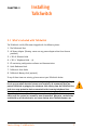
The TalkSwitch line jacks are sensitive to high-voltage spikes from lightning. If you
live in an area where electrical storms occur regularly, we recommend that you
protect TalkSwitch by plugging the telephone cords coming from the TalkSwitch line
jacks to a surge protection device connected to the incoming telephone lines.
If you live in an area with cold temperatures, do not plug TalkSwitch into a power
outlet until the system has warmed to room temperature. Otherwise, condensation
could build up on the electronics and cause damage when TalkSwitch powers up.
CHAPTER 2 Installing
TalkSwitch

8 TalkSwitch User Guide
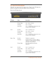
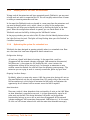
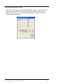
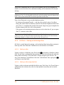
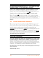
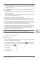
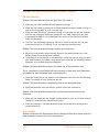
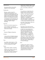
2.2 Front Panel Descriptions
TalkSwitch’s front panel consists of a power button (“Power”) and 5 LED lights that
indicate the usage of the lines with different states of illumination.
What do the LED lights tell you?
LED light: State Description
Line 1 On Solid Line 1 is currently in use.
Pulsing Slowly Line 1 caller is on hold.
Flickering Line 1 is ringing.
Quick Pulse Line 1 is engaged by a device that is shar-
ing the line with TalkSwitch.
Line 2 On Solid Line 2 is currently in use.
Pulsing Slowly Line 2 caller is on hold.
Flickering Line 2 is ringing.
Quick Pulse Line 2 is engaged by a device that is shar-
ing the line with TalkSwitch.
Power / Data On Solid TalkSwitch is powered on.
Flickering The PC connected (via Serial or USB) to
TalkSwitch is either sending or retrieving
information from TalkSwitch.
Pulsing Slowly Global Message Waiting Indicator
(optional).
Line 3 On Solid Line 3 is currently in use.
Pulsing Slowly Line 3 caller is on hold.
Flickering Line 3 is ringing.
Quick Pulse Line 3 is engaged by a device that is shar-
ing the line with TalkSwitch.

Installing TalkSwitch 9
For more details on line LED error codes, see Troubleshooting — Appendix A.
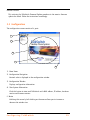
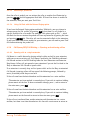
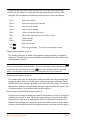
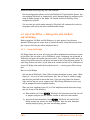
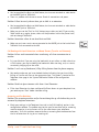
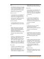
2.3 Back Panel Descriptions — TalkSwitch 48-CA/CVA
Before connecting all your phones and lines to TalkSwitch, you may want to proceed
with configuring the unit first. (See section 3.1) This will minimize the disruption
time for your telephone lines while setting up the system.
Line 4 On Solid Line 4 is currently in use.
Pulsing Slowly Line 4 caller is on hold.
Flickering Line 4 is ringing.
Quick Pulse Line 4 is engaged by a device that is shar-
ing the line with TalkSwitch.
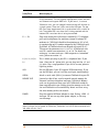
Jacks/Ports What to plug in
MUSIC Plug in a radio, CD player, PC soundcard or any other device that
emits an audio signal if you wish to use the TalkSwitch Music-on-
Hold feature. This is a 1/8" (3.5 mm) phono jack. Mono cables are
recommended. If you have multiple TalkSwitch units on a LAN,
you will need to provide a music source to each TalkSwitch.
PA Connect to a P.A. system if you wish to use the external paging
feature. This is a 1/8" (3.5 mm) phono jack. Mono cables are rec-
ommended. If you have multiple TalkSwitch units on a LAN, you
will need to provide a connection from each TalkSwitch to the PA
Amplifier.
LED light: State Description

10 TalkSwitch User Guide
The ‘PF’ box in between E4 and L1/L2 represents power failure support. In the event of a
power failure or loss of power to TalkSwitch, Extension 114 will be able to receive calls
and make calls on Line 1.
LAN PORT You can connect to an Ethernet hub using a Category 5 cable with
RJ-45 connectors. This will support configuration across the LAN
and Internet and support VoIP calls. If you have 2, 3 or more
TalkSwitch units, you can ‘network’ them and they will function as
a single system. There are 3 LEDs next to the LAN port. The top
LED is on when the ethernet link is synchronized with a switch or
hub. The middle LED is on when data is being received and the
bottom LED is on when data is being transmitted.
E1 — E8 Plug in any analog device that uses a standard (RJ-11) telephone
jack, such as telephones, fax machines, internal or external PC
modems, etc. TalkSwitch identifies the extensions as 1x1 to 1x8.
(x represents the unit ID number assigned to that TalkSwitch unit).
By default, all TalkSwitch units are shipped with a unit ID of 1.
This means the extensions are 111 to 118. A TalkSwitch with
unit ID 2 would have extensions 121 to 128. For details on
setting up 2 or more units on a LAN to operate as ‘networked’
units, please see section 2.5.
L1/L2, L2, L3/L4,
L4
This is where you plug in your RJ-11 telephone lines. If you
have 2 lines out of 1 phone jack, you can plug into the 1/2 and
3/4 jacks. Use a surge protector if you live in an area prone to
lightning strikes.
USB Use the USB port if your PC supports USB connectivity. If you
use the USB port, you can’t use the serial port simultaneously.
SERIAL Attach a serial cable (RS232) to connect TalkSwitch to your PC.
MEMORY SLOT Located on side of box: used to expand internal memory for
Voicemail and Auto Attendant messages. TalkSwitch Memory
cards can be purchased from your local TalkSwitch reseller or
from www.talkswitch.com. Simply place the memory card in the
slot and TalkSwitch will automatically detect and start using
the extra memory within 20 seconds.
POWER Plug the supplied AC Power Adapter in here. Rating: 16VAC 1.5
A output. Do not use any other power adapter, as this may
cause damage.
Jacks/Ports What to plug in

Installing TalkSwitch 11
2.4 Plugging into the Back Panel
2.4.1 Attaching telephone lines to TalkSwitch line jacks
You can connect your telephone lines from the wall jack(s) to the TalkSwitch line jacks
with the phone cables provided. Take note of which telephone line is connected to
which line jack on TalkSwitch — this information will be used in the configuration
section. In order to minimize disruption to your business, you may want to configure
TalkSwitch first before connecting it to your lines and phones. See section 3.1 for
information about configuring TalkSwitch.
We recommend that you connect surge protectors between TalkSwitch and your telephone
lines to protect against lightning damage.
2.4.2 Attaching phones and other devices to TalkSwitch extension jacks
You can connect any regular analog telephone, cordless phone, fax machine, answering
machine or modem to TalkSwitch’s extension jacks. Multiple devices can be connected
to each extension jack by ‘chaining’ them together or using a line splitter.
To attach a single-line corded or cordless telephone, fax machine or answering
machine:
Connect your single-line analog telephone or fax machine to one of TalkSwitch’s
extension jacks (E1 to E8) just as you would if you were plugging them into a
standard telephone wall jack.
To attach a 2-line telephone:
Option #1 (Use it as one TalkSwitch extension.)
Disregard the telephone’s Line 2 jack (plug-in). Connect the telephone’s Line 1 plug-
in to any one of TalkSwitch’s extension jacks. You will be able to access both
telephone lines, but in the same manner as a single-line telephone attached to
TalkSwitch.
Option #2 (Use it as two TalkSwitch extensions.)
You could use your two-line telephone as two separate TalkSwitch extensions.
Connect the telephone’s Line 1 and Line 2 plug-ins to two separate extension jacks
on TalkSwitch.

12 TalkSwitch User Guide
Most two-line phones have separate plug-ins for two incoming telephone lines (Line 1
and Line 2). If your two-line telephone does not have separate plug-ins, you can use a
“Line 1/Line 2” line splitter to separate the two lines. Read the Connecting Phones, Faxes
and Devices Quick Guide in the TalkSwitch software or at www.talkswitch.com/support for
more detailed examples on connecting multi-line phones.
To Attach an Internal or External Modem:
Simply plug the modem’s telephone cable into one of TalkSwitch’s extension jacks.
Your modem is now a TalkSwitch extension and will be able to access all lines and
take advantage of TalkSwitch’s call routing features.
If you don’t want to change your dial-up settings for the modem, you will need to
enable Direct Line Access for the extension associated to the modem. See section
3.3.1.4 for more details on configuring Direct Line Access.
2.4.3 Connecting devices to the Music and PA jacks
The Music jack is designed to support any audio source (CD player, radio, tape player,
sound card etc.) for playing music or messages to callers while on hold. Simply connect
the audio source via its headphone output to the Music jack. The Music jack requires a
1/8" (3.5mm) mono phono connector. If you have more than one TalkSwitch
connected to a LAN, you will need to provide audio to the Music jacks on each
TalkSwitch.
The PA jack can be connected to a PA System for external paging or to an amplification
system to screen voicemail or to use as a line simulator. The PA jack requires a 1/8"
(3.5mm) mono phono connector. If you have more than one TalkSwitch connected to a
LAN, you will need to provide a connection from each TalkSwitch to the PA system.
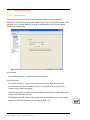
2.4.4 Connecting TalkSwitch to a LAN and/or PC
There are currently 4 ways to connect to TalkSwitch for PC configuration — over the
LAN (Ethernet port), USB, Serial, or Internet.
LAN: Use the provided Ethernet cable to connect TalkSwitch to the LAN
via your switch
USB: Use a USB cable to connect TalkSwitch to an available USB port on
your PC or USB hub.
Serial: Use a serial cable (RS232) to connect TalkSwitch to an available
Serial COM port on your PC.
Internet: The TalkSwitch 48-CA and CVA support remote configuration from a
PC via IP from a local or remote location.

Installing TalkSwitch 13
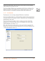
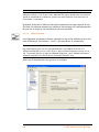
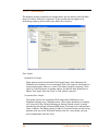
2.4.4.1 Connecting TalkSwitch to a LAN for local configuration
If you want to connect multiple TalkSwitch units to a LAN, please see section 2.5
To connect TalkSwitch to a LAN for configuration purposes, simply use the supplied
Category 5 cable with RJ45 connectors on either end. Connect TalkSwitch to the
switch. The top LED should light up to indicate a connection has been established with
a switch or hub.
If you are running Windows XP, please make sure you are not using Windows 98
compatibility mode.
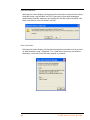
Any time TalkSwitch is being configured, it is ‘locked’ so that no other computer or
person using a phone can make configuration changes at the same time. If you leave
the software open for longer than 1 hour, TalkSwitch will automatically unlock itself
to allow configuration changes.
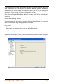
2.4.4.2 Connecting TalkSwitch to a PC using a USB cable
If you have an available USB port and cable, then connect TalkSwitch to the PC using a
USB cable (cable not provided).
Make sure you do not have any other communications programs running at the same
time you want to use the TalkSwitch configuration software. These may include Palm
Pilot, Hot Sync, TalkWorks, digital camera software. These programs tend to ‘hold’ onto
COM ports, making them unavailable for any other programs.
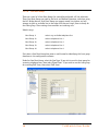
2.4.4.3 Connecting TalkSwitch to a PC using a Serial cable
If you have an available Serial port, then connect TalkSwitch to your PC using an RS-
232 Serial cable (cable not provided). By default, TalkSwitch is shipped with the Serial
and LAN ports enabled and the USB port disabled.
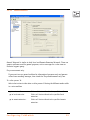
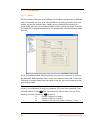
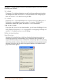
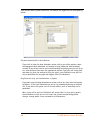
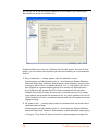
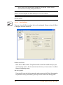
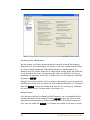
When you run the TalkSwitch software, select ‘Serial’ as the connection type then
select the Serial Port associated to this physical Serial port on your PC.
Make sure you do not have any other communications programs running at the same
time you want to use the TalkSwitch configuration software. These may include Palm
Pilot, Hot Sync, TalkWorks, digital camera software. These programs tend to ‘hold’ onto
COM ports, making them unavailable for any other programs.
If you are having problems communicating with TalkSwitch, please check the
Troubleshooting section of the manual.

14 TalkSwitch User Guide
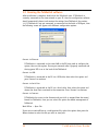
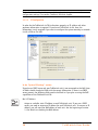
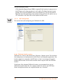
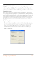
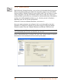
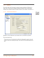
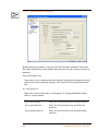
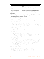
2.4.4.4 Connecting to TalkSwitch over IP
Ensure TalkSwitch is connected to a LAN with the supplied Category 5 cable. The top
LED should light up to indicate a connection has been established with a switch or
hub. To support remote configuration over IP, you will need to map port 9393 from
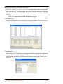
your firewall to TalkSwitch. Please refer to the router/firewall manual for activating
port forwarding.
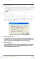
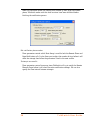
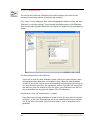
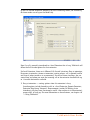
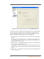
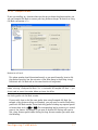
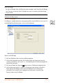
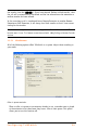
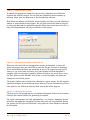
When you open the TalkSwitch software, you will be prompted to select your
connection type. Select ‘Internet’ then enter the public IP address of the TalkSwitch
location you wish to configure. You can click on ‘Address Book’ to maintain a list of
internet addresses.
Any time TalkSwitch is being configured, it is ‘locked’ so that no other computer or
person using a phone can make configuration changes at the same time. If you leave
the software open for longer than 1 hour, TalkSwitch will automatically unlock itself
to allow configuration changes.
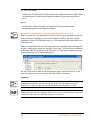
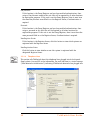
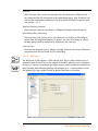
2.5 Using 2 or more TalkSwitch units on a LAN
If you have only one TalkSwitch unit, ignore this section and proceed to Section 3.
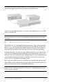
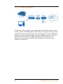
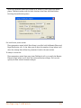
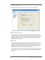
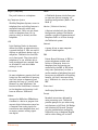
2.5.1 Connecting 2 or more TalkSwitch units to a LAN
TalkSwitch, CA and CVA units can be networked together on the same LAN. Ensure you
have the appropriate firmware on all units before adding units to the LAN. Check the
support section of our website for the latest updates.
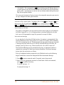
We recommend integrating your phone system into your existing LAN with an Ethernet
switch. A switch provides direct communication between TalkSwitch units, thus
keeping the TalkSwitch voice-over-LAN data isolated from other data on the network.
Page is loading ...
Page is loading ...
Page is loading ...
Page is loading ...
Page is loading ...
Page is loading ...
Page is loading ...
Page is loading ...
Page is loading ...
Page is loading ...
Page is loading ...
Page is loading ...
Page is loading ...
Page is loading ...
Page is loading ...
Page is loading ...
Page is loading ...
Page is loading ...
Page is loading ...
Page is loading ...
Page is loading ...
Page is loading ...
Page is loading ...
Page is loading ...
Page is loading ...
Page is loading ...
Page is loading ...
Page is loading ...
Page is loading ...
Page is loading ...
Page is loading ...
Page is loading ...
Page is loading ...
Page is loading ...
Page is loading ...
Page is loading ...
Page is loading ...
Page is loading ...
Page is loading ...
Page is loading ...
Page is loading ...
Page is loading ...
Page is loading ...
Page is loading ...
Page is loading ...
Page is loading ...
Page is loading ...
Page is loading ...
Page is loading ...
Page is loading ...
Page is loading ...
Page is loading ...
Page is loading ...
Page is loading ...
Page is loading ...
Page is loading ...
Page is loading ...
Page is loading ...
Page is loading ...
Page is loading ...
Page is loading ...
Page is loading ...
Page is loading ...
Page is loading ...
Page is loading ...
Page is loading ...
Page is loading ...
Page is loading ...
Page is loading ...
Page is loading ...
Page is loading ...
Page is loading ...
Page is loading ...
Page is loading ...
Page is loading ...
Page is loading ...
Page is loading ...
Page is loading ...
Page is loading ...
Page is loading ...
Page is loading ...
Page is loading ...
Page is loading ...
Page is loading ...
Page is loading ...
Page is loading ...
Page is loading ...
Page is loading ...
Page is loading ...
Page is loading ...
Page is loading ...
Page is loading ...
Page is loading ...
Page is loading ...
Page is loading ...
Page is loading ...
Page is loading ...
Page is loading ...
Page is loading ...
Page is loading ...
Page is loading ...
Page is loading ...
Page is loading ...
Page is loading ...
Page is loading ...
Page is loading ...
Page is loading ...
Page is loading ...
Page is loading ...
Page is loading ...
Page is loading ...
Page is loading ...
Page is loading ...
Page is loading ...
Page is loading ...
Page is loading ...
Page is loading ...
Page is loading ...
Page is loading ...
Page is loading ...
Page is loading ...
Page is loading ...
Page is loading ...
Page is loading ...
Page is loading ...
Page is loading ...
Page is loading ...
Page is loading ...
Page is loading ...
Page is loading ...
Page is loading ...
Page is loading ...
Page is loading ...
Page is loading ...
Page is loading ...
-
 1
1
-
 2
2
-
 3
3
-
 4
4
-
 5
5
-
 6
6
-
 7
7
-
 8
8
-
 9
9
-
 10
10
-
 11
11
-
 12
12
-
 13
13
-
 14
14
-
 15
15
-
 16
16
-
 17
17
-
 18
18
-
 19
19
-
 20
20
-
 21
21
-
 22
22
-
 23
23
-
 24
24
-
 25
25
-
 26
26
-
 27
27
-
 28
28
-
 29
29
-
 30
30
-
 31
31
-
 32
32
-
 33
33
-
 34
34
-
 35
35
-
 36
36
-
 37
37
-
 38
38
-
 39
39
-
 40
40
-
 41
41
-
 42
42
-
 43
43
-
 44
44
-
 45
45
-
 46
46
-
 47
47
-
 48
48
-
 49
49
-
 50
50
-
 51
51
-
 52
52
-
 53
53
-
 54
54
-
 55
55
-
 56
56
-
 57
57
-
 58
58
-
 59
59
-
 60
60
-
 61
61
-
 62
62
-
 63
63
-
 64
64
-
 65
65
-
 66
66
-
 67
67
-
 68
68
-
 69
69
-
 70
70
-
 71
71
-
 72
72
-
 73
73
-
 74
74
-
 75
75
-
 76
76
-
 77
77
-
 78
78
-
 79
79
-
 80
80
-
 81
81
-
 82
82
-
 83
83
-
 84
84
-
 85
85
-
 86
86
-
 87
87
-
 88
88
-
 89
89
-
 90
90
-
 91
91
-
 92
92
-
 93
93
-
 94
94
-
 95
95
-
 96
96
-
 97
97
-
 98
98
-
 99
99
-
 100
100
-
 101
101
-
 102
102
-
 103
103
-
 104
104
-
 105
105
-
 106
106
-
 107
107
-
 108
108
-
 109
109
-
 110
110
-
 111
111
-
 112
112
-
 113
113
-
 114
114
-
 115
115
-
 116
116
-
 117
117
-
 118
118
-
 119
119
-
 120
120
-
 121
121
-
 122
122
-
 123
123
-
 124
124
-
 125
125
-
 126
126
-
 127
127
-
 128
128
-
 129
129
-
 130
130
-
 131
131
-
 132
132
-
 133
133
-
 134
134
-
 135
135
-
 136
136
-
 137
137
-
 138
138
-
 139
139
-
 140
140
-
 141
141
-
 142
142
-
 143
143
-
 144
144
-
 145
145
-
 146
146
-
 147
147
-
 148
148
-
 149
149
-
 150
150
-
 151
151
-
 152
152
-
 153
153
-
 154
154
-
 155
155


Talkswitch TALKSWITCH 48-CA User manual
- Category
- IP phones
- Type
- User manual
- This manual is also suitable for
Ask a question and I''ll find the answer in the document
Finding information in a document is now easier with AI
Related papers
-
Talkswitch 48-CVA User manual
-
-
Centrepoint Technologies TalkSwitch 48 User manual
-
-
-
-
-
-
-
Other documents
-
 UNIFIED COMMUNICATIONS Call Forwarding Always feature Operating instructions
-
Panasonic KXTVP100E Operating instructions
-
-
Avaya IP Office Voicemail User manual
-
 Nextiva Cisco IP Phone User guide
-
 Voice Carrier Phone User manual
-
 tera-byte VoIP Phone User manual
-
Verizon Centrex User guide
-
-
Black Box Lineshare Pro FX150A User manual


