
MODEL G0694
20" X 43" HEAVY-DUTY
VARIABLE SPEED
WOOD LATHE
OWNER'S MANUAL
COPYRIGHT © JULY, 2009 BY GRIZZLY INDUSTRIAL, INC. REVISED MAY, 2013 (TR)
WARNING: NO PORTION OF THIS MANUAL MAY BE REPRODUCED IN ANY SHAPE
OR FORM WITHOUT THE WRITTEN APPROVAL OF GRIZZLY INDUSTRIAL, INC.
(FOR MODELS MANUFACTURED SINCE 10/09) #TRCRBLTSJB11817 PRINTED IN TAIWAN

This manual provides critical safety instructions on the proper setup,
operation, maintenance, and service of this machine/tool. Save this
document, refer to it often, and use it to instruct other operators.
Failure to read, understand and follow the instructions in this manual
may result in fire or serious personal injury—including amputation,
electrocution, or death.
The owner of this machine/tool is solely responsible for its safe use.
This responsibility includes but is not limited to proper installation in
a safe environment, personnel training and usage authorization,
proper inspection and maintenance, manual availability and compre-
hension, application of safety devices, cutting/sanding/grinding tool
integrity, and the usage of personal protective equipment.
The manufacturer will not be held liable for injury or property damage
from negligence, improper training, machine modifications or misuse.
Some dust created by power sanding, sawing, grinding, drilling, and
other construction activities contains chemicals known to the State
of California to cause cancer, birth defects or other reproductive
harm. Some examples of these chemicals are:
• Lead from lead-based paints.
• Crystalline silica from bricks, cement and other masonry products.
• Arsenic and chromium from chemically-treated lumber.
Your risk from these exposures varies, depending on how often you
do this type of work. To reduce your exposure to these chemicals:
Work in a well ventilated area, and work with approved safety equip-
ment, such as those dust masks that are specially designed to filter
out microscopic particles.

Table of Contents
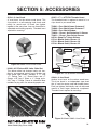
SECTION 5: ACCESSORIES ......................... 33
SECTION 6: MAINTENANCE ......................... 35
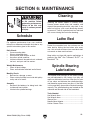
Schedule ...................................................... 35
Cleaning ....................................................... 35
Lathe Bed..................................................... 35
Spindle Bearing Lubrication ......................... 35
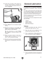
General Lubrication...................................... 37
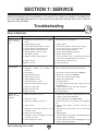
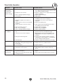
SECTION 7: SERVICE ................................... 39
Troubleshooting ........................................... 39
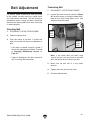
Belt Adjustment ............................................ 41
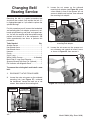
Changing Belt/Bearing Service .................... 42
SECTION 8: WIRING ...................................... 47
Wiring Safety Instructions ............................ 47
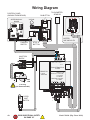
Wiring Diagram ............................................ 48
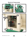
Electrical Components ................................. 49
SECTION 9: PARTS ....................................... 50
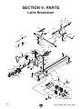
Lathe Breakdown ......................................... 50
Stand Breakdown......................................... 52
Stand Parts List ........................................... 53
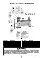
Labels & Cosmetics Breakdown .................. 54
WARRANTY AND RETURNS ........................ 57
INTRODUCTION ............................................... 2
Manual Accuracy ........................................... 2
Contact Info.................................................... 2
Machine Description ...................................... 2
Identification ................................................... 3
Machine Data Sheet ...................................... 4
SECTION 1: SAFETY ....................................... 6
Safety Instructions for Machinery .................. 6
Additional Safety for Wood Lathes ................ 8
SECTION 2: POWER SUPPLY ........................ 9
SECTION 3: SETUP ....................................... 11
Needed for Setup ......................................... 11
Unpacking .................................................... 11
Inventory ...................................................... 11
Cleanup ........................................................ 12
Site Considerations ...................................... 13
Moving & Placing Lathe ............................... 14
Mounting to Shop Floor ............................... 15
Test Run ...................................................... 16
SECTION 4: OPERATIONS ........................... 18
Basic Controls .............................................. 18
Operation Overview ..................................... 19
Stock Inspection & Requirements................ 19
Tailstock ....................................................... 20
Inboard Tool Rest ........................................ 20
Outboard Tool Rest ..................................... 21
Installing/Removing Headstock Center ........ 22
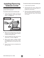
Installing/Removing Tailstock Center .......... 23
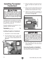
Installing Faceplate/Handwheel ................... 24
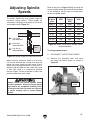
Adjusting Spindle Speeds ............................ 25
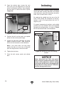
Indexing ....................................................... 26
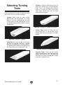
Selecting Turning Tools ............................... 27
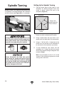
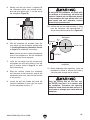
Spindle Turning ............................................ 28
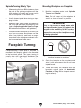
Faceplate Turning ........................................ 30
Outboard Turning ......................................... 31
Sanding/Finishing ........................................ 32

-2-
Model G0694 (Mfg. Since 10/09)
INTRODUCTION
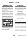
The G0694 20" x 43" Heavy-Duty Variable Speed
Wood Lathe is designed to turn wood stock so the
operator can remove material with a hand held
cutting tool called a chisel.
The variable speed control allows for infinite
spindle speed adjustment from 50–3,000 RPM
and the digital readout provides a precise reading
of the current spindle speed.
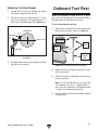
The outboard tool rest and double-sided spindle
allows for the turning of workpieces with diam-
eters larger than 20" on the outboard side of the
lathe.
Machine Description
Manual Accuracy
We are proud to offer this manual with your new
machine! We've made every effort to be exact
with the instructions, specifications, drawings,
and photographs of the machine we used when
writing this manual. However, sometimes we still
make
an occasional mistake.
Also, owing to our policy of continuous improve-
ment, your machine may not exactly match the
manual
.
If you find this to be the case, and the dif-
ference between the manual and machine leaves
you in doubt,
check our website for the latest
manual update or call technical support for help.
Before calling, find the manufacture date of your
machine by looking at the date stamped into the
machine ID label (see below). This will help us
determine if the manual version you received
matches the manufacture date of your machine.
For your convenience, we
post all available man
-
uals and
manual updates for free
on our website
at
www.grizzly.com. Any updates to your
model
of
machine will be reflected in these documents
as soon as they are complete.
Manufacture Date
of Your Machine
Contact Info
We stand behind our machines. If you have
any questions or need help, use the information
below to contact us. Before contacting, please get
the serial number and manufacture date of your
machine. This will help us help you faster.
Grizzly Technical Support
1203 Lycoming Mall Circle
Muncy, PA 17756
Phone: (570) 546-9663
Email: [email protected]
We want your feedback on this manual. What did
you like about it? Where could it be improved?
Please take a few minutes to give us feedback.
Grizzly Documentation Manager
P.O. Box 2069
Bellingham, WA 98227-2069
Email: [email protected]

Model G0694 (Mfg. Since 10/09)
-3-
Identification
To reduce the risk of
serious injury when using
this machine, read and
understand this entire
manual before beginning
any operations.
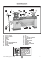
Figure 1. Identification.
A
B
C
D
E
F
G
I
J
K
M
L
N
O
P
Q
R
H
S
T
U
A. Outboard Tool Rest
B. Outboard Handwheel
C. Headstock
D. Faceplate
E. Spur Center
F. Bed
G. Tool Rest
H. Tool Rest Height Adjustment Lock
I. Tool Rest Holder Lock
J. Tailstock
K. Live Center
L. Quill
M. Quill Lock
N. Quill Adjustment Handwheel
O. Tailstock Base Lock
P. Stand
Q. RPM Digital Readout
R. Speed Dial
S. FWD/REV Switch
T. Emergency STOP Button
U. ON Button

-4-
Model G0694 (Mfg. Since 10/09)
The information contained herein is deemed accurate as of 5/7/2013 and represents our most recent product specifications.
Due to our ongoing improvement efforts, this information may not accurately describe items previously purchased.
PAGE 1 OF 2Model G0694
MACHINE DATA
SHEET
Customer Service #: (570) 546-9663 · To Order Call: (800) 523-4777 · Fax #: (800) 438-5901
MODEL G0694 20" X 43" HEAVY-DUTY VARIABLE SPEED
WOOD LATHE
Product Dimensions:
Weight.............................................................................................................................................................. 578 lbs.
Width (side-to-side) x Depth (front-to-back) x Height................................................................... 103 x 25 x 49-1/2 in.
Footprint (Length x Width)..................................................................................................................... 77 x 16-1/2 in.
Shipping Dimensions:
Type.......................................................................................................................................................... Wood Crate
Content........................................................................................................................................................... Machine
Weight.............................................................................................................................................................. 854 lbs.
Length x Width x Height....................................................................................................................... 26 x 84 x 56 in.
Must Ship Upright................................................................................................................................................... N/A
Electrical:
Power Requirement........................................................................................................... 220V, Single-Phase, 60 Hz
Prewired Voltage.................................................................................................................................................. 220V
Full-Load Current Rating.......................................................................................................................................... 9A
Minimum Circuit Size.............................................................................................................................................. 15A
Connection Type....................................................................................................................................... Cord & Plug
Power Cord Included.............................................................................................................................................. Yes
Power Cord Length................................................................................................................................................. 6 ft.
Power Cord Gauge......................................................................................................................................... 14 AWG
Plug Included........................................................................................................................................................... No
Recommended Plug Type..................................................................................................................................... 6-15
Switch Type.................................................................................................................... Push Button ON/OFF Switch
Inverter Type............................................................................................................................................ Delta VFD-E
Inverter Size......................................................................................................................................................... 3 HP
Motors:
Main
Type........................................................................................................................................... TEFC Induction
Horsepower................................................................................................................................................ 3 HP
Phase.................................................................................................................................................... 3-Phase
Amps.............................................................................................................................................................. 9A
Speed........................................................................................................................................... 50-1725 RPM
Bearings........................................................................................................ Sealed & Permanently Lubricated
Main Specifications:
Operation Information
Swing Over Bed......................................................................................................................................... 20 in.
Dist Between Centers................................................................................................................................ 43 in.
Swing Over Gap.................................................................................................................................. 24-7/8 in.
Swing Over Tool Rest................................................................................................................................ 16 in.
Swing Over Tool Rest Base................................................................................................................ 16-1/4 in.
No of Spindle Speeds............................................................................................................................ Variable
Spindle Speed Range................................................................................................................ 50 – 3000 RPM
Floor to Center Height............................................................................................................................... 45 in.
Machine Data Sheet

Model G0694 (Mfg. Since 10/09)
-5-
The information contained herein is deemed accurate as of 5/7/2013 and represents our most recent product specifications.
Due to our ongoing improvement efforts, this information may not accurately describe items previously purchased.
PAGE 2 OF 2Model G0694
Spindle Information
Spindle Taper............................................................................................................................................ MT#2
Spindle Thread Size.............................................................................................................................. 1-1/4 in.
Spindle TPI................................................................................................................................................ 8 TPI
Spindle Thread Direction.................................................................................................................. Right Hand
Type of Included Spindle Center................................................................................................................. Spur
Tool Rest Information
Tool Rest Width............................................................................................................................... 13-13/16 in.
Tool Rest Post Diameter....................................................................................................................... 1-1/4 in.
Tool Rest Post Length........................................................................................................................... 5-1/8 in.
Tool Rest Base Height......................................................................................................................... 2-1/16 in.
Tailstock Information
Tailstock Taper.......................................................................................................................................... MT#2
Type of Included Tailstock Center............................................................................................................... Live
Construction
Bed.......................................................................................................................... Precision-Ground Cast Iron
Stand...................................................................................................................................... Pre-Formed Steel
Headstock............................................................................................................................................ Cast Iron
Tailstock............................................................................................................................................... Cast Iron
Paint....................................................................................................................................................... Enamel
Features:
Single-Phase Inverter for 3-Phase Variable Speed Motor
Included Spur & Live Centers
13-3/4 in. Wide Outboard Tool Rest
Indexed Spindle Every 15 Degrees
3-Step Pulley System
Reversible Variable Speed Motor Control
Quick Release Belt Tension Lever for Quick Speed Range Changes

-6-
Model G0694 (Mfg. Since 10/09)
ELECTRICAL EQUIPMENT INJURY RISKS. You
can be shocked, burned, or killed by touching live
electrical components or improperly grounded
machinery. To reduce this risk, only allow qualified
service personnel to do electrical installation or
repair work, and always disconnect power before
accessing or exposing electrical equipment.
DISCONNECT POWER FIRST.
Always discon-
nect machine from power supply BEFORE making
adjustments, changing tooling, or servicing machine.
This prevents an injury risk from unintended startup
or contact with live electrical components.
EYE PROTECTION. Always wear ANSI-approved
safety glasses or a face shield when operating or
observing machinery to reduce the risk of eye
injury or blindness from flying particles. Everyday
eyeglasses are NOT approved safety glasses.
OWNER’S MANUAL. Read and understand this
owner’s manual BEFORE using machine.
TRAINED OPERATORS ONLY. Untrained oper-
ators have a higher risk of being hurt or killed.
Only allow trained/supervised people to use this
machine. When machine is not being used, dis-
connect power, remove switch keys, or lock-out
machine to prevent unauthorized use—especially
around children. Make workshop kid proof!
DANGEROUS ENVIRONMENTS. Do not use
machinery in areas that are wet, cluttered, or have
poor lighting. Operating machinery in these areas
greatly increases the risk of accidents and injury.
MENTAL ALERTNESS REQUIRED. Full mental
alertness is required for safe operation of machin-
ery. Never operate under the influence of drugs or
alcohol, when tired, or when distracted.
For Your Own Safety, Read Instruction
Manual Before Operating This Machine
The purpose of safety symbols is to attract your attention to possible hazardous conditions.
This manual uses a series of symbols and signal words intended to convey the level of impor-
tance of the safety messages. The progression of symbols is described below. Remember that
safety messages by themselves do not eliminate danger and are not a substitute for proper
accident prevention measures. Always use common sense and good judgment.
Indicates a potentially hazardous situation which, if not avoided,
MAY result in minor or moderate injury. It may also be used to alert
against unsafe practices.
Indicates a potentially hazardous situation which, if not avoided,
COULD result in death or serious injury.
Indicates an imminently hazardous situation which, if not avoided,
WILL result in death or serious injury.
This symbol is used to alert the user to useful information about
proper operation of the machine.
NOTICE
Safety Instructions for Machinery
SECTION 1: SAFETY

Model G0694 (Mfg. Since 10/09)
-7-
WEARING PROPER APPAREL. Do not wear
clothing, apparel or jewelry that can become
entangled in moving parts. Always tie back or
cover long hair. Wear non-slip footwear to avoid
accidental slips, which could cause loss of work-
piece control.
HAZARDOUS DUST. Dust created while using
machinery may cause cancer, birth defects, or
long-term respiratory damage. Be aware of dust
hazards associated with each workpiece material,
and always wear a NIOSH-approved respirator to
reduce your risk.
HEARING PROTECTION. Always wear hear-
ing protection when operating or observing loud
machinery. Extended exposure to this noise
without hearing protection can cause permanent
hearing loss.
REMOVE ADJUSTING TOOLS. Tools left on
machinery can become dangerous projectiles
upon startup. Never leave chuck keys, wrenches,
or any other tools on machine. Always verify
removal before starting!
USE CORRECT TOOL FOR THE JOB. Only use
this tool for its intended purpose—do not force
it or an attachment to do a job for which it was
not designed. Never make unapproved modifica-
tions—modifying tool or using it differently than
intended may result in malfunction or mechanical
failure that can lead to personal injury or death!
AWKWARD POSITIONS. Keep proper footing
and balance at all times when operating machine.
Do not overreach! Avoid awkward hand positions
that make workpiece control difficult or increase
the risk of accidental injury.
CHILDREN & BYSTANDERS. Keep children and
bystanders at a safe distance from the work area.
Stop using machine if they become a distraction.
GUARDS & COVERS. Guards and covers reduce
accidental contact with moving parts or flying
debris. Make sure they are properly installed,
undamaged, and working correctly.
FORCING MACHINERY. Do not force machine.
It will do the job safer and better at the rate for
which it was designed.
NEVER STAND ON MACHINE. Serious injury
may occur if machine is tipped or if the cutting
tool is unintentionally contacted.
STABLE MACHINE. Unexpected movement dur-
ing operation greatly increases risk of injury or
loss of control. Before starting, verify machine is
stable and mobile base (if used) is locked.
USE RECOMMENDED ACCESSORIES. Consult
this owner’s manual or the manufacturer for rec-
ommended accessories. Using improper acces-
sories will increase the risk of serious injury.
UNATTENDED OPERATION. To reduce the
risk of accidental injury, turn machine OFF and
ensure all moving parts completely stop before
walking away. Never leave machine running
while unattended.
MAINTAIN WITH CARE. Follow all maintenance
instructions and lubrication schedules to keep
machine in good working condition. A machine
that is improperly maintained could malfunction,
leading to serious personal injury or death.
CHECK DAMAGED PARTS. Regularly inspect
machine for any condition that may affect safe
operation. Immediately repair or replace damaged
or mis-adjusted parts before operating machine.
MAINTAIN POWER CORDS. When disconnect-
ing cord-connected machines from power, grab
and pull the plug—NOT the cord. Pulling the cord
may damage the wires inside. Do not handle
cord/plug with wet hands. Avoid cord damage by
keeping it away from heated surfaces, high traffic
areas, harsh chemicals, and wet/damp locations.
EXPERIENCING DIFFICULTIES. If at any time
you experience difficulties performing the intend-
ed operation, stop using the machine! Contact our
Technical Support at (570) 546-9663.

-8-
Model G0694 (Mfg. Since 10/09)
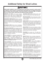
Additional Safety for Wood Lathes
INTEGRITY OF STOCK. Verify each workpiece
is free of knots, splits, nails, or foreign material
to ensure it can safely rotate on spindle without
breaking apart or causing turning tool kickback.
WORKPIECE PREPARATION. Before mounting,
cut off waste portions with a bandsaw or other tool
to ensure workpiece has no large edges to catch
turning tool, and it will rotate without dangerous
wobbling.
SECURING LOCKS. Verify tool rest, headstock,
and tailstock are secure before turning lathe ON.
SECURING WORKPIECE. An im pr op erly sec ured
workpiece can fly off spindle with deadly force.
Use proven setup techniques and always verify
workpiece is well-secured before starting lathe.
Only use high-quality fasteners with non-tapered
heads for faceplate attachment.
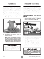
TOOL SUPPORT. An improperly supported tool
may be grabbed or ejected. Adjust tool rest
approximately
1
⁄4" away from workpiece and
1
⁄8"
above workpiece center line to provide proper
support for turning tool. Firmly hold turning tool
with both hands against tool rest.
TOOL KICKBACK. Occurs when turning tool is
ejected from workpiece with great force, striking
operator or bystanders. Commonly caused by
poor workpiece selection/preparation, improper
tool usage, or improper machine setup or tool rest
adjustment.
ADJUSTMENT TOOLS. Remove all chuck keys,
wrenches, and adjustment tools before turning
lathe ON. A tool left on the lathe can become a
deadly projectile when spindle is started.
SAFE CLEARANCES. Before starting spindle,
verify workpiece has adequate clearance by hand-
rotating it through its entire range of motion.
EYE/FACE PROTECTION. Always wear a face
shield and safety glasses when operating lathe.
PROPER APPAREL. Do not wear gloves, necktie
or loose clothing. Keep keep long hair away from
rotating spindle.
SPEED RATES. Select correct spindle speed for
workpiece size, type, shape, and condition. Use
low speeds when roughing or when turning large,
long, or non-concentric workpieces. Allow spindle
to reach full speed before turning.
NEW SETUPS. Test each new setup by starting
spindle rotation at the lowest speed and standing
to the side of the lathe until workpiece reaches full
speed and you can verify safe rotation.
ROUGHING. Use correct tool. Take light cuts,
use low speeds, and firmly support tool with both
hands.
SHARP TOOLS. Only use sharp turning tools—
they cut with less resistance than dull tools. Dull
turning tools can catch or grab and pull your
hands into the rotating workpiece.
STOPPING SPINDLE. Always allow spindle to
completely stop on its own. Never put hands or
another object on spinning workpiece.
ADJUSTMENTS/MAINTENANCE. Make sure
wood lathe is turned OFF, disconnected from
power, and all moving parts ar e co m p l et e l y sto p p e d
before doing adjustments or maintenance.
MEASURING WORKPIECE. Only measure work-
piece after it has stopped. Trying to measure a
spinning workpiece increases entanglement risk.
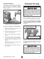
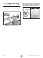
SANDING/POLISHING. To reduce entanglement
risk, remove tool rest before sanding. Never com-
pletely wrap sandpaper around workpiece.
MAIN INJURY HAZARDS: Death or crushing injury from getting entangled in rotating spindle
or workpiece; death, blindness, or broken bones from being struck by a workpiece that breaks
apart or comes loose during rotation, turning tool kickback, or flying wood chips. To minimize
your risk of these hazards, always heed the following warning information:

Model G0694 (Mfg. Since 10/09)
-9-
SECTION 2: POWER SUPPLY
Availability
Before installing the machine, consider the avail-
ability and proximity of the required power supply
circuit. If an existing circuit does not meet the
requirements for this machine, a new circuit must
be installed. To minimize the risk of electrocution,
fire, or equipment damage, installation work and
electrical wiring must be done by an electrican or
qualified service personnel in accordance with all
applicable codes and standards.
Electrocution, fire, or
equipment damage may
occur if machine is not
correctly grounded and
connected to the power
supply.
Full-Load Current Rating
The full-load current rating is the amperage a
machine draws at 100% of the rated output power.
On machines with multiple motors, this is the
amperage drawn by the largest motor or sum of all
motors and electrical devices that might operate
at one time during normal operations.
Full-Load Current Rating at 220V ....... 9 Amps
The full-load current is not the maximum amount
of amps that the machine will draw. If the machine
is overloaded, it will draw additional amps beyond
the full-load rating.
If the machine is overloaded for a sufficient length
of time, damage, overheating, or fire may result—
especially if connected to an undersized circuit.
To reduce the risk of these hazards, avoid over-
loading the machine during operation and make
sure it is connected to a power supply circuit that
meets the requirements in the following section.
Circuit Requirements for 220V
This machine is prewired to operate on a 220V
power supply circuit that has a verified ground and
meets the following requirements:
Nominal Voltage .............................. 220V/240V
Cycle ..........................................................60 Hz
Phase .................................................... 1-Phase
Power Supply Circuit ......................... 15 Amps
Plug/Receptacle ............................. NEMA 6-15
For your own safety and protection of
property, consult an electrician if you are
unsure about wiring practices or electrical
codes in your area.
Note: The circuit requirements listed in this man-
ual apply to a dedicated circuit—where only one
machine will be running at a time. If this machine
will be connected to a shared circuit where mul-
tiple machines will be running at the same time,
consult a qualified electrician to ensure that the
circuit is properly sized for safe operation.
A power supply circuit includes all electrical
equipment between the breaker box or fuse panel
in the building and the machine. The power sup-
ply circuit used for this machine must be sized to
safely handle the full-load current drawn from the
machine for an extended period of time. (If this
machine is connected to a circuit protected by
fuses, use a time delay fuse marked D.)

-10-
Model G0694 (Mfg. Since 10/09)
Extension Cords
We do not recommend using an extension cord
with this machine.
If you must use an extension
cord, only use it if absolutely necessary and only
on a temporary basis.
Extension cords cause voltage drop, which may
damage electrical components and shorten motor
life. Voltage drop increases as the extension cord
size gets longer and the gauge size gets smaller
(higher gauge numbers indicate smaller sizes).
Any extension cord used with this machine must
contain a ground wire, match the required plug
and receptacle, and meet the following require-
ments:
Minimum Gauge Size ...........................14 AWG
Maximum Length (Shorter is Better).......50 ft.
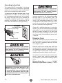
Grounding Instructions
This machine MUST be grounded. In the event
of certain malfunctions or breakdowns, grounding
reduces the risk of electric shock by providing a
path of least resistance for electric current.
Figure 2. Typical 6-15 plug and receptacle.
Grounding Prong
Current Carrying Prongs
6-15 PLUG
GROUNDED
6-15 RECEPTACLE
Improper connection of the equipment-grounding
wire can result in a risk of electric shock. The
wire with green insulation (with or without yellow
stripes) is the equipment-grounding wire. If repair
or replacement of the power cord or plug is nec-
essary, do not connect the equipment-grounding
wire to a live (current carrying) terminal.
Check with a qualified electrician or service per-
sonnel if you do not understand these grounding
requirements, or if you are in doubt about whether
the tool is properly grounded. If you ever notice
that a cord or plug is damaged or worn, discon-
nect it from power, and immediately replace it with
a new one.
Serious injury could occur if you connect
the machine to power before completing the
setup process. DO NOT connect to power
until instructed later in this manual.
The power cord and plug specified under “Circuit
Requirements for 220V”
on the previous page
has an equipment-grounding wire and a ground-
ing prong. The plug must only be inserted into
a matching receptacle (outlet) that is properly
installed and grounded in accordance with all
local codes and ordinances (see figure below).
No adapter should be used with the
required plug. If the plug does not fit the
available receptacle, or the machine must
be reconnected for use on a different type
of circuit, the reconnection must be made
by a qualified electrician and comply with all
local codes and ordinances.
Serious injury could occur if you connect
the machine to power before completing the
setup process. DO NOT connect to power
until instructed later in this manual.

Model G0694 (Mfg. Since 10/09)
-11-
SECTION 3: SETUP
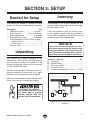
The following are needed to complete the setup
process, but are not included with your machine.
Description Qty
• Additional People .........................At Least 1
• Safety Glasses ............... 1 For Each Person
• Cleaner/Degreaser ..................... As Needed
• Disposable Shop Rags ............... As Needed
• Lifting Equipment (At Least 750 lb. Rating):
— Forklift or Hoist ....................................... 1
—Lifting Straps ........................................... 2
• Precision Level ........................................... 1
Needed for Setup
Inventory
Inventory: (Figure 3) Qty
A. Tool Rests .................................................. 2
B. Knockout Rod ............................................. 1
C. Spur Center MT#2 ...................................... 1
D. Live Center MT#2 ....................................... 1
E. T-Handle Hex Wrenches 3, 4mm ...... 1 Each
Figure 3. Model G0694 small component
inventory.
A
B
C
D
E
The following is a list of items shipped with your
machine. Before beginning setup, lay these items
out and inventory them.
If any non-proprietary parts are missing (e.g. a
nut or a washer), we will gladly replace them; or
for the sake of expediency, replacements can be
obtained at your local hardware store.
NOTICE
If you cannot find an item on this list, care-
fully check around/inside the machine and
packaging materials. Often, these items get
lost in packaging materials while unpack-
ing or they are pre-installed at the factory.
Your machine was carefully packaged for safe
transportation. Remove the packaging materials
from around your machine and inspect it. If you
discover any damage, please call us immediately
at (570) 546-9663
for advice.
Save the containers and all packing materials for
possible inspection by the carrier or its agent.
Otherwise, filing a freight claim can be difficult.
When you are completely satisfied with the condi-
tion of your shipment, inventory the contents.
Unpacking
SUFFOCATION HAZARD!
Keep children and pets away
from plastic bags or packing
materials shipped with this
machine. Discard immediately.

-12-
Model G0694 (Mfg. Since 10/09)
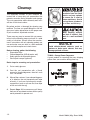
The unpainted surfaces of your machine are
coated with a heavy-duty rust preventative that
prevents corrosion during shipment and storage.
This rust preventative works extremely well, but it
will take a little time to clean.
Be patient and do a thorough job cleaning your
machine. The time you spend doing this now will
give you a better appreciation for the proper care
of your machine's unpainted surfaces.
There are many ways to remove this rust preven-
tative, but the following steps work well in a wide
variety of situations. Always follow the manufac-
turer’s instructions with any cleaning product you
use and make sure you work in a well-ventilated
area to minimize exposure to toxic fumes.
Before cleaning, gather the following:
• Disposable Rags
• Cleaner/degreaser (WD•40 works well)
• Safety glasses & disposable gloves
• Plastic paint scraper (optional)
Basic steps for removing rust preventative:
1.
Put on safety glasses.
2.
Coat the rust preventative with a liberal
amount of cleaner/degreaser, then let it soak
for 5–10 minutes.
3.
Wipe off the surfaces. If your cleaner/degreas-
er is effective, the rust preventative will wipe
off easily. If you have a plastic paint scraper,
scrape off as much as you can first, then wipe
off the rest with the rag.
4.
Repeat Steps 2–3 as necessary until clean,
then coat all unpainted surfaces with a quality
metal protectant to prevent rust.
Gasoline and petroleum
products have low flash
points and can explode
or cause fire if used to
clean machinery. Avoid
using these products
to clean machinery.
Many cleaning solvents
are toxic if inhaled. Only
work in a well-ventilated
area.
NOTICE
Avoid chlorine-based solvents, such as
acetone or brake parts cleaner, that may
damage painted surfaces.
T23692—Orange Power Degreaser
A great product for removing the waxy shipping
grease from your machine during clean up.
Figure 4. T23692 Orange Power Degreaser.
Cleanup

Model G0694 (Mfg. Since 10/09)
-13-
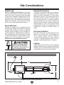
Site Considerations
Weight Load
Refer to the Machine Data Sheet for the weight
of your machine. Make sure that the surface upon
which the machine is placed will bear the weight
of the machine, additional equipment that may be
installed on the machine, and the heaviest work-
piece that will be used. Additionally, consider the
weight of the operator and any dynamic loading
that may occur when operating the machine.
Space Allocation
Consider the largest size of workpiece that will
be processed through this machine and provide
enough space around the machine for adequate
operator material handling or the installation of
auxiliary equipment. With permanent installations,
leave enough space around the machine to open
or remove doors/covers as required by the main-
tenance and service described in this manual.
See below for required space allocation.
Physical Environment
The physical environment where the machine is
operated is important for safe operation and lon-
gevity of machine components. For best results,
operate this machine in a dry environment that is
free from excessive moisture, hazardous chemi-
cals, airborne abrasives, or extreme conditions.
Extreme conditions for this type of machinery are
generally those where the ambient temperature
range exceeds 41°–104°F; the relative humidity
range exceeds 20–95% (non-condensing); or the
environment is subject to vibration, shocks, or
bumps.
Electrical Installation
Place this machine near an existing power source.
Make sure all power cords are protected from
traffic, material handling, moisture, chemicals,
or other hazards. Make sure to leave access to
a means of disconnecting the power source or
engaging a lockout/tagout device, if required.
Lighting
Lighting around the machine must be adequate
enough that operations can be performed safely.
Shadows, glare, or strobe effects that may distract
or impede the operator must be eliminated.
Children or untrained people
may be seriously injured by
this machine. Only install in an
access restricted location.
Figure 5. Minimum working clearances.
Wall
220V Single-Phase
Power Source
30"
100"
28"
17"

-14-
Model G0694 (Mfg. Since 10/09)
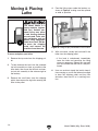
Moving & Placing
Lathe
The Model G0694 is a
heavy machine (approx.
580 lbs.) Serious per-
sonal injury may occur
if safe moving methods
are not used. To be safe,
get assistance and use
power lifting equipment
rated for at least 750 lbs.
to move the shipping
crate and remove the
machine from the crate.
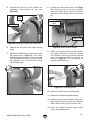
To move and place your lathe:
1. Remove the top crate from the shipping pal-
let.
2. To help balance the load, lock the outboard
tool rest assembly as close as possible to the
lathe body, then move the tailstock and cen-
ter tool rest assembly to the extreme right of
the bedway.
3. Remove the small items from the shipping
pallet, then remove the lag bolts securing the
lathe to the pallet.
Figure 6. Lifting straps positioned to lift the lathe.
4. Feed the lifting straps under the bedway, as
shown in Figure 6, making sure they spread
as wide as possible.
5. With assistance, steady the load and lift the
lathe from the shipping pallet.
— If the load is unbalanced, immediately
lower the lathe and reposition the lifting
straps as necessary. Repeat this step until
you are satisfied that the load is safely bal-
anced.
6. Have an assistant steady the load to keep it
from swaying as you lift the lathe only enough
to clear the shipping pallet and any floor
obstacles, then move it to its working loca-
tion.

Model G0694 (Mfg. Since 10/09)
-15-
Mounting to Shop
Floor
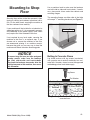
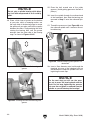
NOTICE
To ensure long life from you lathe and good
turning results, make sure the bedways
are level side-to-side and front-to-back.
Re-check the bedways two weeks after the
initial placement of the machine, then annu-
ally thereafter.
Figure 7. Right side mounting flange.
Mounting Flange
Use a precision level to make sure the bedways
are level side-to-side and front-to-back. If neces-
sary, place metal shims under the cabinets and
mounting flanges.
The mounting flanges on either side of the lathe
will accept
3
⁄8" mounting hardware (see Figure 7).
Securing the machine to the floor prevents it from
tipping or shifting and reduces operational vibra-
tion. On the other hand, securing the machine to
the floor reduces future mobility.
If your machine will be installed in an industrial or
workplace setting, or if it is permanently connect-
ed (hardwired) to the power supply, local codes
may require that it be fastened to the floor.
If not required by any local codes, securing the
machine to the floor is an optional step. If you
choose not to secure the machine to the floor,
we recommend placing it on machine mounts,
because they give you an easy way to level the
machine and feature vibration-absorbing pads.
Figure 8. Typical fasteners for mounting to
concrete floors.
Machine Base
Concrete
Lag Screw
Lag Shield Anchor
Flat Washer
Drilled Hole
Bolting to Concrete Floors
Lag shield anchors with lag screws (see below)
are a popular way to anchor machinery to a con-
crete floor. However, always be sure the approved
methodology when local codes apply.

-16-
Model G0694 (Mfg. Since 10/09)
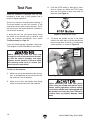
Before starting the lathe, you must read
through the rest of the manual and be famil-
iar with the various functions and safety
features on this machine. Failure to follow
this warning could result in serious per-
sonal injury or even death!
Test Run
Once the assembly is complete, test run your
machine to make sure it runs properly and is
ready for regular operation.
The test run consists of verifying the following: 1)
The motor powers up and runs correctly, 2) the
stop button safety feature works correctly, and 3)
the motor turns the correct direction (machine is
not wired out of phase).
If, during the test run, you cannot easily locate
the source of an unusual noise or vibration, stop
using the machine immediately, then review
Troubleshooting on Page 39.
If you still cannot remedy a problem, contact our
Tech Support at (570) 546-9663 for assistance.
To test run the machine:
1. Make sure you understand the safety instruc-
tions at the beginning of the manual and that
the machine is set up properly.
2. Make sure all tools and objects used during
setup are cleared away from the machine.
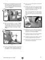
Figure 9. Resetting the switch.
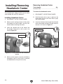
4. To unlock the spindle so that it can freely
rotate in the next steps, pull the spindle lock
lever out and rotate it so that it is in the twelve
o'clock position, as shown in Figure 10.
Always disconnect the lathe from power
before using the spindle lock feature. Never
resume turning operations without making
sure that the spindle lock is disengaged and
the spindle turns freely by hand. Otherwise
personal injury or property damage could
result.
Figure 10. Unlocking the spindle.
Spindle
Lock
Lever
3. Push the STOP button in, then twist it clock-
wise so it pops out. When the STOP button
pops out, the switch is reset and ready for
operation (see Figure 9).

Model G0694 (Mfg. Since 10/09)
-17-
5. Turn the speed dial counterclockwise to set
the spindle speed at zero.
6. Connect the lathe to power.
7. Verify that the machine is operating cor-
rectly by pushing the ON button, then use the
speed dial to increase the spindle speed.
—When operating correctly, the machine
runs smoothly with little or no vibration or
rubbing noises.
— Investigate and correct strange or unusual
noises or vibrations before operating the
machine further. Always stop the machine
and disconnect it from power before inves-
tigating or correcting potential problems.
8. Press the STOP button to stop the machine.
9. WITHOUT resetting the switch, press the ON
button. The machine should not start.
—If the machine does not start, the STOP
button safety feature is working correctly.
—If the machine does start (with the STOP
button pushed in), immediately disconnect
power to the machine. The STOP button
safety feature is not working correctly. This
safety feature must work properly before
proceeding with regular operations. Call
Tech Support for help.
10. Verify that the power is not connected out of
phase by starting/stopping the machine in the
FWD direction and determining if the spindle
turns in the counterclockwise direction (look-
ing at the spindle from the tailstock side of the
lathe).
— If the spindle does NOT turn counter-
clockwise, it is turning in the wrong direc-
tion. Stop the machine, disconnect it from
power, then swap any two of the three
power wires inside the motor wiring junc-
tion box (refer to the Wiring Diagram on
Page 48 for specific information).

-18-
Model G0694 (Mfg. Since 10/09)
SECTION 4: OPERATIONS
To reduce the risk of
serious injury when using
this machine, read and
understand this entire
manual before beginning
any operations.
Loose hair and clothing
could get caught in the
lathe and cause serious
personal injury. Keep
loose clothing and long
hair away from moving
parts of lathe.
Damage to your eyes and lungs could result
from using this machine without proper pro-
tective gear. Always wear a face shield and
respirator when operating this machine.
NOTICE
If you have never used this type of machine
or equipment before, WE STRONGLY REC-
OMMEND that you read books, review
industry trade magazines, or get formal
training before beginning any projects.
Regardless of the content in this section,
Grizzly Industrial will not be held liable for
accidents caused by lack of training.
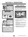
A. ON Button: Starts the spindle rotation.
B. Emergency STOP Button: Turns the spindle
rotation OFF.
C. Speed Dial: Adjusts the spindle speed from
low to high within the range governed by the
pulley belt position.
D. FWD/REV Switch: Toggles the spindle direc-
tion between clockwise or counterclockwise.
E. RPM Digital Readout: Indicates the spindle
speed in RPM (rotations per minute).
Basic Controls
Figure 11. Control panel.
A
B
C
D
E
See Figure 11 and refer to the list of controls
below to familiarize yourself with the lathe con-
trols. You will find that understanding the names
and descriptions of the controls is useful when
reading this operations section.
Page is loading ...
Page is loading ...
Page is loading ...
Page is loading ...
Page is loading ...
Page is loading ...
Page is loading ...
Page is loading ...
Page is loading ...
Page is loading ...
Page is loading ...
Page is loading ...
Page is loading ...
Page is loading ...
Page is loading ...
Page is loading ...
Page is loading ...
Page is loading ...
Page is loading ...
Page is loading ...
Page is loading ...
Page is loading ...
Page is loading ...
Page is loading ...
Page is loading ...
Page is loading ...
Page is loading ...
Page is loading ...
Page is loading ...
Page is loading ...
Page is loading ...
Page is loading ...
Page is loading ...
Page is loading ...
Page is loading ...
Page is loading ...
Page is loading ...
Page is loading ...
Page is loading ...
Page is loading ...
-
 1
1
-
 2
2
-
 3
3
-
 4
4
-
 5
5
-
 6
6
-
 7
7
-
 8
8
-
 9
9
-
 10
10
-
 11
11
-
 12
12
-
 13
13
-
 14
14
-
 15
15
-
 16
16
-
 17
17
-
 18
18
-
 19
19
-
 20
20
-
 21
21
-
 22
22
-
 23
23
-
 24
24
-
 25
25
-
 26
26
-
 27
27
-
 28
28
-
 29
29
-
 30
30
-
 31
31
-
 32
32
-
 33
33
-
 34
34
-
 35
35
-
 36
36
-
 37
37
-
 38
38
-
 39
39
-
 40
40
-
 41
41
-
 42
42
-
 43
43
-
 44
44
-
 45
45
-
 46
46
-
 47
47
-
 48
48
-
 49
49
-
 50
50
-
 51
51
-
 52
52
-
 53
53
-
 54
54
-
 55
55
-
 56
56
-
 57
57
-
 58
58
-
 59
59
-
 60
60


Ask a question and I''ll find the answer in the document
Finding information in a document is now easier with AI
Related papers
-
Grizzly Lathe G0632 User manual
-
-
-
-
-
-
-
-
-
 Grizzly Industrial G0462 Owner's manual

Other documents
-
Craftsman 351.217160 Owner's manual
-
Bellaterra Home BT4801-GY Installation guide
-
-
-
 Grizzly Industrial G0694 User manual
-
 Grizzly Industrial G0733 User manual
-
 Grizzly Industrial G0838 User manual
-
King Canada KWL-1443VS User manual
-
Craftex CX Series CX802 Owner's manual
-


