Operating Instructions
Page 2 of 2
CRT2 Room Thermostat Battery Operated
10. High and Low temperature limitation
16. Replacing the batteries
OFF
Set
ON
Limit
OFF
Limit
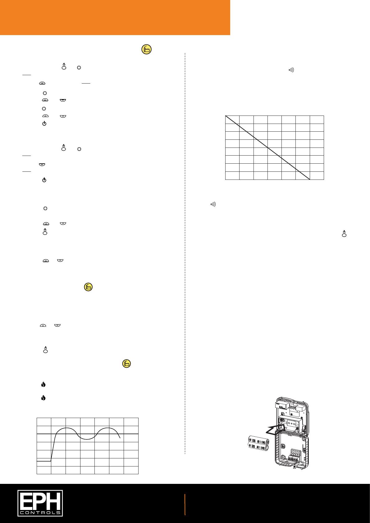
15. Delay start control mode
Delay start is an energy saving mode.
When the delay start function is active the symbol will appear on the
screen. When in this mode the activation of the thermostat is delayed by a
variable time depending on the current temperature, setpoint temperature
and also the fall in temperature from when the delay start has activated.
See graph (15.1) Delay Start Control.
The symbol will show until the thermostat activates.
When activated the thermostat will allow the heating system time to reach
the setpoint and delay start will remain inactive until it reaches this setpoint.
Delay start can be reactivated by:
Lowering the setpoint below the current temperature, pressing the
‘standby’ button to set the temperature, then raising the setpoint above the
zone temperature within 6˚C of the setpoint.
The heating will be delayed as per the line on the graph.
If the dierence between the actual temperature and the setpoint is 1C the
thermostat will delay starting for circa 40 minutes.
If the dierence between the actual temperature and the setpoint is 3C the
thermostat will delay starting for circa 24 minutes.
If the dierence is 6C or more, the heating will be switched on immediately.
The time delay will change if the temperature drops from the original
calculation.
To deactivate Delay Start, see section 13.
48.0
42.0
36.0
30.0
24.0
18.0
12.0
6.0
0.0
0123456
Temperature below thermostat setting °C
Time delay after Delay Start activated in minutes
Graph (15.1): Delay Start Control
Slacken the fastening screw on the bottom of the thermostat with a
philips head screwdriver.
The thermostat is hinged and can be opened 180 degrees.
Replace the batteries with 2 x AA Alkaline batteries.
Close the thermostat and tighten the fastening screw.
An upper and lower temperature limit may be chosen.
Press and hold the and buttons for 10 seconds.
will appear on the screen.
Use the button to select .
Press the button to select high limit.
Press the and buttons to select high limit temperature.
Press the button to select low limit.
Press the and buttons to select low limit temperature.
Press the button and the thermostat is ready for operation.
Limit will appear on the screen.
To deactivate High and Low temperature limitation.
Press and hold the and buttons for 10 seconds.
will appear on the screen.
Use the button to deactivate this function.
will appear on the screen.
Press the button and the thermostat is ready for operation.
Set
Set
Set
ON
Limit
OFF
Limit
11. Adjusting the switching dierential (Normal + DS)
12. Adjusting the setpoint temperature
Press the button once, Di set will appear on the screen.
The factory default switching dierential of 0.4C will appear on the screen.
Press the and buttons to select the desired dierential from 0.2 - 1˚C.
Press the button to return to normal operation.
Set
Press the or buttons to adjust the temperature setpoint.
13. Changing the thermostat mode
P0 - Normal On/O mode
P1 - Delay Start mode
Press the ‘Reset’ button at the side of the thermostat.
P0 will appear on the screen.
Use the or buttons to change between P0 and P1.
Select P0 for normal operation.
Select P1 for delay start.
Press the ‘standby’ button to conrm.
14. Normal control mode (On/O )
When the temperature falls below the setpoint temperature, the ame
symbol will appear and the thermostat will switch on.
When the temperature rises above the setpoint temperature, the ame
symbol will disappear and the thermostat will switch o.
22˚C
21˚C
20˚C
19˚C
18˚C
17˚C
Temp
Time Minutes
Graph (14.1): On / O Control
Setpoint Temperature
200 40 60 80 100
20221104_CRT2_OpIns_PK
EPH Controls Ireland
technical@ephcontrols.com www.ephcontrols.com
EPH Controls UK
technical@ephcontrols.co.uk www.ephcontrols.co.uk