Page is loading ...

USER GUIDE
Trimble® SPS882
Smart GPS Antenna


Version 4.00
Revision A
May 2009 F
USER GUIDE
Trimble® SPS882 Smart GPS Antennas

Corporate Office
Trimble Navigation Limited
935 Stewart Drive
Sunnyvale, CA 94085
USA
www.trimble.com
Construction Business Area
Trimble Navigation Limited
Construction Business Area
5475 Kellenburger Road
Dayton, Ohio 45424-1099
USA
800-538-7800 (toll free in USA)
+1-937-245-5600 Phone
+1-937-233-9004 Fax
www.trimble.com
E-mail: [email protected]
Legal Notices
Copyright and Trademarks
© 2006–2009, Trimble Navigation Limited. All rights reserved.
Trimble and the Globe & Triangle logo are trademarks of Trimble
Navigation Limited, registered in the United States Patent and
Trademark Office and in other countries. AutoBase, CMR, CMR+,
HYDROpro, Maxwell, SiteNet, TRIMMARK, TRIMTALK, Trimble
Geomatics Office, Trimble Total Control, TSC2, VRS, Zephyr, and
Zephyr Geodetic are trademarks of Trimble Navigation Limited.
The Bluetooth word mark and logos are owned by the Bluetooth
SIG, Inc. and any use of such marks by Trimble Navigation Limited
is under license.
Microsoft, Windows, and Windows NT, are either registered
trademarks or trademarks of Microsoft Corporation in the United
States and/or other countries.
All other trademarks are the property of their respective owners.
Release Notice
This is the May 2009 release (Revision A) of the SPS882 Smart GPS
Antenna User Guide. It applies to version 4.00 of the SPS882 Smart
GPS antenna.
Product Limited Warranty Information
For applicable product Limited Warranty information, please refer to the
Limited Warranty Card included with this Trimble product, or consult
your local Trimble authorized dealer.
Notices
Class B Statement – Notice to Users. This equipment has been
tested and found to comply with the limits for a Class B digital
device, pursuant to Part 15 of the FCC rules. These limits are
designed to provide reasonable protection against harmful
interference in a residential installation. This equipment generates,
uses, and can radiate radio frequency energy and, if not installed
and used in accordance with the instructions, may cause harmful
interference to radio communication. However, there is no
guarantee that interference will not occur in a particular
installation. If this equipment does cause harmful interference to
radio or television reception, which can be determined by turning
the equipment off and on, the user is encouraged to try to correct
the interference by one or more of the following measures:
– Reorient or relocate the receiving antenna.
– Increase the separation between the equipment and the receiver.
– Connect the equipment into an outlet on a circuit different from
that to which the receiver is connected.
– Consult the dealer or an experienced radio/TV technician for
help.
Changes and modifications not expressly approved by the
manufacturer or registrant of this equipment can void your
authority to operate this equipment under Federal
Communications Commission rules.
Europe
This product has been tested and found to comply with the
requirements for a Class B device pursuant to European
Council Directive , thereby satisfying the requirements for
CE Marking and sale within the European Economic Area (EEA).
Contains Infineon radio module . These requirements are designed
to provide reasonable protection against harmful interference when
the equipment is operated in a residential or commercial
environment.
Australia and New Zealand
This product conforms with the regulatory requirements of
the Australian Communications Authority (ACA) EMC
framework, thus satisfying the requirements for C-Tick
Marking and sale within Australia and New Zealand.
Taiwan – Battery Recycling Requirements
The product contains a removable Lithium-ion battery.
Taiwanese regulations require that waste batteries are
recycled.
廢電池請回收
Notice to Our European Union Customers
Restriction of Use of Certain Hazardous Substances
in Electrical and Electronic Equipment (RoHS)
This Trimble product complies in all material respects with
DIRECTIVE 2002/95/EC OF THE EUROPEAN PARLIAMENT AND
OF THE COUNCIL of 27 January 2003 on the restriction of the use of
certain hazardous substances in electrical and electronic
equipment (RoHS Directive) and Amendment 2005/618/EC filed
under C(2005) 3143, with exemptions for lead in solder pursuant to
Paragraph 7 of the Annex to the RoHS Directive applied.
Waste Electrical and Electronic Equipment (WEEE)
For product recycling instructions and more information, please go
to www.trimble.com/ev.shtml.
Recycling in Europe: To recycle Trimble WEEE (Waste
Electrical and Electronic Equipment, products that run on
electrical power.), Call +31 497 53 24 30, and ask for the
"WEEE Associate". Or, mail a request for recycling
instructions to:
Trimble Europe BV
c/o Menlo Worldwide Logistics
Meerheide 45
5521 DZ Eersel, NL

SPS882 Smart GPS Antenna User Guide 3
Safety Information
Before you use your Trimble® SPS GPS receiver, make sure that you have read and
understood all safety requirements.
Regulations and safety
The receivers contain an internal radio-modem and can send signals through
Bluetooth® wireless technology or through an external data communications radio.
Regulations regarding the use of the 450 MHz radio-modems vary greatly from country
to country. In some countries, the unit can be used without obtaining an end-user
license. Other countries require end-user licensing. For licensing information, consult
your local Trimble dealer. Bluetooth and 900 MHz radio-modems operate in
license-free bands.
Before operating an SPS882 Smart GPS antenna, determine if authorization or a
license to operate the unit is required in your country. It is the responsibility of the end
user to obtain an operator’s permit or license for the receiver for the location or
country of use.
For FCC regulations, see Notices, page 2.
Type approval
Type approval, or acceptance, covers technical parameters of the equipment related to
emissions that can cause interference. Type approval is granted to the manufacturer of
the transmission equipment, independent from the operation or licensing of the units.
Some countries have unique technical requirements for operation in particular
radio-modem frequency bands. To comply with those requirements, Trimble may have
modified your equipment to be granted Type approval. Unauthorized modification of
the units voids the Type approval, the warranty, and the operational license of the
equipment.
Exposure to radio frequency radiation
For 450 MHz radio
Safety. Exposure to RF energy is an important safety consideration. The FCC has
adopted a safety standard for human exposure to radio frequency electromagnetic
energy emitted by FCC regulated equipment as a result of its actions in General Docket
79-144 on March 13, 1986.
Proper use of this radio modem results in exposure below government limits. The
following precautions are recommended:
•DO NOT operate the transmitter when someone is within 20 cm (7.8 inches) of
the antenna.
•DO NOT operate the transmitter unless all RF connectors are secure and any
open connectors are properly terminated.

Safety Information
4 SPS882 Smart GPS Antenna User Guide
•DO NOT operate the equipment near electrical blasting caps or in an explosive
atmosphere.
•All equipment must be properly grounded according to Trimble installation
instructions for safe operation.
•All equipment should be serviced only by a qualified technician.
For license-free 900 MHz radio1
CCAUTION – For your own safety, and in terms of the RF exposure requirements of the
FCC, always observe the precautions listed here.
•DO NOT operate the transmitter when someone is within 20 cm (7.8 inches) of
the antenna.
•The minimum operating distance between an SPS882 with an internal 900 Mhz
radio transmitter and a SPS882 900 Mhz rover is 0.6 m (2 ft).
•Do not co-locate the antenna with any other transmitting device.
For Bluetooth radio
The radiated output power of the internal Bluetooth wireless radio is far below the
FCC radio frequency exposure limits. Nevertheless, the wireless radio shall be used in
such a manner that the Trimble receiver is 20 cm or further from the human body. The
internal wireless radio operates within guidelines found in radio frequency safety
standards and recommendations, which reflect the consensus of the scientific
community. Trimble therefore believes that the internal wireless radio is safe for use by
consumers. The level of energy emitted is far less than the electromagnetic energy
emitted by wireless devices such as mobile phones. However, the use of wireless radios
may be restricted in some situations or environments, such as on aircraft. If you are
unsure of restrictions, you are encouraged to ask for authorization before turning on
the wireless radio.
Installing antennas
CCAUTION – For your own safety, and in terms of the RF exposure requirements of the
FCC, always observe these precautions:
– Always maintain a minimum separation distance of 20 cm (7.8 inches) between yourself
and the radiating antenna.
– Do not co-locate the antenna with any other transmitting device.
CCAUTION – The GPS antenna and its cabling should be installed in accordance with all
national and local electrical codes, regulations, and practices.
The antenna and cabling should be installed where they will not become energized as a
result of falling nearby power lines, nor be mounted where they are subjected to
overvoltage transients, particularly lightning. Such installations require additional
protective means that are detailed in national and local electrical codes.
1. 900 MHz radios are not used in Europe.

SPS882 Smart GPS Antenna User Guide 5
Safety Information
This device has been designed to operate with the antennas listed below. Antennas not
included in this list are strictly prohibited for use with this device. The required
antenna impedance is 50 ohms.
The antennas that can be used (country dependent) with the 450 MHz radio are 0 dBi
and 5 dBi whip antennas. The antennas that can be used (country dependent) with the
900 MHz radio are 0 dBi, 3 dBi, and 5 dBi whip antennas.
To reduce potential radio interference to other users, the antenna type and its gain
should be so chosen so that the equivalent isotropically radiated power (e.i.r.p.) is not
more than that permitted for successful communication.
Battery safety
CWARNING – Do not damage the rechargeable Lithium-ion battery. A damaged battery
can cause an explosion or fire, and can result in personal injury and/or property damage.
To prevent injury or damage:
– Do not use or charge the battery if it appears to be damaged. Signs of damage include,
but are not limited to, discoloration, warping, and leaking battery fluid.
– Do not expose the battery to fire, high temperature, or direct sunlight.
– Do not immerse the battery in water.
– Do not use or store the battery inside a vehicle during hot weather.
– Do not drop or puncture the battery.
– Do not open the battery or short-circuit its contacts.
CWARNING – Avoid contact with the rechargeable Lithium-ion battery if it appears to be
leaking. Battery fluid is corrosive, and contact with it can result in personal injury and/or
property damage.
To prevent injury or damage:
– If the battery leaks, avoid contact with the battery fluid.
– If battery fluid gets into your eyes, immediately rinse your eyes with clean water and
seek medical attention. Do not rub your eyes!
– If battery fluid gets onto your skin or clothing, immediately use clean water to wash off
the battery fluid.
CWARNING – Charge and use the rechargeable Lithium-ion battery only in strict
accordance with the instructions. Charging or using the battery in unauthorized
equipment can cause an explosion or fire, and can result in personal injury and/or
equipment damage.
To prevent injury or damage:
– Do not charge or use the battery if it appears to be damaged or leaking.
– Charge the Lithium-ion battery only in a Trimble product that is specified to charge it.
Be sure to follow all instructions that are provided with the battery charger.
– Discontinue charging a battery that gives off extreme heat or a burning odor.
– Use the battery only in Trimble equipment that is specified to use it.
– Use the battery only for its intended use and according to the instructions in the product
documentation.
Changing the radio module
Trimble recommends that you do not change from one version of a radio door
assembly to another, for the following reasons:

Safety Information
6 SPS882 Smart GPS Antenna User Guide
•The internal connector on the radio is not intended for multiple insertions or
extractions. It will break.
•The seal integrity of the whole GPS receiver is compromised when the radio is
removed. Users do not have the facilities to test the integrity of the seal.
•If the unit is outside of warranty, you can purchase another radio door, which
must be installed by a Trimble authorized Service Provider. There are hardware
limitations to this, so be very careful, especially with the 900 MHz doors.
CCAUTION – Because of installation problems and country regulation issues, Trimble does
not sell radio doors to end users. Trimble authorized Service Providers must comply with
country regulations and install the correct radio only in defined and accepted receivers.
Installing a radio in a non-specified GPS product or device voids any warranty of the radio
and of the GPS product. It also subjects the service provider to penalties set forth by
various government agencies. Trimble shall assume no liability for radios used in
non-authorized products.

SPS882 Smart GPS Antenna User Guide 7
Contents
Safety Information . . . . . . . . . . . . . . . . . . . . . . . . . . . . . . . . 3
Regulations and safety . . . . . . . . . . . . . . . . . . . . . . . . . . . . . . . . . . . . . . . . . . . . . . . 3
Type approval . . . . . . . . . . . . . . . . . . . . . . . . . . . . . . . . . . . . . . . . . . . . . . . . . . . . 3
Exposure to radio frequency radiation. . . . . . . . . . . . . . . . . . . . . . . . . . . . . . . . . . . . . 3
For 450 MHz radio . . . . . . . . . . . . . . . . . . . . . . . . . . . . . . . . . . . . . . . . . . . . . 3
For license-free 900 MHz radio . . . . . . . . . . . . . . . . . . . . . . . . . . . . . . . . . . . . . 4
For Bluetooth radio . . . . . . . . . . . . . . . . . . . . . . . . . . . . . . . . . . . . . . . . . . . . 4
Installing antennas . . . . . . . . . . . . . . . . . . . . . . . . . . . . . . . . . . . . . . . . . . . . . . . . . 4
Battery safety. . . . . . . . . . . . . . . . . . . . . . . . . . . . . . . . . . . . . . . . . . . . . . . . . . . . . 5
Changing the radio module. . . . . . . . . . . . . . . . . . . . . . . . . . . . . . . . . . . . . . . . . . . . 5
1 Introduction . . . . . . . . . . . . . . . . . . . . . . . . . . . . . . . . . . . 11
About the SPS882 Smart GPS antenna. . . . . . . . . . . . . . . . . . . . . . . . . . . . . . . . . . . . 11
Related information . . . . . . . . . . . . . . . . . . . . . . . . . . . . . . . . . . . . . . . . . . . . . . . 11
Technical support. . . . . . . . . . . . . . . . . . . . . . . . . . . . . . . . . . . . . . . . . . . . . . . . . 11
Your comments . . . . . . . . . . . . . . . . . . . . . . . . . . . . . . . . . . . . . . . . . . . . . . . . . . 12
2 Features and Functions . . . . . . . . . . . . . . . . . . . . . . . . . . . . . 13
Standard features . . . . . . . . . . . . . . . . . . . . . . . . . . . . . . . . . . . . . . . . . . . . . . . . . 14
Use and care . . . . . . . . . . . . . . . . . . . . . . . . . . . . . . . . . . . . . . . . . . . . . . . . . . . . 14
COCOM limits . . . . . . . . . . . . . . . . . . . . . . . . . . . . . . . . . . . . . . . . . . . . . . . . . . . 15
Parts of the receiver. . . . . . . . . . . . . . . . . . . . . . . . . . . . . . . . . . . . . . . . . . . . . . . . 15
Front panel. . . . . . . . . . . . . . . . . . . . . . . . . . . . . . . . . . . . . . . . . . . . . . . . . 15
Lower housing. . . . . . . . . . . . . . . . . . . . . . . . . . . . . . . . . . . . . . . . . . . . . . . 16
Button functions . . . . . . . . . . . . . . . . . . . . . . . . . . . . . . . . . . . . . . . . . . . . . . . . . 17
LED behavior. . . . . . . . . . . . . . . . . . . . . . . . . . . . . . . . . . . . . . . . . . . . . . . . . . . . 18
LED flash patterns . . . . . . . . . . . . . . . . . . . . . . . . . . . . . . . . . . . . . . . . . . . . 18
3 Batteries and Power . . . . . . . . . . . . . . . . . . . . . . . . . . . . . . . 19
External power . . . . . . . . . . . . . . . . . . . . . . . . . . . . . . . . . . . . . . . . . . . . . . . . . . 20
Battery safety. . . . . . . . . . . . . . . . . . . . . . . . . . . . . . . . . . . . . . . . . . . . . . . . . . . . 20
Battery performance . . . . . . . . . . . . . . . . . . . . . . . . . . . . . . . . . . . . . . . . . . . . . . . 20
Charging the Lithium-ion batteries . . . . . . . . . . . . . . . . . . . . . . . . . . . . . . . . . . . . . . 21
Storing the Lithium-ion battery . . . . . . . . . . . . . . . . . . . . . . . . . . . . . . . . . . . . . . . . 22
Disposing of the rechargeable Lithium-ion battery . . . . . . . . . . . . . . . . . . . . . . . . . . . . 22
4 Setup Guidelines . . . . . . . . . . . . . . . . . . . . . . . . . . . . . . . . . 23
Base station operation guidelines . . . . . . . . . . . . . . . . . . . . . . . . . . . . . . . . . . . . . . . 24
Base station components. . . . . . . . . . . . . . . . . . . . . . . . . . . . . . . . . . . . . . . . 24
Base station setup guidelines . . . . . . . . . . . . . . . . . . . . . . . . . . . . . . . . . . . . . 25
Rover operation guidelines . . . . . . . . . . . . . . . . . . . . . . . . . . . . . . . . . . . . . . . . . . . 27
Rover receiver components . . . . . . . . . . . . . . . . . . . . . . . . . . . . . . . . . . . . . . 27

Contents
8 SPS882 Smart GPS Antenna User Guide
Rover receiver setup guidelines . . . . . . . . . . . . . . . . . . . . . . . . . . . . . . . . . . . . 28
Cellular modem and external radio. . . . . . . . . . . . . . . . . . . . . . . . . . . . . . . . . . . . . . 31
5 Setting up the Receiver . . . . . . . . . . . . . . . . . . . . . . . . . . . . . 33
Connecting the receiver to external devices . . . . . . . . . . . . . . . . . . . . . . . . . . . . . . . . 34
Trimble controller with SCS900 Site Controller software . . . . . . . . . . . . . . . . . . . . 34
External radio-modems. . . . . . . . . . . . . . . . . . . . . . . . . . . . . . . . . . . . . . . . . 34
Common ways to set up a base station . . . . . . . . . . . . . . . . . . . . . . . . . . . . . . . . . . . 35
Setting up a base station for permanent or semi-permanent installation. . . . . . . . . . 35
Setting up a base station for daily site use: T-Bar . . . . . . . . . . . . . . . . . . . . . . . . . 36
Setting up a mobile base station: Tripod and fixed height tripod . . . . . . . . . . . . . . . 38
Common ways to set up a rover receiver . . . . . . . . . . . . . . . . . . . . . . . . . . . . . . . . . . 40
Setting up the rover receiver on a jobsite vehicle . . . . . . . . . . . . . . . . . . . . . . . . . 41
Setting up the rover receiver on a rod . . . . . . . . . . . . . . . . . . . . . . . . . . . . . . . . 42
Setting up a rover receiver on a belt or in a backpack . . . . . . . . . . . . . . . . . . . . . . 43
6 Configuring the Receiver Settings . . . . . . . . . . . . . . . . . . . . . . . 45
Using the SCS900 Site Controller software to configure the base station, the rover, and
the radios . . . . . . . . . . . . . . . . . . . . . . . . . . . . . . . . . . . . . . . . . . . . . . . . . . . . 46
Configuring the receiver to log data for postprocessing . . . . . . . . . . . . . . . . . . . . . . . . . 47
Configuring the receiver in real time . . . . . . . . . . . . . . . . . . . . . . . . . . . . . . . . . . . . . 47
Configuring the receiver using application files . . . . . . . . . . . . . . . . . . . . . . . . . . . . . . 47
Overview . . . . . . . . . . . . . . . . . . . . . . . . . . . . . . . . . . . . . . . . . . . . . . . . . . 47
Special application files . . . . . . . . . . . . . . . . . . . . . . . . . . . . . . . . . . . . . . . . . 48
Applying application files. . . . . . . . . . . . . . . . . . . . . . . . . . . . . . . . . . . . . . . . 49
Storing application files . . . . . . . . . . . . . . . . . . . . . . . . . . . . . . . . . . . . . . . . . 49
Naming application files . . . . . . . . . . . . . . . . . . . . . . . . . . . . . . . . . . . . . . . . 50
Creating and editing the configuration files that control the receiver . . . . . . . . . . . . . . . . 50
Installing the Configuration Toolbox software. . . . . . . . . . . . . . . . . . . . . . . . . . . 50
Configuring the receiver using the Configuration Toolbox software . . . . . . . . . . . . . 51
Transmitting the application file to the receiver . . . . . . . . . . . . . . . . . . . . . . . . . 52
7 AutoBase Feature . . . . . . . . . . . . . . . . . . . . . . . . . . . . . . . . 53
Setting up a base station. . . . . . . . . . . . . . . . . . . . . . . . . . . . . . . . . . . . . . . . . . . . . 54
Best practice . . . . . . . . . . . . . . . . . . . . . . . . . . . . . . . . . . . . . . . . . . . . . . . . 54
Antenna type . . . . . . . . . . . . . . . . . . . . . . . . . . . . . . . . . . . . . . . . . . . . . . . 55
Scenarios . . . . . . . . . . . . . . . . . . . . . . . . . . . . . . . . . . . . . . . . . . . . . . . . . . . . . . 55
Scenario One: Base station setup on first visit to a site . . . . . . . . . . . . . . . . . . . . . 55
Scenario Two: Base station setup on a repeat visit to that site . . . . . . . . . . . . . . . . 55
Scenario Three: The stored base station position seems to be missing . . . . . . . . . . . 56
AutoBase process . . . . . . . . . . . . . . . . . . . . . . . . . . . . . . . . . . . . . . . . . . . . . . . . . 57
8 Default Settings . . . . . . . . . . . . . . . . . . . . . . . . . . . . . . . . . 59
Default receiver settings . . . . . . . . . . . . . . . . . . . . . . . . . . . . . . . . . . . . . . . . . . . . . 60
Resetting the receiver to factory defaults . . . . . . . . . . . . . . . . . . . . . . . . . . . . . . . . . . 60

SPS882 Smart GPS Antenna User Guide 9
Contents
Default behavior. . . . . . . . . . . . . . . . . . . . . . . . . . . . . . . . . . . . . . . . . . . . . . . . . . 61
Power-up settings . . . . . . . . . . . . . . . . . . . . . . . . . . . . . . . . . . . . . . . . . . . . . . . . . 61
Logging data . . . . . . . . . . . . . . . . . . . . . . . . . . . . . . . . . . . . . . . . . . . . . . . . . . . . 61
Logging data after a power loss . . . . . . . . . . . . . . . . . . . . . . . . . . . . . . . . . . . . 61
9 Specifications. . . . . . . . . . . . . . . . . . . . . . . . . . . . . . . . . . . 63
General specifications . . . . . . . . . . . . . . . . . . . . . . . . . . . . . . . . . . . . . . . . . . . . . . 64
Antenna options. . . . . . . . . . . . . . . . . . . . . . . . . . . . . . . . . . . . . . . . . . . . . . . . . . 64
Temperature . . . . . . . . . . . . . . . . . . . . . . . . . . . . . . . . . . . . . . . . . . . . . . . . . . . . 64
Shock and vibration . . . . . . . . . . . . . . . . . . . . . . . . . . . . . . . . . . . . . . . . . . . . . . . 64
Measurements . . . . . . . . . . . . . . . . . . . . . . . . . . . . . . . . . . . . . . . . . . . . . . . . . . . 64
Positioning . . . . . . . . . . . . . . . . . . . . . . . . . . . . . . . . . . . . . . . . . . . . . . . . . . . . . 65
Initialization time . . . . . . . . . . . . . . . . . . . . . . . . . . . . . . . . . . . . . . . . . . . . . . . . . 65
Power . . . . . . . . . . . . . . . . . . . . . . . . . . . . . . . . . . . . . . . . . . . . . . . . . . . . . . . . 65
Operation time on internal battery . . . . . . . . . . . . . . . . . . . . . . . . . . . . . . . . . . . . . . 66
Regulatory approvals. . . . . . . . . . . . . . . . . . . . . . . . . . . . . . . . . . . . . . . . . . . . . . . 66
Communications . . . . . . . . . . . . . . . . . . . . . . . . . . . . . . . . . . . . . . . . . . . . . . . . . 66
Receiver upgrades. . . . . . . . . . . . . . . . . . . . . . . . . . . . . . . . . . . . . . . . . . . . . . . . . 67
Notes. . . . . . . . . . . . . . . . . . . . . . . . . . . . . . . . . . . . . . . . . . . . . . . . . . . . . . . . . 67
A NMEA-0183 Output . . . . . . . . . . . . . . . . . . . . . . . . . . . . . . . . 69
NMEA-0183 message overview . . . . . . . . . . . . . . . . . . . . . . . . . . . . . . . . . . . . . . . . 70
Common message elements . . . . . . . . . . . . . . . . . . . . . . . . . . . . . . . . . . . . . . . . . . 71
Message values . . . . . . . . . . . . . . . . . . . . . . . . . . . . . . . . . . . . . . . . . . . . . . 71
NMEA messages . . . . . . . . . . . . . . . . . . . . . . . . . . . . . . . . . . . . . . . . . . . . . . . . . 71
PTNL,GGK . . . . . . . . . . . . . . . . . . . . . . . . . . . . . . . . . . . . . . . . . . . . . . . . . 80
B GSOF Messages. . . . . . . . . . . . . . . . . . . . . . . . . . . . . . . . . . 89
Supported message types . . . . . . . . . . . . . . . . . . . . . . . . . . . . . . . . . . . . . . . . . . . . 90
General Serial Output Format . . . . . . . . . . . . . . . . . . . . . . . . . . . . . . . . . . . . . . . . . 90
Reading binary values . . . . . . . . . . . . . . . . . . . . . . . . . . . . . . . . . . . . . . . . . . . . . . 91
INTEGER data types . . . . . . . . . . . . . . . . . . . . . . . . . . . . . . . . . . . . . . . . . . . 91
GSOF message definitions . . . . . . . . . . . . . . . . . . . . . . . . . . . . . . . . . . . . . . . . . . . 93
TIME . . . . . . . . . . . . . . . . . . . . . . . . . . . . . . . . . . . . . . . . . . . . . . . . . . . . 94
LLH . . . . . . . . . . . . . . . . . . . . . . . . . . . . . . . . . . . . . . . . . . . . . . . . . . . . . 94
ECEF. . . . . . . . . . . . . . . . . . . . . . . . . . . . . . . . . . . . . . . . . . . . . . . . . . . . . 95
ECEF DELTA. . . . . . . . . . . . . . . . . . . . . . . . . . . . . . . . . . . . . . . . . . . . . . . . 95
TPlane ENU . . . . . . . . . . . . . . . . . . . . . . . . . . . . . . . . . . . . . . . . . . . . . . . . 95
Velocity . . . . . . . . . . . . . . . . . . . . . . . . . . . . . . . . . . . . . . . . . . . . . . . . . . . 96
PDOP . . . . . . . . . . . . . . . . . . . . . . . . . . . . . . . . . . . . . . . . . . . . . . . . . . . . 97
SIGMA . . . . . . . . . . . . . . . . . . . . . . . . . . . . . . . . . . . . . . . . . . . . . . . . . . . 97
SV Brief . . . . . . . . . . . . . . . . . . . . . . . . . . . . . . . . . . . . . . . . . . . . . . . . . . . 98
SV Detail . . . . . . . . . . . . . . . . . . . . . . . . . . . . . . . . . . . . . . . . . . . . . . . . . . 98
UTC . . . . . . . . . . . . . . . . . . . . . . . . . . . . . . . . . . . . . . . . . . . . . . . . . . . . . 99
Batt/Mem . . . . . . . . . . . . . . . . . . . . . . . . . . . . . . . . . . . . . . . . . . . . . . . . .100

Contents
10 SPS882 Smart GPS Antenna User Guide
Attitude . . . . . . . . . . . . . . . . . . . . . . . . . . . . . . . . . . . . . . . . . . . . . . . . . . .100
BASE POSITION AND QUALITY INDICATOR . . . . . . . . . . . . . . . . . . . . . . . . . .101
Flags . . . . . . . . . . . . . . . . . . . . . . . . . . . . . . . . . . . . . . . . . . . . . . . . . . . .102
Login authentication . . . . . . . . . . . . . . . . . . . . . . . . . . . . . . . . . . . . . . . . . . . . . . .104
C Adding UHF Internal Radio Frequencies . . . . . . . . . . . . . . . . . . . 105
Adding receive frequencies for the 450 MHz internal radio. . . . . . . . . . . . . . . . . . . . . . .106
Setting UHF reception radio frequencies using the web interface. . . . . . . . . . . . . . . . . . .107
D Upgrading the Receiver Firmware . . . . . . . . . . . . . . . . . . . . . . 109
The WinFlash utility . . . . . . . . . . . . . . . . . . . . . . . . . . . . . . . . . . . . . . . . . . . . . . .110
Installing the WinFlash utility . . . . . . . . . . . . . . . . . . . . . . . . . . . . . . . . . . . . .110
Upgrading the receiver firmware . . . . . . . . . . . . . . . . . . . . . . . . . . . . . . . . . . . . . . .110
E Data Logging and Postprocessed Measurement Operations . . . . . . . 113
Connecting to the office computer . . . . . . . . . . . . . . . . . . . . . . . . . . . . . . . . . . . . . .114
Transferring files directly from a receiver . . . . . . . . . . . . . . . . . . . . . . . . . . . . . . . . . .114
Deleting files in the receiver . . . . . . . . . . . . . . . . . . . . . . . . . . . . . . . . . . . . . . . . . .114
Supported file types . . . . . . . . . . . . . . . . . . . . . . . . . . . . . . . . . . . . . . . . . . . . . . .115
F Troubleshooting . . . . . . . . . . . . . . . . . . . . . . . . . . . . . . . . 117
LED conditions . . . . . . . . . . . . . . . . . . . . . . . . . . . . . . . . . . . . . . . . . . . . . . . . . .118
Receiver issues. . . . . . . . . . . . . . . . . . . . . . . . . . . . . . . . . . . . . . . . . . . . . . . . . . .118
Base station setup and static measurement problems . . . . . . . . . . . . . . . . . . . . . . . . . .120
Glossary . . . . . . . . . . . . . . . . . . . . . . . . . . . . . . . . . . . . . 123

CHAPTER
1
SPS882 Smart GPS Antenna User Guide 11
Introduction 1
Welcome to the SPS882 Smart GPS Antenna User
Guide. This manual describes how to set up and
use the Trimble® SPS882 Smart GPS antenna.
The SPS GPS receivers is a family of receivers that
comprise the SPSx51 Modular GPS receivers,
SPSx61 Modular Heading GPS receivers, and the
SPS882 Smart GPS antenna. Where necessary,
this manual contains references to specific
receivers in the product family. When
information is specific to a particular model,
then the specific model name is used.
Even if you have used other Global Positioning
System (GPS) products before, Trimble
recommends that you spend some time reading
this manual to learn about the special features of
this product. If you are not familiar with GPS,
visit the Trimble website (www.trimble.com) for
an interactive look at Trimble and GPS.
About the SPS882 Smart GPS
antenna
The SPS882 Smart GPS antenna is designed for
all on-the-rod rover operation, some site
supervisor vehicular operations, and rapid daily
base station setup operation.
The SPS882 receiver can be fully upgraded. It can
be ordered as a rover only, base only, or as a rover
and base. It can be upgraded to GLONASS, L5,
datalogging and so forth. The rover can be
ordered as a Location RTK (10/101 or 10/22) or
Precision RTK receiver.
All the SPS882 Smart GPS antennas track the
GPS L1/L2 satellite signals.
Related information
Sources of related information include the
following:
•Release notes – The release notes describe
new features of the product, information not
included in the manuals, and any changes to
the manuals. They can be downloaded from
the Trimble website
(www.trimble.com/support.shtml).
•Trimble training courses – Consider a
training course to help you use your GPS
system to its fullest potential. For more
information, go to the Trimble website at
www.trimble.com/training.html.
Technical support
If you have a problem and cannot find the
information you need in the product
documentation, contact your local dealer.
Alternatively, go to the Support area of the
Trimble website
(www.trimble.com/support.shtml). Select the
product you need information on. Product
updates, documentation, and any support issues
are available for download.
1. 10 cm horizontal/10 cm vertical accuracy.
2. 10 cm horizontal/2 cm vertical accuracy.

1 Introduction
12 SPS882 Smart GPS Antenna User Guide
If you need to contact Trimble technical support,
complete the online inquiry form at
www.trimble.com/support_form.asp.
Your comments
Your feedback about the supporting
documentation helps us to improve it with each
revision. Email your comments to
ReaderFeedb[email protected].

CHAPTER
2
SPS882 Smart GPS Antenna User Guide 13
Features and Functions 2
In this chapter:
Standard features
Use and care
COCOM limits
Parts of the receiver
Button functions
LED behavior
The SPS882 Smart GPS antenna is designed to be
used for the following infrastructure and site
development applications:
•Layout of structure foundations, caissons
and piles
•Earthworks, fine grading and finishing
stakeout operations
•Initial site measurements to verify design
levels and regular subsequent measurements
to determine progress volumes
•vehicular-mounted site supervisor
applications
•Measurements and grade/thickness checks
on laid materials
The Smart GPS antenna incorporates a GPS
antenna, receiver, internal radio, and battery in a
rugged light-weight unit that is ideally suited as an
all-on-the-pole RTK rover or quick setup/rapid
mobilization base station. LEDs enable you to
monitor satellite tracking, radio reception, data
logging status, and power. Bluetooth® wireless
technology provides cable-free communications
between the receiver and controller.
You can use the SPS882 as part of an RTK GPS
system with the Trimble SCS900 Site Controller
software. The receiver can optionally record GPS
data to the receiver’s optional internal memory
and download to a computer using the serial
connection.

2 Features and Functions
14 SPS882 Smart GPS Antenna User Guide
Standard features
The SPS882 Smart GPS antenna offers the following features:
•Small, lightweight design – 1.35 kg (2.97 lb) (integrated radio, GPS receiver, GPS
antenna and battery); 3.71 kg (8.18 lb) complete system weight (rover including
TSC2 controller and rod)
•The quick setup, high mobility base or rover receiver, is ideal for any size jobsite
as a rover and for working on multiple jobsites on a daily or weekly basis
•Fully-upgradeable reciever. Can be used as a rover, base station, or both a rover
and a base station. Can be upgraded from a rover to a base station. Can be
ordered in Location RTK or Precision RTK rover modes.
•220-channel L1/L2/L5 GPS and L1/L2 GLONASS receiver
•Performs all site measurement and stakeout operations within the operating
range of the radio
•Internal, removable, smart Lithium-ion battery provides up to 5 hrs GPS rover
operation per battery
•Bluetooth wireless technology for cable free, no hassle base or rover operation
•Simple keypad with on/off key and LED indicators for power, radio and satellite
tracking
•20 Hz update rate
•Full base/rover interchangeability (if those options are ordered)
•AutoBase technology for rapid and automated repeated daily base station
setups
•Operates within a VRS network for conventional base station-free rover
capability
•Integrated receive and transmit radio
•Optionally, can be upgraded to use GLONASS signals
•Tracks GLONASS L1/L2 signals for increased satellite availability and operation
in harsh GPS environments
•The standard SPS882 receives the GPS L2C signal
•Can be upgraded to use L5 GPS signals
•4 SBAS channels
•RoHS compliant
Use and care
This product is designed to withstand the rough treatment and tough environment
that typically occurs in construction applications. However, the receiver is a
high-precision electronic instrument and should be treated with reasonable care.

SPS882 Smart GPS Antenna User Guide 15
Features and Functions 2
CCAUTION – Operating or storing the receiver outside the specified temperature range can
damage it. For more information, see Chapter 9, Specifications.
COCOM limits
The U.S. Department of Commerce requires that all exportable GPS products contain
performance limitations so that they cannot be used in a manner that could threaten
the security of the United States. The following limitations are implemented on this
product:
•Immediate access to satellite measurements and navigation results is disabled
when the receiver velocity is computed to be greater than 1,000 knots, or its
altitude is computed to be above 18,000 meters. The receiver GPS subsystem
resets until the COCOM situation clears. As a result, all logging and stream
configurations stop until the GPS subsystem is cleared.
Parts of the receiver
All operating controls are located on the front panel. Serial ports and connectors are
located on the bottom of the unit.
Front panel
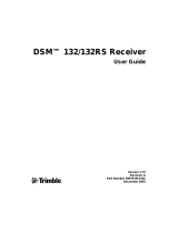
Figure 2.1 shows a front view of the SPS882 Smart GPS antenna. The front panel
contains the three indicator LEDs and the power button.
Figure 2.1 Front panel
The power button controls the receiver’s power on or off functions.
Satellite LED
Radio LED
Power LED
Power button

2 Features and Functions
16 SPS882 Smart GPS Antenna User Guide
The indicator LEDs show the status of power, satellite tracking, and radio reception.
For more information, see LED behavior, page 18.
Lower housing
Figure 2.2 shows the lower housing of the SPS882 Smart GPS antenna. The housing
contains the two serial ports, one TNC radio antenna connector, the removable battery
compartment and the 5/8-11 threaded insert.
Figure 2.2 Lower housing
Each port or connector on the Smart GPS antenna is marked with an icon to indicate
its main function, as shown in Table 2.1.
Table 2.1 Receiver ports
Icon Name Connections
Port 1 Device, computer, external radio, power in
Port 1
Port 2
TNC radio
connection
Receiver identification
antenna
5/8-11"
threaded
insert
Radio door

SPS882 Smart GPS Antenna User Guide 17
Features and Functions 2
Port 1 is a 7-pin 0-shell Lemo connector that supports RS-232 communications and
external power input. Port 1 has no power outputs.
Port 2 is a DB-9 male connector that allows for full 9-pin RS-232 communications.
Port 2 does not support power in or out. For more information on default port settings,
see Default receiver settings, page 60.
The TNC port connector is for connecting a radio antenna to the receiver internal
radio. A whip “rubber duck” antenna is supplied with the system for units with internal
UHF or 900 MHz radios. This connector is not used if you are using an external radio
receiver. For longer range operation (to provide higher gain and to raise the antenna
higher above the ground), you can use a cable to connect an external radio antenna to
the TNC port. For more information on connecting the Smart GPS antenna, see the
Chapter 5, Setting up the Receiver.
Button functions
The receiver has only one button, the Power button, represented in this manual by .
Press to switch the receiver on or off, and to perform other functions, as described
as follows:
Note – The term “press” means to press the button and release it immediately. The term
“hold” means to press the button and hold it down for the given time.
Port 2 Device, computer, external radio
RADIO Radio communications antenna
Action Power button
Turn on the receiver Press
Turn off the receiver Hold for 2 seconds
Delete the ephemeris file Hold for 15 seconds
Reset the receiver to factory defaults Hold for 15 seconds
Delete application files Hold for 30 seconds
Table 2.1 Receiver ports
Icon Name Connections

2 Features and Functions
18 SPS882 Smart GPS Antenna User Guide
LED behavior
The three LEDs on the front panel of the receiver indicate various operating
conditions. Generally, a lit or slowly flashing LED indicates normal operation, a LED
that is flashing quickly indicates a condition that may require attention, and an unlit
LED indicates that no operation is occurring. The following table defines each possible
LED state:
LED flash patterns
The following table details the possible flash patterns to indicate various states of
receiver operation.
Note – If a column shows “N/A”, that specific LED may or may not be on, but it is not
relevant to that particular mode.
The term … means that the LED …
Slow flash alternates on/off for 500 milliseconds.
Fast flash alternates rapidly on/off for 100 milliseconds
On is lit steady
Off is unlit
Receiver mode Power LED
Green
Radio LED
Green
Satellite LED
Amber
Receiver OFF OFF OFF OFF
Receiver ON
Healthy power ON N/A N/A
Low power Fast flash N/A N/A
Tracking <4 SVs ON N/A Fast flash
Tracking >4 SVs ON N/A Slow flash
Logging data internally Flashes off every
3 seconds
N/A N/A
Receiving valid data packets ON Slow flash N/A
No data packets ON OFF N/A
Monitor mode ON Slow flash ON
/