Page is loading ...

AS1000
Stepper motor
Operating instructions | EN
2019/04/09 | Version: 3.7


Documented motors
Stepper motor 3Version: 3.7
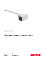
1 Documented motors
AS10xx-xxxx Standstill
torque [Nm]
Rated current
[A]
Rotor moment
of inertia [kg
cm²]
Resolution
[Steps]
Weight [kg]
AS1010-0000 0,38 1,0 0,056
1,8° / 200 Steps
0,31
AS1020-0xxx 0,5 1,0 0,074 0,39
AS1030-0000 0,6 1,5 0,21 0,68
AS1050-0xxx 1,2 5,0 0,36 1,00
AS1060-xxxx 5,0 5,0 3,0 2,85

Table of contents
Stepper motor4 Version: 3.7
Table of contents
1 Documented motors..................................................................................................................................3
2 Foreword ....................................................................................................................................................7
2.1 Notes on the documentation..............................................................................................................7
2.2 Documentation Issue Status..............................................................................................................8
2.3 Appropriate use .................................................................................................................................9
3 Guidelines and Standards ......................................................................................................................10
3.1 EC Declaration of Conformity ..........................................................................................................10
4 Safety........................................................................................................................................................11
4.1 Personnel qualification ....................................................................................................................11
4.2 Description of safety symbols..........................................................................................................11
4.3 Special safety instructions for AS1000 ............................................................................................12
5 Handling ...................................................................................................................................................13
5.1 Transport .........................................................................................................................................13
5.2 Packaging........................................................................................................................................13
5.3 Storage ............................................................................................................................................13
5.4 Maintenance / Cleaning...................................................................................................................14
5.5 Disposal...........................................................................................................................................14
6 Product identification..............................................................................................................................15
6.1 AS1000 supply schedule .................................................................................................................15
6.2 AS1000 name plate .........................................................................................................................15
6.3 AS1000 type key .............................................................................................................................16
7 Technical description..............................................................................................................................17
7.1 Design of the motors .......................................................................................................................17
7.2 General technical data.....................................................................................................................18
7.3 Standard features ............................................................................................................................18
7.3.1 Style................................................................................................................................. 18
7.3.2 Shaft end, A-side ............................................................................................................. 19
7.3.3 Flange.............................................................................................................................. 19
7.3.4 Connection technology .................................................................................................... 19
7.3.5 Feedback system............................................................................................................. 19
7.4 Options ............................................................................................................................................19
7.5 Transport, assembly and disassembly ............................................................................................19
8 Mechanical installation ...........................................................................................................................20
8.1 Important notes................................................................................................................................20
8.2 Installing the stepper motor .............................................................................................................21
8.3 Installing the incremental encoder (type 2420)................................................................................21
8.3.1 Technical data of the encoder ......................................................................................... 21
8.4 Planetary gear .................................................................................................................................22
8.4.1 Technical data of the planetary gear units....................................................................... 22
8.4.2 Installing the planetary gear............................................................................................. 22
9 Electrical installation...............................................................................................................................23
9.1 Important notes................................................................................................................................23

Table of contents
Stepper motor 5Version: 3.7
9.2 Connection of motors with preassembled cables ............................................................................24
9.3 Electrical components .....................................................................................................................25
9.3.1 Motor connector............................................................................................................... 25
9.3.2 Encoder connector........................................................................................................... 25
9.4 Connection diagram KL2531 ...........................................................................................................26
9.5 Connection diagram KL2541 ...........................................................................................................27
9.6 Connection diagram EL7031 ...........................................................................................................28
9.7 Connection diagram EL7041 ...........................................................................................................29
9.8 Connection diagram EL7037 ...........................................................................................................30
9.9 Connection diagram EL7047 ...........................................................................................................31
9.10 Connection diagram EP7041-3002 .................................................................................................32
10 Commissioning........................................................................................................................................33
10.1 Important notes................................................................................................................................33
10.2 Guide for commissioning .................................................................................................................33
10.3 Troubleshooting...............................................................................................................................34
11 Technical data..........................................................................................................................................35
11.1 Step mode and limit speeds ............................................................................................................35
11.2 AS1010-0000...................................................................................................................................36
11.2.1 Characteristic curve diagram for AS1010-0000............................................................... 37
11.2.2 Dimensional drawing AS1010-0000 ................................................................................ 38
11.3 AS1020-0xxx ...................................................................................................................................39
11.3.1 Characteristic curve diagram for AS1020-0xxx ............................................................... 40
11.3.2 Dimensional drawing AS1020-0xxx ................................................................................. 41
11.4 AS1030-0000...................................................................................................................................42
11.4.1 Characteristic curve diagram for AS1030-0000............................................................... 43
11.4.2 Dimensional drawing AS1030-0000 ................................................................................ 44
11.5 AS1050-0xxx ...................................................................................................................................45
11.5.1 Characteristic curve diagram for AS1050-0xxx ............................................................... 46
11.5.2 Dimensional drawing AS1050-0xxx ................................................................................. 47
11.6 AS1060-xxxx ...................................................................................................................................48
11.6.1 Characteristic curve diagram for AS1060-xxxx................................................................ 49
11.6.2 Dimensional drawing AS1060-0xxx ................................................................................ 50
11.6.3 Dimensional drawing AS1060-1xxx ................................................................................. 51
12 Appendix ..................................................................................................................................................52
12.1 Support and Service ........................................................................................................................52

Table of contents
Stepper motor6 Version: 3.7

Foreword
Stepper motor 7Version: 3.7
2 Foreword
2.1 Notes on the documentation
This description is only intended for the use of trained specialists in control and automation engineering who
are familiar with the applicable national standards.
It is essential that the documentation and the following notes and explanations are followed when installing
and commissioning the components.
It is the duty of the technical personnel to use the documentation published at the respective time of each
installation and commissioning.
The responsible staff must ensure that the application or use of the products described satisfy all the
requirements for safety, including all the relevant laws, regulations, guidelines and standards.
Disclaimer
The documentation has been prepared with care. The products described are, however, constantly under
development.
We reserve the right to revise and change the documentation at any time and without prior announcement.
No claims for the modification of products that have already been supplied may be made on the basis of the
data, diagrams and descriptions in this documentation.
Trademarks
Beckhoff
®
, TwinCAT
®
, EtherCAT
®
, EtherCAT G
®
, EtherCAT G10
®
, EtherCAT P
®
, Safety over EtherCAT
®
,
TwinSAFE
®
, XFC
®
, und XTS
®
and XPlanar
®
, are registered trademarks of and licensed by Beckhoff
Automation GmbH.
Other designations used in this publication may be trademarks whose use by third parties for their own
purposes could violate the rights of the owners.
Patent Pending
The EtherCAT Technology is covered, including but not limited to the following patent applications and
patents:
EP1590927, EP1789857, EP1456722, EP2137893, DE102015105702
with corresponding applications or registrations in various other countries.
EtherCAT
®
is registered trademark and patented technology, licensed by Beckhoff Automation GmbH,
Germany
Copyright
© Beckhoff Automation GmbH & Co. KG, Germany.
The reproduction, distribution and utilization of this document as well as the communication of its contents to
others without express authorization are prohibited.
Offenders will be held liable for the payment of damages. All rights reserved in the event of the grant of a
patent, utility model or design.

Foreword
Stepper motor8 Version: 3.7
2.2 Documentation Issue Status
Origin of the document
This documentation was originally written in German. All other languages are derived from the German
original.
Product features
Only the product features specified in the current user documentation are valid. Further information given on
the product pages of the Beckhoff homepage, in emails or in other publications is not authoritative.
Issue Comment
3.7 Chapter update:
Documentation Issue Status; EC Declaration of conformity; Safety; Planetary gear; Motor
connector; Encoder connector; Connection diagrams
3.6 Chapter update:
EC Declaration of conformity; Disposal 4.5
3.5 Chapter update:
Connection diagram AS1xxx 9.4 – 9.10
3.4 Chapter update:
Technical data AS1010 – AS1060 11.2 – 11.6
3.3 Chapter update:
Foreword 1.0 and Safety 3.0; 2.0
3.2 Chapter update:
7.3.1; 10.1
3.1 New chapter:
Documented motors
Chapter update:
7.4; 8.3.1; 8.4; 8.5; 8.6; 8.7; 8.8; 8.9; 10.2; 10.3; 10.4; 10.5; 10.6
3.0 General revision
2.2 Chapter revision:
• Product description – Dimensions
• Installation and operation - Installation
2.1 Chapter revision:
• Product description – Technical data

Foreword
Stepper motor 9Version: 3.7
2.3 Appropriate use
Stepper motors of the AS1000 series are mainly intended as actuators for handling equipment, textile
machines, machine tools, packaging machines and similar machines. The motors of the AS1000 series are
exclusively intended for operation based on speed and / or position control via stepper motor output stages
from Beckhoff Automation GmbH & Co. KG.
CAUTION
Danger for persons, the environment or equipment
The motors are operated in the drive system in conjunction with Beckhoff stepper motor output stages.
Please observe the entire documentation which consists of:
• AS1000 documentation (this manual)
• Complete documentation (online and paper) for Beckhoff stepper motor output stages available at
www.beckhoff.com.
• Complete machine documentation (provided by the machine manufacturer)
WARNING
Caution - Risk of injury!
Electronic equipment is not fail-safe. The machine manufacturer is responsible for ensuring
that the connected motors and the machine are brought into a safe state in the event of a
fault in the drive system.
Special safety instructions for AS1000!
For the installation and commissioning of the components the observance of the general and spe-
cial safety instructions [}12] and explanations is essential. Carefully read the chapters carefully.
The stepper motors from the AS1000 series are designed for installation as components in electrical
systems or machines and may be operated only as integrated system or machine components.
The motors may only be operated under the ambient conditions defined in this documentation.

Guidelines and Standards
Stepper motor10 Version: 3.7
3 Guidelines and Standards
CAUTION
Danger for persons, the environment or equipment
Stepper motors of the AS1000 series are not products as defined by the EC Machinery Directive. Opera-
tion of the stepper motors in machines or systems is only permitted once the machine or system manufac-
turer has provided evidence of CE conformity of the complete machine or system.
3.1 EC Declaration of Conformity
Provision of EU Declaration of Conformity:
Beckhoff Automation GmbH & Co. KG will be glad to provide you with EU declarations of conformity
and manufacturer's declarations for all products upon request to [email protected].

Safety
Stepper motor 11Version: 3.7
4 Safety
4.1 Personnel qualification
This description is only intended for trained specialists in control, automation and drive engineering who are
familiar with the applicable national standards.
4.2 Description of safety symbols
The following safety symbols and associated safety instructions are used in this document. These safety
instructions must be read and followed.
DANGER
Serious risk of injury!
Failure to follow the safety instructions associated with this symbol directly endangers the life and health of
persons.
WARNING
Caution – Risk of injury!
Failure to follow the safety instructions associated with this symbol endangers the life ans health of per-
sons.
CAUTION
Personal injuries!
Failure to follow the safety instructions associated with this symbol can be lead to injuries to persons.
NOTE
Damage to the enviroment or devices!
Failure to follow the safety instructions associated with this symbol can be lead to damage to the environ-
ment or equipment.
Tip or pointer
This symbol indicates information that contributes to better understanding.

Safety
Stepper motor12 Version: 3.7
4.3 Special safety instructions for AS1000
The safety instructions are designed to avert danger and must be followed during installation,
commissioning, production, troubleshooting, maintenance and trial or test assemblies. The stepper motors of
the AS1000 series are not designed for stand-alone operation and are always installed in a machine or
system. After installation, the documentation the documentation and the safety instructions provided by the
machine manufacturer must be read and applied.
WARNING
Serious risk of injury through hot surfaces!
• The surface temperature may exceed 100 °C, resulting in a risk of burns.
• Avoid touching the housing during or shortly after operation.
• Leave the stepper motor to cool down for at least 15 minutes after it is switched off.
• Use a thermometer to check whether the surface has cooled down sufficiently.
NOTE
Danger for persons, the environment or equipment
• Please read this manual carefully before using the stepper motor. Follow all safety instructions. If there
are sections you do not understand, please contact your sales office and refrain from working with the
stepper motor.
• Only well trained, qualified electricians with sound knowledge of drive equipment may work on the de-
vice.
• During installation, adhere to the ventilation clearances and climatic conditions. Further information can
be found in the "Technical data" and "Mechanical installation" sections.
• If a stepper motor is installed in a machine it must not be commissioned until proof of compliance of the
machine with the latest version of the EC Machinery Directive has been provided. This includes all rele-
vant harmonized standards and regulations required for implementation of this Directive in national legis-
lation.

Handling
Stepper motor 13Version: 3.7
5 Handling
5.1 Transport
• Climate category: 2K3 according to EN 60721
• Transport temperature: -25 °C - +70 °C, max. fluctuation 20 K/hour
• Transport humidity: relative humidity 5% - 95%, non-condensing
• The stepper motor may only be transported by qualified personnel and in the manufacturer's original
recyclable packaging.
• Avoid hard impacts, particularly at the shaft end.
• If the packaging is damaged, check the motor for visible damage. Inform the transport company and, if
necessary, the manufacturer.
5.2 Packaging
• Cardboard packaging
Motor without installed gear unit
Motor type Max. stacking height
AS1010 5
AS1020 5
AS1030 5
AS1050 5
AS1060 3
Motor with installed gear unit
Motor and gear type Max. stacking height
AS1030 with AG1000-PM052.00x 3
AS1050 with AG1000-PM052.00x 3
AS1060 with AG1000-PM081.00x 2
5.3 Storage
• Climate category: 2K3 according to EN 60721
• Storage temperature: -25 °C - +55 °C, max. fluctuation 20 K/hour
• Air humidity: relative humidity 5% - 95%, non-condensing
• Max. stacking height: see table Packaging
• Storage time: without limitation
• Store only in the manufacturer’s original recyclable packaging.

Handling
Stepper motor14 Version: 3.7
5.4 Maintenance / Cleaning
• Maintenance and cleaning only by qualified personnel.
• The ball bearings have a grease filling. The actual life of the bearings depends on various factors,
including the radial load, shear load, operating temperature and motor speed.
• Check the motor for bearing noise every 2,500 operating hours or once per year. If any noises are
heard, stop the operation of the motor. The bearings must be replaced.
• Opening the motor invalidates the warranty.
• Clean the housing with isopropanol or similar.
NOTE
Destruction of the stepper motor
Never immerse or spray the stepper motor.
5.5 Disposal
In accordance with the WEEE 2012/19/EU Directives we take old devices and accessories back for
professional disposal, provided the transport costs are taken over by the sender.
Send the devices with the note “For disposal” to:
Beckhoff Automation GmbH & Co. KG
Huelshorstweg 20
D-33415 Verl

Product identification
Stepper motor 15Version: 3.7
6 Product identification
6.1 AS1000 supply schedule
Please check that the delivery includes the following items:
• AM1000 series motor
• Connecting cable with 4-pin M12 connector (underside firmly connected)
• Online documentation at www.beckhoff.de
Scope of supply
The M12 mating connectors are not included!
The following accessories are available on request:
• Second shaft end for AS1020, AS1050 and AS1060
• Encoder with connection cable and 5-pin, screened M12 socket
• Preassembled motor and feedback cable
• Planetary gear, AG1000 series
6.2 AS1000 name plate

Product identification
Stepper motor16 Version: 3.7
6.3 AS1000 type key

Technical description
Stepper motor 17Version: 3.7
7 Technical description
7.1 Design of the motors
Beckhoff stepper motors of the AS1000 series are synchronous motors with a large number of poles. They
are classified as direct drives. The stepper motors of the AS1000 series are characterized by a high holding
torque and very good positioning capability. Thanks to sophisticated control of the stator windings in full-step
or micro-step mode, individual steps or partial steps can be executed directly without a feedback system.
This feature distinguishes stepper motors from servomotors, thus representing a cost-effective alternative
approach. Excessive acceleration and fast load cycles can result in the stepper motor being unable to follow
the rotating field and therefore "losing steps". The encoder option can improve matters in this situation.
The stepper motor has its highest torque in the lower speed range. At standstill, the stepper motor is
characterized by a very high holding torque. In many applications, this eliminates the need for a holding
brake. In the Beckhoff stepper motor terminals a suitable current curve can be stored for any speed or load
profile. This serves to optimally adapt the thermal load of the motor. Beckhoff stepper motors are used as
actuators or auxiliary axes in machine construction and automation applications. In conjunction with the
stepper motor output stages and the Beckhoff TwinCAT automation system, this facilitates integration of
cost-effective axes into the overall application. In order to simplify the electrical connection, the stepper
motors are equipped with pre-assembled plug connectors. Planetary gear units, incremental encoders and
pre-assembled connection cables are available as accessories.

Technical description
Stepper motor18 Version: 3.7
7.2 General technical data
Insulation class Class B (130°C) according to IEC60085
Temperature change at rated current Max. 80 K
Insulation resistance ≥ 100 MΩ
Permissible ambient temperature (operation) -10°C to +50°C
Permissible ambient temperature (transport/
storage)
-25℃ to +70℃
Permissible air humidity 20% to 90%, non-condensing
Permissible level of contamination Contamination level 2 according to EN60204/
EN50178
Corrosion protection Under extreme operating conditions, special
measures must be agreed with the manufacturer, and
implemented by the user.
Permissible operating altitude Up to 1000 m above sea level
Maximum cable length between motor and
terminal
10 m
Special operating conditions The applicability of the Beckhoff AS1000 stepper
motor is to be determined for each individual case.
Application in harsh operating or environmental
conditions requires coordination between
manufacturer and user.
Correct installation position Horizontal or vertical
Ventilation Ensure adequate ventilation of the motors.
Protection class (doesn´t apply to the shaft
bushing)
AS1010 – AS1050: IP43
AS1060: IP20
7.3 Standard features
7.3.1 Style
The design of the AS1010 and AS1020 stepper motors is intended for flange mounting based on installation
types IM B14, IM V18 and IM V19.
The design of the AS1030/AS1050 and AS1060 stepper motors is intended for flange mounting based on
installation types IM B5, IM V1 and IM V3.
The permitted mounting positions are specified in the technical data.
NOTE
Destruction of the motors
Installation positions IM V1 and IM V3 may result in liquid entering the motor and associated damage.

Technical description
Stepper motor 19Version: 3.7
7.3.2 Shaft end, A-side
The force transfer is friction-locked (backlash-free), via a clutch, via the cylindrical shaft end A, or optionally
as a form-locking connection via a feather key groove according to DIN6885.
Radial force
If the motors drive via pinions or toothed belts, then high radial forces will occur.
Axial force
Axial forces occur when assembling pinions or pulleys on the shaft.
Coupling
Double-coned collets, possibly in association with metal bellows couplings, have proven themselves as
excellent, zero backlash coupling elements.
7.3.3 Flange
Flange dimensions according to IEC standard, fit j6, accuracy according to DIN 60034-7
Tolerance class: N
7.3.4 Connection technology
The motors are equipped with connecting cables (300 mm) and M12 connectors for the power supply and
the feedback signals (encoders only).
The mating connectors are not included in the scope of supply. Ready-made extension cables in different
lengths are available as accessories.
7.3.5 Feedback system
Feedback system Resolution Comment
Incremental encoders 200 increments Only for AS1020/AS1050/
AS1060
Incremental encoders 1024 increments Only for AS1020/AS1050/
AS1060
7.4 Options
Feather key
Only the AS1060 is optionally available with groove and feather key.
7.5 Transport, assembly and disassembly
CAUTION
Personal injuries!
Protective clothing, protective gloves and safety boots must be worn at all times during transport, assembly
and disassembly. Do not step under suspended motors.
The motors of the AS1000 series can be moved without auxiliary equipment.

Mechanical installation
Stepper motor20 Version: 3.7
8 Mechanical installation
8.1 Important notes
NOTE
Destruction of the motors
• Protect the motors from unacceptable stresses. Take care, especially during transport and handling, that
components are not bent and that insulation clearances are not altered.
• The site must be free of conductive and aggressive material. For V1/V3-mounting (shaft end upwards),
make sure that no liquids can enter the bearings. If an encapsulated assembly is required, please con-
sult our applications department beforehand.
• Ensure unhindered ventilation of the motors and observe the permissible ambient and flange tempera-
tures. For ambient temperatures above 50 °C please consult our applications department beforehand.
• Stepper motors are precision devices. The flange and shaft are especially vulnerable during storage and
assembly. It is important to use the locking thread which is provided to tighten up couplings, gear wheels
or pulleys and warm up the drive components, where possible. Blows or the use of force will lead to
damage to the ball bearings, the shaft, the holding brake and the feedback system.
• Wherever possible, use only backlash-free, frictionally-locking collets or couplings. Ensure correct align-
ment of the couplings. A displacement will cause unacceptable vibration and the destruction of the ball
bearings and the coupling.
• For toothed belts, it is vital to observe the permissible radial forces. An excessive radial load on the shaft
will significantly shorten the service life of the motor.
• Avoid axial loads on the motor shaft, as far as possible. Axial loading significantly shortens the service
life of the motor and can result in malfunction of the brake.
• In any case, avoid creating a mechanically constrained motor shaft mounting by using a rigid coupling
with additional external bearings (e.g. in a gearbox).
• Check compliance with the permitted radial and axial loads F
R
and F
A
. When using a toothed belt drive,
the minimum permitted diameter of the pinion follows from the equation:
/