Page is loading ...

ENGLISH
CEILING & FLOOR TYPE AIR CONDITIONERS
INSTALLATION INSTRUCTIONS
• Please read this instruction sheet completely before installing the product.
• When the power cord is wanted to replace, replacement work shall be performed by authorized
personnel only.
• Installation work must be performed in accordance with national wiring standards by authorized
personnel only.
P/No.: 3828A20361A
(Side)
(Rear)
Air intake
vents
Air outlet
vents
Control Cover
Connecting Wire
Connection Pipe
Drain Hose
(Side)
(Rear)
Air intake vents
Air outlet vents
Piping
Drain hose
Connecting
wire
Control
cover
Air filters
Remote Controller
Indoor Unit
Outdoor Unit
ENGLISH

1.The following should be always observed for safety ...............................3
2. Installation of Indoor, Outdoor unit
3. Connecting Pipes to the Indoor Unit
4. Connecting Pipes to the Outdoor Unit
5. Checking the Drainage..............................................................................13
6. Connecting Cables between Indoor Unit and Outdoor Unit
7. Air Purging of the Connecting Pipes and the Indoor Unit ....................17
OUT-LINE OF INSTALLATION
Installation works Installation Parts Required tools
1)
Selection of the best
location
............................4
2) Indoor unit installation....5
•
Four Type “A” screws
•
Connecting cable
•
Level
•
Screw driver
•
Electric drill
•
Hole core drill (ø70mm)
1) Preparation of Piping...11
•
Pipes: Gas side .....
5
/
8
",
3
/
4
"
Liquid side .............
1
/
4
",
3
/
8
",
1
/
2
"
•
Insulated drain hose
•
Insulation materials
•
Flaring Tools set
1) Connecting the pipes to
the Outdoor Unit..........13
•
Additional Drain hose
(Inner Dia...............25mm)
1) Connecting cables to the
Indoor Unit...................14
2) Clamping of cables......14
3) Connecting cables to the
Outdoor Unit ................15
4) Form the pipings..........16
•
Screw driver
•
Hexagonal Wrench (4mm/5mm)
•
Gas-leak Detector
2

ENGLISH
3
1. The following should be always observed for safety
• Please report to or take consent by the supply authority before connecting to the system.
• Be sure to read "THE FOLLOWING SHOULD BE ALWAYS OBSERVED FOR SAFETY" before
installing the air conditioner.
• Be sure to observe the cautions specified here as they include important items related to safety.
• The indications and meanings are as follows.
• After reading this manual, be sure to keep it together with the owner's manual in an accessible
place.
Could lead to death, serious injury, etc.
Do not install it yourself (customer).
Perform the installation securely referring to the
installation manual.
Install the unit securely in a place which can bear the
weight of the unit.
Perform electrical work according to the installation
manual and be sure to use an exclusive circuit.
Attach the electrical part cover to the indoor unit and
the service panel to the outdoor unit securely.
Be sure to use the part provided or specified parts for
the installation work.
Check that the refrigerant gas do not leak after
installation is completed.
Perform the drainage/piping work securely
according to the installation manual.
Use the specified wires to connect the indoor and the
outdoor units securely and attach the wires firmly to
the terminal board connecting sections so the stress
of the wires is not applied to the sections.
• Incomplete installation could cause injury due to fire, electric shock,
the unit falling or a leakage of water. Consult the dealer from whom
you purchased the unit or special installer.
• Incomplete installation could cause a personal injury due to
fire, electric shock, the unit falling or a leakage of water.
• When installed in an insufficient strong place, the unit could fall
causing injured.
• Incomplete connecting and fixing could cause fire.
• If the capacity of the power circuit is insufficient or there is
incomplete electrical work, it could result in a fire or an electric
shock.
• The use of defective parts could cause an injury or leakage of
water due to a fire, electric shock, the unit falling, etc.
• If there is a defect in the drainage/piping work, water
could drop from the unit and household goods could be
wet and damaged.
Do not install the unit in a place where an
inflammable gas leaks.
• If gas leaks and accumulates in the area surrounding the unit, it
could cause an explosion.
• If the electrical part cover if the indoor unit and/or the service
panel if the outdoor unit are not attached securely, it could result
in a fire or electric shock due to dust, water, etc.
Could lead to serious injury in particular environments when operated incorrectly.
WARNING
WARNING
CAUTION
CAUTION

1. Selection of the best location
1) Indoor unit
• There should not be any heat source or steam
near the unit.
• There should not be any obstacles to prevent
the air circulation.
• A place where air circulation in the room will
be good.
• A place where drainage can be easily
obtained.
• A place where noise prevention is taken into
consideration.
• Do not install the unit near the door way.
• Ensure the spaces indicated by arrows from
the wall, ceiling, or other obstacles.
2) Outdoor unit
• If an awning is built over the unit to prevent
direct sunlight or rain exposure, be careful
that heat radiation from the condenser is not
restricted.
• There should not be any animals or plants
which could be affected by hot air
discharged.
• Ensure the spaces indicated by arrows from
the wall, ceiling, fence or other obstacles.
3) Piping length and the elevation
4
Indoor unit
Outdoor unit
B
A
More than
30cm
More than
30cm
More than
70cm
Sunroof
Fence or
obstacles
300
mm
300
mm
300
mm
300
mm
100mm
or more
300mm
or more
Service space when the unit is mounted
under the celling.
Service space when the unit is mounted
on the floor/wall.
2. Installation of Indoor, Outdoor Unit
• If 36K Model is installed at a distance of 15m, 225g of
refrigerant should be added (15-7.5) x 30g = 225g
• Capacity is based on standard length and maximun allowance
length is on the basis of reliability.
• Improper refrigerant charge may result in abnormal cycle.
36K BTU/h
42K BTU/h
48K BTU/h
60K BTU/h
30
35
40
45
Capacity
Gas
5/8"
3/4"
3/4"
3/4"
Liquid
3/8"
3/8"
1/2"
1/2"
Elevation B(m)
Length A(m)
*Additional
refrigerant
(g/m)
Pipe Size
(Diameter: Ø)
Standard
7.5
7.5
7.5
7.5
Standard
5
5
5
5
Max.
15
15
15
15
Max.
10
10
10
10

ENGLISH
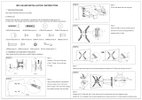
2. Indoor unit installation
■ Installation of Unit
Unit should be installed for horizontal
and vertical discharge application only.
• Apply a joint-canvas between the unit and
duct to absorb unnecessary vibration.
• Install the unit leaning to a drainage hole
side as a figure for easy water drainage.
• A place where the unit will be leveled and
that can support the weight of the unit.
• A place where the unit can withstand its
vibration.
• A place where service can be easily
performed.
5
CASE 1
POSITION OF SUSPENSION BOLT
CASE 2
POSITION OF CONSOLE BOLT
(Unit:mm)
90
400
94
23
94
A
650
400 90
B
C
11
Suspension
bolts
Spring
washer
Max.
12mm
Washer
Nut
ABC
Dimension
Capacity
36K BTU/h 1550 1362 236
42K BTU/h 1550 1362 236
48K BTU/h 1550 1362 272
60K BTU/h 1550 1362 272

6
• Select and mark the position for fixing
bolts.
• Drill the hole for set anchor on the face
of ceiling.
• Insert the set anchor and washer onto
the suspension bolts for locking the
suspension bolts on the ceiling.
• Mount the suspension bolts to the set
anchor firmly.
• Secure the installation plates onto the
suspension bolts (adjust level roughly)
using nuts, washers and spring
washers.
Opening the side panel method
Step1: Remove screw
Step2: Lift side-panel upward slightly
Step3: To move side panel along arrow as
shown.
1 Set anchor
Old building
Step1
Step2 Step3
New building
2 Plate washer
3 Spring washer
4 Nut
5 Suspension
bolts
Tighten the nut and bolt to prevent
unit falling
CAUTION
• Local supply
Set anchor
Plate washer - M10
Spring washer - M10
Nut - W3/8 or M10
Suspension bolt - W3/8 or M10

ENGLISH
Drain hose
Ceiling
CAUTION
Ceiling
7
1. Install declination of the indoor unit is very important for the drain of the convertible
type air conditioner.
2. Minimum thickness of the insulation for the connecting pipe shall be 7mm.
3. If the Installation Plates are fixed to horizontal line, the indoor unit after installing will be
declined to the bottomside.
Front of view
• The unit must be horizontal or declined to the drain hose connected when finished
installation.
• The unit must be declined to the bottomside of the unit when finished installation.
Side of view

8
• Drill the piping hole with 70mm dia, hole
core drill.
• Piping hole should be slightly slant to the
outdoor side.
INSULATION, OTHERS
Insulate the joint and tubes completely.
All thermal insulation must comply with local requirement.
REFRIGERANT PIPE
• Insulate and tape both the gas piping and
liquid piping.
■ After all workings are finished, check the working and operation.
• Air distribution Is the air circulation good?
• Drain Is the drainage smoothly and no sweating?
• Gas leakage Is the piping connection correctly?
• Wiring Is the wiring connection correctly?
• Lock-bolt Is the lock-bolt of compressor loosened?
THERMAL INSULATION
TEST AND CHECK
5~7mm
Indoor Outdoor
WALL
Power cable
Liquid pipe
Thermal insulator
Gas pipe
Tape

ENGLISH
9
Flared connection (Union)
Flared connection
(Service valve, Ball valve)
Use a seemliness tube
Factory charged
Indoor
Outdoor
REFRIGERANT PIPING
INSTALLATION OF OUT DOOR UNIT
Perform the work according to the Service
Manual or Installation Guide.
Select a location that satisfies the following
conditions. Install the unit firmly in place.
■ Select the following location
• A place where the air conditioner can
get good ventilation.
• A place where it shall not annoy the
neighbors.
• A place where the unit shall be leveled
and that can support the weight of unit
and withstand its vibrations.
■ Keep a maintenance space
• Use two spanners when connecting the
refrigerant pipe to the unit.
• Make a bend with a radius as large as
possible.
• Perform air purge with R-22 or vacuum
drying.
• When piping work is finished, check all
joints.
■ Add refrigerant if piping is over 7.5m.
Above 70Cm
Above 30Cm
Outdoor unit
Above 30Cm Above 50Cm
Face of wall
Capacity Addition volume
36K BTU/h 30 g/m
42K BTU/h 35 g/m
48K BTU/h 40 g/m
60K BTU/h 45 g/m

Outdoor
Indoor
Main
power source
Switch box
Circuit Breaker
Main terminal board
Control terminal board
Cord
clamper
Cover control
Control terminal board
Cord damper
ELECTRICAL WIRING
INDOOR UNIT
• Remove side panel cover for electrical
connection between the indoor and
outdoor unit.
(Remove crews ➀.)
• Use the cord clamper to fix the cord.
Perform the electrical wiring work according to
the electrical wiring connection.
• All wiring must comply with local
requirements.
• Select a power source that is capable of
supplying the current required by the air
conditioner.
•
Use a recognized circuit breaker
between the power source and the unit.
A disconnection device to adequately
disconnect all supply lines must be fitted.
• Capacity of circuit breaker
WIRING CONNECTION
OUTDOOR UNIT
• Remove the control cover for wiring
connection.
• Use the cord clamper to fix the cord.
• Earthing work
Connect the cable of diameter 1.6mm
2
or more to the earthing terminal
provided in the control box and do
earthing.
Please check !!
10
Capacity 1 Phase 3 Phase
36K BTU/h 35A -
42K BTU/h 40A -
48K BTU/h 50A -
60K BTU/h 50A -

ENGLISH
11
3-1. Preparation of Piping
3. Connecting Pipes to the Indoor Unit
Main cause of gas leakage is defect in
flaring work. Carry out correct flaring work
in the following procedure.
1) Cut the pipes and the cable.
■ Use the accessory piping kit or the pipes
purchased locally.
■ Measure the distance between the
indoor and the outdoor unit.
■ Cut the pipes a little longer than
measured distance.
■ Cut the cable 1.5m longer than the pipe
length.
2) Burrs removal
■ Completely remove all burrs from the cut
cross section of pipe/tube.
■ Put the end of the copper tube/pipe to
downward direction as you remove burrs
in order to avoid to let burrs drop in the
tubing.
3) Putting nut on
■ Remove flare nuts attached to indoor
and outdoor units, than put them on
pipe/tube having completed burr
removal.
(Not possible to put them on after flaring
work)
4) Flaring work
■ Carry out flaring work using flaring tool
as shown below.
Firmly hold copper tube in a bar(or die) as
indicated dimension in the table above.
5) Check
■ Compare the flared work with figure.
■ If flare is noted to be defective, cut off
the flared section and do flaring work
again.
Copper
tube
90°
Slanted Uneven Rough
Pipe
Reamer
Point down
Flare nut
Copper tube
Bar
Copper pipe
Clamp handle
Red arrow mark
Cone
Yoke
Handle
Bar
"A"
Inclined
Inside is shining without scratches.
Smooth all round
Even length
all round
Surface
damaged
Cracked Uneven
thickness
= Improper flaring =
Outside Diameter "A"
1/4" 0~0.5
3/8" 0.5~0.8
1/2" 0.5~0.8
5/8" 0.8~1.0
3/4" 1.0~1.3

6) Pipe bending
Annealed copper pipe with small diameter (ø6.35 or ø9.52) can be easily bent manually. In
this case, secure large R(radius) for the bend section and gradually bend pipe. If annealed
copper pipe is large in diameter (ø15.88 or ø19.05), bend pipe with bender. Use bender
appropriate for the pipe diameter.
7)
Brazing
In refrigerant piping, bending (in particular, acute bending) must be minimized to reduce
piping resistance. Bending is, however, necessary in some places by virtue of the installation
position of devices auxiliary to the packaged air conditioner, or of the building structure,
piping distance or finishing appearance. If a more acute bend is required than that attainable
by pipe bender, perform brazing using ready-made elbow. Aside from this function, brazing
also serves to connect straight pipes, generally using ready-made sockets. While brazing,
protect piping against heat with wet cloth to avoid damaging valve packing or burning
thermal insulator with burner heat. While brazing, blow inert gas (nitrogen gas or carbonic
gas) to prevent formation of oxidation film in copper piping; otherwise, the refrigerant circuit
will clog. The blowing of nitrogen gas (or carbonic gas) through 3-way valves is described in
the following:
8)
Refrigerant piping(Flare piping)
When connecting piping, be sure to keep piping dry(keep piping away from water), clean
(keep piping away from dust) and airtight (avoid refrigerant leakage).
When connecting piping on rainy days or making a through-hole in wall, take due care to
prevent water or plaster from entering piping.
CAUTION
a. This procedure is designed to prevent
formation of oxidation film by filling piping
with inert gas. Note that excessive gas
pressure will generate pinholes at brazed
points.
(Nitrogen gas: Supply pressure
0.05~0.1kg/cm
2
G)
b. When supplying inert gas, be sure to open
one end of piping.
Water enters Plaster enters
12

ENGLISH
13
1) Connecting the pipes to the
Outdoor unit
1. Align the center of the pipings and
sufficiently tighten the flare nut with
fingers.
2. Finally, tighten the flare nut with torque
wrench until the wrench clicks.
• When tightening the flare nut with torque
wrench, ensure the direction for
tightening follows the arrow on the
wrench.
1) Checking the Drainage
1. Remove the Air Filter.
• To remove air filter, take hold of tab and
pull slightly upwards.
2. Check the drainage.
• Spray one or two glasses of water upon
the evaporator.
• Ensure that water flows drain hose of
indoor unit without any leakage.
4. Connecting Pipes to the Outdoor Unit
5. Checking the Drainage
Torque wrench
Outdoor unit
Gas side piping
(Bigger Dia.)
Liquid side piping
(Smaller Dia.)
Pipe size Torque
1/4" 1.8kg.m
3/8" 4.2kg.m
1/2" 5.5kg.m
5/8" 6.6kg.m
3/4" 6.6kg.m

1) Connecting cables to the Indoor Unit
■ Connect the wires to the terminals on the control board individually according to the outdoor
unit connection.
• Ensure that the color of the wires of outdoor unit and the terminal No. are the same as those
of indoor unit respectively
The power cord connected to the outdoor unit should be
complied with the following specifications (Rubber
insulation, type H05RN-F approved by HAR or SAA).
If the supply cord is damaged, it must be replaced by a special cord or assembly availible from the manufacturer of its service agent.
The connecting cable connected to the indoor and outdoor
unit should be complied with the following specifications
(Rubber insulation, type H05RN-F approved by HAR or SAA).
CAUTION
20mm
GN/YL
NORMAL
CROSS-SECTIONAL
AREA 0.75mm
2
(36K/42K)
1.25mm
2
(48K)
20mm
GN/YL
Capacity
36K BTU/h
42K BTU/h
48K BTU/h
60K BTU/h
1 Phase
5.5mm
2
8.5mm
2
8.5mm
2
8.5mm
2
NORMAL CROSS-SECTIONAL AREA
• Cooling only type
Terminals on the indoor unit
1(N) 2(L)
345
1(N) 2(L)
345
Terminals on the outdoor unit
POWER INPUT
(220V)
1(L) 2(N)
■ 36K/42K/48K/60K Btu
6. Connecting Cables between Indoor Unit and Outdoor Unit
14

ENGLISH
15
3) Connecting the cable to the
Outdoor Unit
1. Remove the Cover control from the unit
by loosening a screw.
Connect the wires to the terminals on
the control board individually as
following.
2. Secure the cable onto the control board
with the holder (clamper).
3. Refix the cover control to the original
position with the screw.
CAUTION
After the confirmation of the above conditions, prepare the wiring as follows:
1) Never fail to have an individual power specialized for the air conditioner. As for the method
of wiring, be guided by the circuit diagram pasted on the inside of control box cover.
2) Provide a circuit breaker switch between power source and the unit.
3) The screw which fasten the wiring in the casing of electrical fittings are liable to come
loose from vibrations to which the unit is subjected during the course of transportation.
Check them and make sure that they are all tightly fastened. (If they are loose, it could give
rise to burn-out of the wires.)
4) Specification of power source
5) Confirm that electrical capacity is sufficient.
6) Be sure that the starting voltage is maintained at more than 90 percent of the rated voltage
marked on the name plate.
7) Confirm that the cable thickness is as specified in the power sources specification.
(Particularly note the relation between cable length and thickness.)
8) Never fail to equip a leakage breaker where it is wet or moist.
9) The following troubles would be caused by voltage drop-down.
• Vibration of a magnetic switch, damage on the contact point there of, fuse breaking,
disturbance to the normal function of a overload protection device.
• Proper starting power is not given to the compressor.
Terminal block
Cord Clamper
Cover control
Power supply
cord
Outdoor unit
Over 5mm

4) Form the pipings
1. Wrap the connecting portion of indoor
unit with the Insulation material and
secure it with two Plastic Bands. (for the
right pipings)
• If you want to connect an additional drain
hose, the end of the drain-outlet should
keep distance from the ground. (Do not
dip it into water, and fix it on the wall to
avoid swinging in the wind.)
2. Tape the Pipings, drain hose and
Connecting Cable from bottom to top.
3. Form the pipings gathered by taping
along the exterior wall and fix it onto the
wall by saddle or equivalent.
2. Tape the Pipings and Connecting cable
from bottom to top.
3. Form the pipings gathered by taping
along the exterior wall, and make the
trap prevent water from entering into the
room.
4. Fix the pipings onto the wall by saddle
or equivalent.
In case of the Outdoor unit being installed
below position of the Indoor unit.
In case of the Outdoor Unit being installed
above position of the Indoor Unit.
Trap is required to prevent water from entering
into electrical parts.
Seal a small opening
around the pipings
with gum type sealer.
Drain hose
Taping
Pipings
Connecting
cable
Power supply
cord
Seal a small opening
around the pipings
with gum type sealer.
Trap
16

ENGLISH
17
7. Air Purging of the Connecting Pipes and the Indoor Unit
Indoor unit
Outdoor unit
Liquid side
CLOSEOPEN
Vaccum pump
Gas side
Closed
Closed
2-way valve/
3-way valve
3-way
valve
The air which contains moisture remaining in the refrigeration cycle may cause a malfunction
on the compressor.
1. Confirm that both the liquid side valve and the gas side valve are set to the closed position.
2. After connecting the piping, check the joints for gas leakage with gas leak detector.
3. Remove the service port nut, and connect the gauge manifold and the vacuum pump to the
service port by the charge hose.
4. Vacuum the indoor unit and the connecting pipes until the pressure in them lowers to below -
76cmHg.
5. Remove the valve stem nuts, and fully open the stems of the 2-way and 3-way valves with a
hexagon wrench.
6. Tighten the valve stem nuts of the 2-way valve and 3-way valve.
7. Disconnect the charge hose and fit the nut to the service port.
(Tightening torque: 1.8kg.m)

Memo
18

Memo
19
ENGLISH
/