Page is loading ...

Ceiling And Floor Type
INSTALLATION MANUAL
Thank you very much for purchasing our air conditioner,
Before using your air conditioner , please read this manual carefully and keep it for future reference.
KUIR - KFUF Series

1
installation manual
1. PRECAUTIO
The safty precautions listed here are divided into two categories.
After completing the installation, make sure that the unit operates
properly during the start-up operation. Please instruct the customer
on how to operate the unit and keep it maintained.Also, inform
customers that they should store this installation manual along with
the owner's manual for future reference.
Be sure only trained and qualified service personnel to
install, repair or service the equipment.
Improper installation, repair, and maintenance may result in
electric shocks, short-circuit, leaks, fire or other damage to
the equipment.
CONTENTS PAGE
PRECAUTIONS.......................................................................................1
INSTALLATION INFORMATION................................................................2
ATTACHED FITTINGS..............................................................................3
INSPECTING AND HANDLING THE UNIT.................................................4
INDOOR UNIT INSTALLATION.................................................................4
OUTDOOR UNIT INSTALLATION..............................................................6
CONNECT THE DRAIN PIPE.....................................................................8
INSTALL THE CONNECTING PIPE............................................................9
AIR EVACUATION..................................................................................12
WIRING.................................................................................................13
TEST OPERATION..................................................................................13
Install according to this installation instructions strictly.
If installation is defective, it will cause water leakage,
electrical shock and fire.
When installing the unit in a small room, take measures
against to keep refrigerant concentration from exceeding
allowable safety limits in the event of refrigerant leakage.
Contact the place of purchase for more information.
Excessive refrigerant in a closed ambient can lead to oxygen
deficiency.
Use the attached accessories parts and specified parts
for installation.
otherwise, it will cause the set to fall, water leakage,
electrical shock and fire.
Install at a strong and firm location which is able to
withstand the set' s weight.
If the strength is not enough or installation is not properly
done, the set will drop to cause injury.
The appliance shall not be installed in the laundry.
Before obtaining access to terminals, all supply circuits
must be disconnected.
The appliance must be positioned so that the plug is
accessible.
The enclosure of the appliance shall be marked by word,
or by symbols, with the direction of the fluid flow.
For electrical work, follow the local national wiring
standard, regulation and this installation instructions. An
independent circuit and single outlet must be used.
If electrical circuit capacity is not enough or defect in
electrical work, it will cause electrical shock fire.
Use the specified cable and connect tightly and clamp
the cable so that no external force will be acted on the
terminal.
If connection or fixing is not perfect, it will cause heat-up or
fire at the connection.
Wiring routing must be properly arranged so that control
board cover is fixed properly.
If control board cover is not fixed perfectly, it will cause
heat-up at connection point of terminal, fire or electrical
shock.
If the supply cord is damaged, it must be replaced by the
manufacturer or its service agent or a similarly qualified
person in order to avoid a hazard.
An all-pole disconnection switch having a contact
separation of at least 3mm in all poles should be
connected in fixed wiring.
When carrying out piping connection, take care not to let
air substances go into refrigeration cycle.
Otherwise, it will cause lower capacity, abnormal high
pressure in the refrigeration cycle, explosion and injury.
Do not modify the length of the power supply cord or use
of extension cord, and do not share the single outlet with
other electrical appliances.
Otherwise, it will cause fire or electrical shock.
Carry out the specified installation work after taking into
account strong winds, typhoons or earthquakes.
Improper installation work may result in the equipment falling
and causing accidents.
CAUTION
WARNING
WARNING
If you do not follow these instrutions exactly, the unit may
cause property damage, personal injury or loss of life.
If you do not follow these instrutions exactly, the unit may
cause minor or moderate property damage, personal
injury.
keep this manual where the operator can easily find them.
Read this manual attentively before starting up the units.
For safety reason the operator must read the following
cautions carefully.
Installation must be performed in accordance with the
requirement of NEC and CEC by authorized personnel only.
(Applicable to the North American area only)

2
installation manual
To install properly, please read this "installation manual" at
first.
The air conditioner must be installed by qualified persons.
When installing the indoor unit or its tubing, please follow
this manual as strictly as possible.
If the air conditioner is installed on a metal part of the
building, it must be electrically insulated according to the
relevant standards to electrical appliances.
When all the installation work is finished, please turn on
the power only after a thorough check.
Regret for no further announcement if there is any change
of this manual caused by product improvement.
2. INSTALLATION INFORMATION
Ground the air conditioner.
Do not connect the ground wire to gas or water pipes,
lightning rod or a telephone ground wire.Inappropriate
grounding may result in electric shocks.
Be sure to install an earth leakage breaker.
Failure to install an earth leakage breaker may result in
electric shocks.
Connect the outdoor unit wires , then connect the indoor
unit wires.
You are not allowed to connect the air conditioner with the
power supply until the wiring and piping is done.
While following the instructions in this installation
manual, install drain piping in order to ensure proper
drainage and insulate piping in order to prevent
condensation.
Improper drain piping may result in water leakage and
property damage.
Install the indoor and outdoor units, power supply wiring
and connecting wires should be at least 1 meter away
from televisions or radios in order to prevent image
interference or noise.
Depending on the radio waves, a distance of 1 meter may not
be sufficient enough to eliminate the noise.
The appliance is not intended for use by young children
or infirm persons without supervision.
Don't install the air conditioner in the following
circumstance:
There is petrolatum existing.
There is salty air surrounding (near the coast).
There is caustic gas (the sulfide, for example) existing
in the air (near a hot spring).
The Volt vibrates violently (in the factories).
In buses or cabinets.
In kitchen where it is full of oil gas.
There is strong electromagnetic wave existing.
There are inflammable materials or gas.
There is acid or alkaline liquid evaporating.
Other special conditions.
If the refrigerant leaks during installation, ventilate the
area immediately.
Toxic gas may be produced if the refrigerant comes into the
place contacting with fire.
The temperature of refrigerant circuit will be high, please
keep the interconnection cable away from the copper
tube.
After completing the installation work, check that the
refrigerant does not leak.
Toxic gas may be produced if the refrigerant leaks into the
room and comes into contact with a source of fire, such as a
fan heater, stove or cooker.
INSTALLATION ORDER
Select the location;
Install the indoor unit;
Install the outdoor unit;
Install the connecting pipe ;
Connect the drain pipe;
Wiring;
Test operation.
CAUTION
The appliance shall be installed in accordance with
national wiring regulations.
Do not operate your air conditioner in a wet room such
as a bathroom or laundry room.
An all-pole disconnection device which has at least 3mm
clearances in all poles , and have a leakage current that
may exceed 10mA, the residual current device (RCD)
having a rated residual operating current not exceeding
30mA, and disconnection must be incorporated in the
fixed wiring in accordance with the wiring rules.

3
installation manual
3. ATTACHED FITTINGS
Please check whether the following fittings are of full scope. If there are some spare fittings , please restore them carefully.
QUANTITY SHAPE NAME
5. Owner's manual
6. Installation manual
7. Remote controller manual
1. Remote controller
(on some models)
2. Remote controller holder
(on some models)
4. Alkaline dry batteries (AM4)
1
1
2
2
1
1
Remote controller & Its Holder
Others
3. Mounting screw(ST2.9×
10-C-H)
1

4
installation manual
Keep indoor unit, outdoor unit, power supply wiring and
transmission wiring at least 1 meter away from televisions
and radios. This is to prevent image interference and
noise in those electrical appliances. (Noise may be
generated depending on the conditions under which the
electric wave is generated, even if 1 meter is kept.)
5.2 Install the main body
There is enough room for installation and maintenance.
The ceiling is horizontal, and its structure can endure the
weight of the indoor unit.
The outlet and the inlet are not impeded, and the
influence of external air is the least.
The air flow can reach throughout the room.
The connecting pipe and drainpipe could be extracted out
easily.
There is no direct radiation from heaters.
5. INDOOR UNIT INSTALLATION
5.1 Installation place
(Refer to Fig.5-1,Fig.5-2 and Table 5-1 for specification.)
The indoor unit should be installed in a location that meets
the following requirements:
4. INSPECTING AND HANDLING THE UNIT
At delivery, the package should be checked and any damage should
be reported immediately to the the service agent.
When handling the unit, take into account the following:
Fragile, handle the unit with care.
Keep the unit upright in order to avoid compressor
damage.
Choose on before hand the path along which the unit is to be
brought in.
Move this unit as originally package as possible.
When lifting the unit , always use protectors to prevent belt
damage and pay attention to the position of the unit’s centre of
gravity.
1
2
3
4
CAUTION
Fig.5-1
≥35mm
≥1000mm
≥ 35mm
≥ 35mm
Fig. 5-2
Please Refer to Fig.5-3 and Fig.5-4 for the hanging screw
bolts distance
Evaluate the ceiling construction and please install with
Ø10
hanging screw bolts.
The handling to the ceiling varies from the constructions,
consult the construction person for the specific condition.
1 Installing Ø10 hanging screw bolts. (4 bolts)
Do keep the ceiling flat. Consolidate the roof beam to avoid
possible vibration.
Cut off the roof beam.
Strengthen the place that has been cut off, and
consolidatethe roof beam.
After the selection of installation location, position the refrigerant
pipes, drain pipes,indoor & outdoor wires to the connection
places before hanging up the machine.
The installation of hanging screw bolts.
Fig.5-3
WOODEN CONSTRUCTION
Roof beam
Hanging screw bolts
Ceiling
Timber over the beam
Put the square timber traversely overthe roof beam, then install
the hanging screw bolts.
B
E. Connecting point of
refrigerant pipe
(D. gas side)
D. Connecting point of
refrigerant pipe
(E. Liquid side)
Drain point
C
D
Hook

5
installation manual
3. Wall Mounting Installtion
2. Ceiling Installation
Fig.5-8
Locate the hanging arm on the hanging screw bolt.
(Refer to Fig. 5-9)
Screw nut
Washer
Hanging
screw bolt
Hanging arm
Fig.5-9
20~25mm
Fig.5-7
bolts
angle steel
Hanging screw bolt
Hanging
Supporting
STEEL ROOF BEAM STRUCTRUE
Install and use directly the supporting angle steel.
2 Install the indoor unit.
Fig.5-4
Fig.5-5
Fig.5-6
Fig.5-7
NEW CONCRETE BRICKS
FOR ORIGINAL CONCRETE BRICKS
Steel bar
Embedding screw bolt
(Pipe hanging and embedding screw bolt)
(Blade shape
insertion)
(Slide insertion)
Inlaying or embedding the screw bolts.
Install the hanging hook with expansible bolt into the concrete
deep to 45~50mm to prevent loose.
Remove the side board and the grille.(Refer to Fig. 5-8)
Side board
Grille
Hanging arm
Hanging
screw bolt
20mm
5.3
The dimension of the unit
Table 5-1
unit:mm
Fig. 5-10
Fig. 5-11
Fig. 5-12
D. Connecting point of
refrigerant pipe
(D.gas side)
Drain point
Downward declicity lower between(1-2)/100
E. Connecting point of
refrigerant pipe
(E. Liquid side)
MODEL
30~48
18~24
A B D E C
1068 675 235 983
60
220 675 235 1565
1650
220
1285 675 235 1200
220
36~48
220 675 235 1565
1650

6
installation manual
6. OUTDOOR UNIT IN ALLATION
Outdoor Unit Installation Instructions
Step 1: Select installation location.
The outdoor unit should be installed in the location that
meets the following requirements:
Place the outdoor unit as close to the indoor unit as
possible.
Ensure that the re is enough room for installation and
maintenance.
The air inlet and outlet must not be obstructed or
exposed to strong wind.
Ensure the location of the unit will not be subject to
snowdrifts, accumulation of leaves or other seasonal
debris. If possible, p rovide an awning for the unit.
Ensure the awning does not obstruct airflo w.
The installation a rea must be dry and well ventilated.
There must be enough room to install the connecting
pipes and cables and to access them for maintenance.
The area must be f ree of combustible gases and
chemicals.
The pipe length between the outdoor and indoor unit
may not exceed the maximum allowable pipe length.
If possible, DO NOT install the unit whe re it is
exposed to direct sunlight.
If possible, make su re the unit is located far away
from your neighbors’ p roperty so that the noise f rom
the unit will not disturb them.
If the location is exposed to st rong winds (for
example: near a seaside), the unit must be placed
against the wall to shelter it f rom the wind. If
necessary, use an awning. (See Fig. 6.1 & 6.2)
Install the indoor and outdoor units, cables and wi res
at least 1 meter f rom televisions or radios to p revent
static or image distortion. Depending on the radio
waves, a 1 meter distance may not be enough to
eliminate all interfe rence.
Strong wind
Strong wind
Strong wind
Fig. 6.1 Fig. 6.2
Step 2: Install outdoor unit.
Fix the outdoor unit with anchor bolts (M10)
>>60cm / 23.6
Fix with bolts
CAUTION
• Be sure to remove any obstacles that
may block air ci rculation.
• Make su re you refer to Length
Specifications to ensu re there is
enough room for installation and
maintenance.
Fig. 6.3

7
installation manual
>>120cm / 47
Air Outlet
(Refer to Fig 6.7, 6.8, 6.9 and Table 6.2)
(W all or obstacle)
H
D
W
>>30cm / 11.8
”
Air inlet
Air inlet
Air inlet
Air inlet
(W all or obstacle)
>>30cm / 11.8
>>30cm / 11.8
>>30cm / 11.8
Type Outdoor Table 6.1: Length Specications of Split
Unit (unit: mm/inch)
Fig. 6.9
Table 6.2: Length Specications of
Vertical Discharge Outdoor Unit (unit: mm/inch)
MODEL
DIMENSIONS
W H D
18 633/25 554/21.8554/21.8
24 633/25 554/21.8554/21.8
36 759/29.8 554/21.8554/21.8
36 633/25 600/23.6600/23.6
36 759/29.8 600/23.6600/23.6
36/48/60 759/29.8 710/28710/28
60 843/33 710/28710/28
Split Type Outdoor Unit
(Refer to Fig 6.4, 6.5, 6.6, 6.10 and Table 6.1)
Vertical Discharge Type Outdoor Unit
Fig. 6.7
Fig. 6.8
Fig. 6.6
Fig. 6.5
A
B
D
W
H
W
H
Fig. 6.4
Outdoor Unit Dimensions
W x H x D
Mounting Dimensions
Distance A Distance B
760x590x285 (29.9x23.2x11.2) 530 (20.85) 290 (11.4)
810x558x310 (31.9x22x12.2) 549 (21.6) 325 (12.8)
845x700x320 (33.27x27.5x12.6) 560 (22) 335 (13.2)
900x860x315 (35.4x33.85x12.4) 590 (23.2) 333 (13.1)
945x810x395 (37.2x31.9x15.55) 640 (25.2) 405 (15.95)
990 x965x345 (38.98x38x13.58) 624 (24.58) 366 (14.4)
946x810x420 (37.24x31.9x16.53) 673 (26.5)
403 (15.87)
946 x810x410 (37.24x31.9x16.14) 673 (26.5)
403 (15.87)
952x1333x410 (37.5x52.5x16.14) 634 (24.96)
404 (15.9)
952 x1333x415 (37.5x52.5x16.34) 634 (24.96)
404 (15.9)
845x702x363 (33.27x27.6x14.3)
540 (21.26)
350 (13.8)
938x1369x392 (36.93x53.9x15.43) 634 (24.96) 404 (15.9)
900x1170x350 (35.4x46x13.8) 590 (23.2) 378 (14.88)
800x554x333 (31.5x21.8x13.1) 514 (20.24) 340 (13.39)

8
installation manual
M
N
P
3 0 c m / 1 1 . 8 ” f r o m b a c k w a l l
6 0 c m / 2 3 .6 ” o n r i g h t
6 0 c m / 2 3 . 6 ” a b o v e
3 0 c m / 1 1 .8 ” o n l e f t
2 0 0 c m / 7 8 ” ni f r o n t
Fig. 6.10
Drain Joint Installation
Before bolting the outdoor unit in place, you must install
the drain joint at the bottom of the unit. (See Fig. 6.11)
1. Fit the rubber seal on the end of the drain joint that
will connect to the outdoor unit.
2. Insert the drain joint into the hole in the base pan of
the unit.
3. Rotate the drain joint 90° until it clicks in place
facing the f ront of the unit.
4. Connect a drain hose extension (not included) to
the drain joint to redirect water f rom the unit during
heating mode.
NOTE: Make su re the water drains to a safe location
where it will not cause water damage or a slipping
hazard.
Seal
Drain joint
(A) (B)
Base pan hole of
outdoor unit
Seal
Fig. 6.11
Notes On Drilling Hole In W all
You must drill a hole in the wall for the refrigerant piping,
and the signal cable that will connect the indoor and
outdoor units.
1. Determine the location of the wall hole based on the
location of the outdoor unit.
2. Using a 65-mm (2.5”) co re drill, drill a hole in the
wall.
NOTE: When drilling the wall hole, make su re
to avoid wi res, plumbing, and other sensitive
components.
3. Place the protective wall cuff in the hole. This
protects the edges of the hole and will help seal it
when you nish the installation p rocess.
NOTE: The minimum distance between the outdoor
unit and walls described in the installation guide does
not apply to airtight rooms. Be su e to keep the unit
unobstructed in at least two of the three directions (M,
N, P) (See Fig. 6.10)
CAUTION
7. CONNECT THE DRAIN PI
Install the drainpipe of the indoor unit
The outlet has PTI screw bread, Please use sealing materials
and pipe sheath(fitting) when connecting PVC pipes.
Drainage test
Check whether the drainpipe is unhindered.
New built house should have this test done before
paving the ceiling.
The drain pipe of indoor unit must be heat insulated, or it will
condense dew, as well as the connections of the indoor unit.
Hard PVC binder must be used for pipe connection, and make
sure there is no leakage.
With the connection part to the indoor unit, please be noted not
to impose pressure on the side of indoor unit pipes.
When the declivity of the drain pipe downwards is over 1/100,
there should not be any winding.
The total length of the drain pipe when pulled out traversely
shall not exceed 20m, when the pipe is over long, a prop stand
must be installed to prevent winding.
Refer to the Fig.7-1 for the installation of the pipes.
1.5m~2m
Insulating
material
Downward declivity
lower than 1/100
Bend
S shape
VP30
Downw ard declivity
lower t han 1/100
Put as deep as possible
(about 10cm)
Fig. 7-1

9
installation manual
Safety P recautions
WARNING
• All eld piping must be completed by a licensed
technician and must comply with the local and
national regulations.
• When the air conditioner is installed in a small
room, measu res must be taken to p revent the
refrigerant concentration in the room f rom
exceeding the safety limit in the event of
refrigerant leakage. If the refrigerant leaks and
its concentration exceeds its p roper limit, haza rds
due to lack of oxygen may result.
• When installing the refrigeration system, ensure
that air, dust, moistu re or fo reign substances do
not enter the refrigerant circuit. Contamination
in the system may cause poor operating capacit y,
high pressure in the refrigeration cycle, explosion
or injury.
• Ventilate the area immediately if there is
refrigerant leakage during the installation. Leaked
refrigerant gas is both toxic and flammable.
Ensure there is no refrigerant leakage after
completing the installation work.
Notes On Pipe Length and Elevation
Ensure that the length of the refrigerant pipe, the number
of bends, and the d rop height between the indoor and
outdoor units meets the requirements shown in Table 8 .1:
T
able 8.1: The Maximum Length And Drop
Height Based on Models. (Unit: m/ft.)
Type of model Capacity
(Btu/h)
Length of
piping
Maximum
drop height
50Hz T1
Condition/R22
Split Type
12K 15/49 8/26
18K-24K 30/98.4 10/32.8
30K-42K 50/164 20/65.6
48K-60K 50/164 25/82
50Hz Vertical
Discharge, 60Hz
T1 condition/ R22
Split Type, Vertical
Discharge
12K 15/49 8/26
18K-24K 30/98.4 10/32.8
30K-60K 30/98.4 20/65.6
R410A Inverter
Split Type
<15K 25/82 10/32.8
≥ 15K - <24 K 30/98.4 20/65.6
≥ 24K - <36 K 50/164 25/82
≥ 36K - ≤ 60K 65/213 30/98.4
R410A Split Type
12K 15/49 8/26
18K-30K 25/82 15/49
36K 30/98.4 20/65.6
48K-60K 50/164 25/82
50Hz/60Hz T3
condition (outdoor
unit down)
18K-24K 35/114 10/32.8
30K 30/98.4 15/49
36K 30/98.4 20/65.6
42K-60K 50/164 25/82
50Hz/60Hz T3
Condition (outdoor
unit up)
18K-24K 25/82 15/49
30K 30/98.4 20/65.6
36K 30/98.4 25/82
42K 50/164 30/98.4
48K-60K 50/164 35/114
Unit with quick
joint
12K-18K 5/16.4 5/16.4
8. IN ALL THE CONNECTING PIPE

10
installation manual
Refrigerant Piping Connection Instructions
CAUTION
• The branching pipe must be installed horizontall y.
An angle of mo re than 10° may cause malfunction.
• DO NOT install the connecting pipe until both
indoor and outdoor units have been installed.
• Insulate both the gas and liquid piping to p revent
water leakage.
Step1: Cut pipes
When p reparing refrigerant pipes, take extra ca re
to cut and fla re them properly. This will ensu re
efficient operation and minimize the need for futu re
maintenance.
1. Measure the distance between the indoor and
outdoor units.
2. Using a pipe cutte r, cut the pipe a little longer than
the measured distance.
CAUTION
DO NOT deform pipe while cutting. Be extra ca reful not
to damage, dent, or deform the pipe while cutting. This
will drastically reduce the heating efficiency of the unit.
1. Make su re that the pipe is cut at a perfect 90°
angle. Refer to Fig. 8.1 for examples of bad cuts
Oblique
Roug h
Warpe d
90°
Fig. 8.1
Step 2: Remove burrs.
Burrs can a ffect the ai r-tight seal of refrigerant piping
connection. They must be completely removed.
1. Hold the pipe at a downwa rd angle to p revent
burrs from falling into the pipe.
2. Using a reamer or deburring tool, remove all burrs
from the cut section of the pipe.
Pipe
Reamer
Point dow n
Fig. 8.2
Step 3: Fla re pipe ends
Proper flaring is essential to achieve an airtight seal.
Flare nut
Copper pipe
Fig. 8.3
4. Remove PVC tape from ends of pipe when ready to
perform flaring work.
5. Clamp fla re form on the end of the pipe. The end
of the pipe must extend beyond the fla re form.
Flare form
Pipe
Fig. 8.4
1. After removing burrs from cut pipe, seal the ends
with PVC tape to prevent foreign materials from
entering the pipe.
2. Sheath the pipe with insulating material.
3. Place flare nuts on both ends of pipe. Make su re
they are facing in the right di rection, because you
can’t put them on or change their di rection after
flaring. See Fig. 8.3

11
installation manual
6. Place flaring tool onto the form.
7. Turn the handle of the flaring tool clockwise until
the pipe is fully fla red. Flare the pipe in acco rdance
with the dimensions shown in table 8-2.
Table 8.2: PIPING EXTENSION BEYOND FLARE FORM
Pipe
gauge
Tightening
to rque
Fla re dimension (A)
(Unit: mm/Inch)
Fla re shape
Min. Max .
Ø 6.4
14.2-17.2 N.m
(144-176 kgf.cm)
8.3/0.3 8.3/0.3
R0.4~0.8
45
°
±
2
90
°
±
4
A
Fig. 8.5
Ø 9.5
32.7-39.9 N.m
(333-407 kgf.cm)
12.4/0.48 12.4/0.48
Ø 12.7
49.5-60.3 N.m
(504-616 kgf.cm)
15.4/0.6 15.8/0.6
Ø 15.9
61.8-75.4 N.m
(630-770 kgf.cm)
18.6/0.7 19/0.74
Ø 19.1
97.2-118.6 N.m
(990-1210 kgf.
cm)
22.9/0.9 23.3/0.91
8. Remove the flaring tool and fla re form, then inspect
the end of the pipe for cracks and even flaring.
Step 4: Connect pipes
Connect the copper pipes to the indoor unit first, then
connect it to the outdoor unit. You should first connect the
low-pressure pipe, then the high-p ressure pipe.
1. When connecting the fla re nuts, apply a thin coat
of refrigeration oil to the fla red ends of the pipes.
2. Align the center of the two pipes that you will
connect.
Indoor unit tubing
Flare nut
Pipe
Fig. 8.6
3. Tighten the fla re nut as tightly as possible by hand.
4. Using a spanne r, grip the nut on the unit tubing.
5. While firmly gripping the nut, use a to rque wrench
to tighten the fla re nut acco rding to the to rque
values in table 8.2.
NOTE: Use both a spanner and a to rque wrench when
connecting or disconnecting pipes to/f rom the unit.
Fig. 8.7
CAUTION
•
•
Ensure to wrap insulation a round the piping. Di rect
contact with the ba re piping may result in burns or
frostbite.
Make su re the pipe is p roperly connected. Over
tightening may damage the bell mouth and under
tightening may lead to leakage.
NOTE ON MINIMUM BEND RADIUS
Carefully bend the tubing in the middle acco rding to the
diagram below. DO NOT bend the tubing mo re than
90° or mo re than 3 times.
B e nd t h e p ip e w it h t hu m b
mi n- ra diu s 10 cm (3.9) ”
Fig. 8.8
6. After connecting the copper pipes to the indoor
unit, wrap the power cable, signal cable and the
piping together with binding tape.
NOTE: DO NOT intertwine signal cable with other wi res.
While bundling these items togethe r, do not intertwine
or cross the signal cable with any other wiring.
7. Thread this pipeline th rough the wall and connect
it to the outdoor unit.
8. Insulate all the piping, including the valves of the
outdoor unit.
9. Open the stop valves of the outdoor unit to start
the flow of the refrigerant between the indoor and
outdoor unit.
CAUTION
Check to make su re there is no refrigerant leak after
completing the installation work. If the re is a refrigerant
leak, ventilate the a rea immediately and evacuate
the system (refer to the Air Evacuation section of this
manual).
Ø 22
109.5-133.7 N.m
(1117-1364 kgf.
cm)
27/1.06 27.3/1.07

12
installation manual
• Refrigerant containers must be opened slowly.
Always use protective gear when charging the system.
• DO NOT mix refrigerants types.
The outdoor unit is factory charged with refrigerant. Calculate
the added refrigerant according to the diameter and the
length of the liquid side pipe of the outdoor unit/indoor unit
connection.(suitable for throttle outdoor unit)
Table 9-1
Liquid tube(mm) R410A R22
Ø6.35
Ø9.52
Ø12.7
Ø15.9
Ø19
0.022kg/m×(L-5)
0.011kg/m×(L-5)
0.060kg/m×(L-5)
0.030kg/m×(L-5)
0.110kg/m×(L-5)
0.060kg/m×(L-5)
0.170kg/m×(L-5)
0.085kg/m×(L-5)
0.250kg/m×(L-5)
0.125kg/m×(L-5)
0.030kg/m×(L-5)
0.015kg/m×L
0.065kg/m×(L-5)
0.030kg/m×L
0.115kg/m×(L-5)
0.060kg/m×L
0.190kg/m×(L-5)
0.095kg/m×L
0.290kg/m×(L-5)
0.145kg/m×L
orifice in the indoorunit
orifice in the outdoorunit
orifice in the outdoorunit
orifice in the outdoorunit
orifice in the outdoorunit
orifice in the outdoorunit
orifice in the indoorunit
orifice in the indoorunit
orifice in the indoorunit
orifice in the indoorunit
9.
AIR EVAC
TION
Safety P recautions
CAUTION
• Use a vacuum pump with a gauge reading lower
than -0.1MPa and an air discharge capacity above
40L/min.
• The outdoor unit does not need vacuuming. DO
NOT open the outdoor unit ’s gas and liquid stop
valves.
• Ensure that the Compound Meter reads -0.1MPa
or below after 2 hours. If after th ree hours of
operation and the gauge reading is still above
-0.1MPa, check if the re is a gas leak or water inside
the pipe. If the re is no leakage, perform another
evacuation for 1 or 2 hours.
• DO NOT use refrigerant gas to evacuate the system.
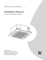
Evacuation Instructions
Before using manifold gauge and vacuum pump, read their
operation manuals to familiarize yourself with how to use
them properly.
Manifold Gauge
Compound gauge
--76cmH
Low pressure valve
High pressure valve
Charge hose
Charge hose
Vacuum pump
Pressure gauge
Low pressure valve
Fig. 9.1
1. Connect the charge hose of the manifold gauge to
service port on the outdoor unit’s low pressure valve.
2. Connect another charge hose from the manifold gauge
to the vacuum pump.
3. Open the Low Pressure side of the manifold gauge.
Keep the High Pressure side closed.
4. Turn on the vacuum pump to evacuate the system.
5. Run the vacuum for at least 15 minutes, or until the
Compound Meter reads -76cmHG (-1x10⁵Pa).
6. Close the Low Pressure side of the manifold gauge, and
turn o the vacuum pump.
7. Wait for 5 minutes, then check that there has been no
change in system pressure.
NOTE:
the table above refer to the liquid tube.
The number of bends is up to the length of the max height drop.
Usually for each 10m need a bend.
If a negative result is gotten for R from Table 9-1, no refrigerant
needs to be added nor removed.
Additional refrigerant will be twice of R from Table 9-1 if the indoor
unit installed throttle assembly.
NOTE: If the re is no change in system p ressure, unscrew
the cap f rom the packed valve (high p ressure valve). If
there is a change in system p ressure, the re may be a gas
leak.
Note On Adding Refrigerant
8. Insert hexagonal wrench into the packed valve (high
pressure valve) and open the valve by turning the
wrench in a 1/4 counterclockwise turn. Listen for gas to
exit the system, then close the valve after 5 seconds.
Flare nut
Cap
V alve body
V alve stem
Fig. 9.2
9. Watch the Pressure Gauge for one minute to make su re
that there is no change in p ressure. The P ressure Gauge
should read slightly higher than atmospheric p ressure.
10. Remove the charge hose f rom the service port.
11. Using hexagonal w rench, fully open both the high
pressure and low p ressure valves.
OPEN VA LVE STEMS GENT LY
When opening valve stems, tu rn the hexagonal w rench
until it hits against the stoppe r. DO NOT try to fo rce the
valve to open furthe r.
12. Tighten valve caps by hand, then tighten it using the
proper tool.
CAUTION
• Refrigerant charging must be performed after
wiring, vacuuming and the leak test.
• DO NOT exceed the maximum allowable quantity
•
of refrigerant or ove rcharge the system. Doing so
can damage or impact the unit ’s function.
Charging with unsuitable substances may cause
explosions or accidents. Ensure that the appropriate
refrigerant is used.

13
installation manual
10. WIR
Connect the connective cables to the terminals as identified
with their respective mached numbers on the terminal block
of indoor and outdoor units.
Re-install the cover or the protection board.
10.1
Connect the cable
10.2
The Specification of Power
10.3
Wiring figure
(Refer to Table10-1~Table 10-8)
(Refer to Fig.10-3~Fig.10-6)
Remove the electric cover of the outdoor unit.
If there is no cover on the outdoor unit, disassemble
the bolts f rom the maintenance boa rd and remove the
protection board. (See Fig. 10.1, 10.2)
Cover
Screw
Fig. 10.1
Protection Board
Fig. 10.2
NOTE:
Remark per EMC Directive 2004/108/EC.
For to prevent flicker impressions during the start of the
compressor (technical process), following installation conditions
do apply.
1. The power connection for the air conditioner has to be done at
the main power distribution. The distribution has to be of a low
impedance, normally the required impedance reaches at a 32 A
fusing point.
2.. No other equipment has to be connected with this power lin
3.. For detailed installation acceptance please refer to your pow
supplier, if restrictions do apply for products like washing
machines, air conditioners or electrical ovens.
4.. For power details of the air conditioner refer to the rating pla
of the product.
5.. For any question contact your local dea r.
The appliance shall be installed in accordance with national
wiring regulations.
The air conditioner should use separate power supply with
rated voltage.
The external power supply to the air conditioner should
have ground wiring, which is linked to the ground wiring
of the indoor and outdoor unit.
The wiring work should be done by qualified persons
according to circuit drawing.
An all-pole disconnection device which has at least 3mm
sepaaration distance in all pole and a residual current
device (RCD) with the rating of above 10mA shall be
incorporated in the fixed wiring according to the national
rule.
Be sure to locate the power wiring and the signal wring
well to avoid cross-disturbance.
Do not turn on the power until you have checked carefully
after wiring.
The power cord type designation is H07RN-F.
I.. Whether the air conditione heats well in the case of the
HEATING/COOLING type.
2) The outdoor unit
a.. Whether there is vibration or abnormal noise duri
operation.
b. Whether the generated wind, noise, or condensed of by
the air conditioner have influenced your neighborhood.
c.. Whether any of the refrigerant is leake
A protection feature prevents the air conditioner from being
activated for approximately 3 minutes when it is restarted
immediately after shut off.
CAUTION
1) The indoor unit
a.. Whether the switch on the remote controller works wel
b.. Whether the buttons on the remote controller wor
well.
c.. Whether the air flow louver moves normal .
d.. Whether the room temperature is adjusted wel
e.. Whether the indicator lights normal .
f.. Whether the temporary buttons works wel
g.. Whether the drainage is norma
h.. Whether there is vibration or abnormal noise duri
operation.
4
According to the user's requirement, install the remote
controller frame where the remote controller's signal can
reach the indoor unit smoothly.
Test operation
Set the air conditioner under the mode of "COOLING" with
the remote controller, and check the following points. If there
is any malfunction, please resolve it according to the chapter
"Troubleshooting" in the "Owner's Manual".
11.. TEST OP TION
The test operation must be carried out after the entire
installation has been completed.
Please confirm the following points before the test operation:
2
1
3
The indoor unit and outdoor unit are installed properly.
Tubing and wiring are correctly completed.
The refrigerant pipe system is leakage-checked.
The drainage is unimpeded.
The heating insulation works well.
The ground wiring is connected correctly.
The length of the tubing and the added stow capacity of
the refrigerant have been recorded.
The power voltage fits the rated voltage of the air
conditioner.
There is no obstacle at the outlet and inlet of the outdoor
and indoor units.
The gas-side and liquid-side stop valves are both opened.
The air conditioner is pre-heated by turning on the power.

14
installation manual
Table 10-1
Table 10-2
The Specification of Power(indoor power supply)
The Specification of Power(outdoor power supply)
20
/16 40/25 50/30 60/45 60/50
40/30 60/40 70/55 70/60
MODEL
POWER
CIRCUIT BREAKER/FUSE(A)
PHASE
FREQUENCY AND VOLT
18 24 60 30~36 42~48
208-240V 208-240V
1Phase 1Phase
208-240V
1Phase
208-240V
1Phase
208-240V
1Phase
MODEL
POWER
CIRCUIT BREAKER/FUSE(A)
PHASE
FREQUENCY AND VOLT
30~36 30~36
42~60 42~60
380-420V
25/20 25/20 40/25 45/35
208-240V
3Phase
380-420V
3Phase 3Phase
208-240V
3Phase
Table 10-3
Table 10-4
MODEL
POWER
CIRCUIT BREAKER/FUSE(A)
PHASE
FREQUENCY AND VOLT
24 60 30~36 42~48
208-240V
1Phase
20/16
12~18
208-240V
1Phase
208-240V
1Phase
208-240V
1Phase
208-240V
1Phase
MODEL
POWER
CIRCUIT BREAKER/FUSE(A)
PHASE
FREQUENCY AND VOLT
30~36 30~36
42~60 42~60
380-420V
25/20 25/20 40/25 45/35
208-240V
3Phase
380-420V
3Phase 3Phase
208-240V
3Phase

15
installation manual
The Specification of Power(independence power supply)
20/16 40/25 50/30 60/45 60/50
208-240V 208-240V
1Phase 1Phase
208-240V
1Phase
208-240V
1Phase
208-240V
1Phase
MODEL
POWER
(indoor)
POWER
(outdoor)
CIRCUIT BREAKER/FUSE(A)
CIRCUIT BREAKER/FUSE(A)
PHASE
FREQUENCY AND VOLT
PHASE
FREQUENCY AND VOLT
18 24 60 30~36 42~48
208-240V 208-240V
1Phase 1Phase
208-240V
1Phase
208-240V
1Phase
208-240V
1Phase
20/16 20/16 20/16 20/16 20/16
208-240V
1Phase
208-240V
1Phase
208-240V
1Phase
208-240V
1Phase
20/16 20/16 20/16 20/16
MODEL
CIRCUIT BREAKER/FUSE(A)
CIRCUIT BREAKER/FUSE(A)
PHASE
FREQUENCY AND VOLT
30~36 30~36
42~60 42~60
380-420V
25/20 25/20 40/25 45/35
208-240V
3Phase
380-420V
3Phase 3Phase
208-240V
3Phase
Table 10-5
Table 10-6
PHASE
FREQUENCY AND VOLT
POWER
POWER
(indoor)
(indoor)
POWER
POWER
(outdoor)
(outdoor)
30/20 30/20 40/30 40/35 50/40
208-240V 208-240V
1Phase 1Phase
208-240V
1Phase
208-240V
1Phase
208-240V
1Phase
MODEL
POWER
(indoor)
POWER
(outdoor)
CIRCUIT BREAKER/FUSE(A)
CIRCUIT BREAKER/FUSE(A)
PHASE
FREQUENCY AND VOLT
PHASE
FREQUENCY AND VOLT
18 24 60 30~36 42~48
220-240V 220-240V
1Phase 1Phase
220-240V
1Phase
220-240V
1Phase
220-240V
1Phase
15/10 15/10 15/10 15/10 15/10
220-240V
1Phase
220-240V
1Phase
220-240V
1Phase
220-240V
1Phase
15/10 15/10 15/10 15/10
MODEL
CIRCUIT BREAKER/FUSE(A)
CIRCUIT BREAKER/FUSE(A)
PHASE
FREQUENCY AND VOLT
30~36 30~36
42~60 42~60
380-420V
30/20 30/25 50/40 50/40
208-240V
3Phase
380-420V
3Phase 3Phase
208-240V
3Phase
The Specification of Power for the invert type air conditioner(independence power supply)
Table 10-7
Table 10-8
PHASE
FREQUENCY AND VOLT
POWER
POWER
(indoor)
(indoor)
POWER
POWER
(outdoor)
(outdoor)

16
installation manual
The power supply is included in the power supply above mentioned can be applied to the table.
Before obtaining access to terminals, all supply circuits must be disconnected.
CAUTION
Wiring figure
Fig.10-3
Fig.10-4
Ground wiring
Ground wiring
Power supply
Switch/Fuse
(Available locally)
Power wiring (indoor)
Power linking wiring (Outdoor)
Strong elec-signal link wiring
Weak elec-signal link wiring
Indoor
Unit
Outdoor
Unit
Ground the air conditioner properly in case to affect its anti-interference function
Ground wiring
Ground wiring
Power supply
Switch/Fuse
(Available locally)
Power wiring (outdoor)
Power linking wiring (indoor)
Strong elec-signal link wiring
Weak elec-signal link wiring
Indoor
Unit
Outdoor
Unit
Ground the air conditioner properly in case to affect its anti-interference function

17
installation manual
Fig.10-5
Ground wiring
Power supply
Switch/Fuse
(Available locally)
Power wiring (indoor)
Power linking wiring (Outdoor)
Ground wiring
Weak elec-signal link wiring
Indoor
Unit
Out door
Unit
Power supply
Ground the air conditioner properly in case to affect its
anti-interference function
A disconnection device having an air gap contact separation in all active conductors should be
incorporated in the fixed wiring according to the National Wiring Regulation.
When wiring, please choose the corresponding chart, or it may cause damage.The signs of the
indoor terminal block in the some of following fugures may be replaced by L N L1 N1.
CAUTION
Fig.10-6
Ground wiring
Ground wiring
Power supply
Switch/Fuse
(Available locally)
Power wiring (outdoor)
Strong elec-signal link wiring
Weak elec-signal link wiring
Indoor
Unit
Outdoor
Unit
Ground the air conditioner properly in case to affect its anti-interference function

18
installation manual
The design and specifications are subject to change without prior notice for product
improvement.Consult with the sales agency or manufacturer for details.
2190 NW 89 Place, Doral, FL 33172 - USA
Tel: (305)593-8358 Fax (305) 675-2212
www.klimaire.com [email protected]
The Klimaire logo is a registered Trademark of Klimaire Products inc.
Copyright 2016 Klimaire Products Inc.
/