Page is loading ...

MULTI-ZONE
DUCTLESS INVERTER
SPLIT AIR CONDITIONER
WITH HEAT PUMP
•INSTALLATION
MANUAL•
SLIM DUCT TYPE
INDOOR UNIT
IMPORTANT NOTE:
• Read this manual carefully before
installing or operating your new air
conditioning unit. Make sure to save
this manual for future reference.

Accessories....................................................04
".
Indoor Unit Parts
.......................................07
#. Indoor Unit Installation Instructions. .....0
Safety Precautions . ....................................05
Outdoor Unit Installation......................... 18
". Outdoor Unit Installation Instructions......18
B. Drain Joint Installation..........................20
C.
Notes on Drilling Hole in Wall
...................20
Drainpipe Installation. ..............................21
Table of Contents
Installation Manual
Indoor Unit Installation
..........................07
Installation Overview ...............................06
1
2
5
3
4
6

Page 3
Refrigerant Piping Connection......................23
A. Notes on Pipe Length and Elevation ............. 23
B. Refrigerant Piping Connection Instructions ..24
Wiring. ............................................... 26
".
Outdoor Unit Wiring...................26
#.
Indoor Unit Wiring
......................27
$.
Power Specifications
..................28
Air Evacuation................................................. 30
". Evacuation Instructions................................ 30
#. Note on Adding Refrigerant....................... 31
Test Run.............................................32
MC MC
7
8
9
10
L N

Page 4
Accessories
1
The air conditioning system comes with the following accessories. Use all of the installation parts
and accessories to install the air conditioner. Improper installation may result in water leakage,
electrical shock and fire, or equipment failure.
Connecting wire for display (2m)
Cord protection rubber ring
QUANTITY
SHAPENAME
Soundproof/insulation sheath
2
1
1
1
1
Tubing & Fittings
Others
Installation manual
1
6TFS‘s manual
Drain joint (some models)
Seal ring (some models)
Drainpipe Fittings
(for cooling & heating)
Binding tape
1
Seal sponge (some models)
Orifice (some models)
1
Transfer connector(Φ12.7-Φ15.9)Φ0.5in-
( )
Φ0.63in
(Packed with the indoor unit)
NOTE: Pipe size may
differ from appliance to
appliance. To meet different pipe size requirements,
sometimes the pipe connections need a transfer
connector installed on the outdoor unit.
5SBOTGFSDPOOFDUPS͖͖͖JO͖JO
1BDLFEXJUIUIFJOEPPSVOJU
NOTE: Pipe size may differ from appliance to
appliance. To meet different pipe size requirements,
sometimes the pipe connections need a transfer
connector installed on the outdoor unit.
Transfer connector(Φ9.52-Φ12.7)/
Φ0.375in-
( )
Φ0.5in
(Packed with the indoor unitused for multi-type
models only)
NOTE: Pipe size may differ from appliance to
appliance. To meet different pipe size requirements,
sometimes the pipe connections need a transfer
connector installed on the outdoor unit.
1
(on some models)
1
(on some models)
1
(on some models)
1(on some models)
1(on some models)
Optional accessories
There are two types of remote controls: wired and wireless.
Select a remote control based on customer preferences and requirements and install in an
appropriate place.
Refer to DBUBMPHT and technical literature for guidance on selecting a suitable remote control.
•
1
1
EMC Magnetic
Ring (some
models)
Magnetic ring (wrap the electric wires S1
& S2 P & Q & E) around the magnetic
ring twice)
Magnetic ring(Iitch it on the connective
cable between UIFindoor unit and
outdoor unitT after installation)
S1&S2(P&Q&E)

Page 5
Safety Precautions
2
Read Safety Precautions Cefore Installation
Incorrect installation due to ignoring instructions can cause serious damage or injury.
The seriousness of potential damage or injuries is classified as either a WARNING or BCAUTION.
WARNING
• Carefully read the Tafety Qrecautions before installation.
• In certain functional environments, such as kitchens, server rooms, etc., the use of specially
designed airconditioning units is highly recommended.
• Only trained and certified technicians should install, repair and service this air
conditioning unit.
Improper installation may result in electrical shock, short circuit, leaks, fire or other damage to
the equipment and personal property.
• Strictly follow the installation instructions set forth in this manual.
Improper installation may result in electrical shock, short circuit, leaks, fire or other damage to
the equipment.
• Before you install the unit, consider strong winds, typhoons and earthquakes that might
affectyour unit and locate it accordingly. Failure to do so could cause the equipment to fail.
• After installation, ensure there are no refrigerant leaks and that the unit is operating properly.
Refrigerant is both toxic and flammable and poses a serious health and safety risk.
Note about Fluorinated Gases
This airconditioning unit contains fluorinated gases. For specific information on the type of gas
and the amount, please refer to the relevant label on the unit itself.
Installation, service, maintenance and repair of this unit must be performed by a certified
technician.
Product uninstallation and recycling must be performed by a certified technician.
If the system has a leak-detection system installed, it must be checked for leaks at least every 12
months.
When the unit is checked for leaks, proper record-keeping of all checks is strongly recommended.
Failure to observe a warning may result in death. The appliance must be installed in
accordance with national regulations.
Failure to observe a caution may result in injury or equipment damage.
WARNING
CAUTION

Page 6
Installation Overview
3
Unit Installation
Overview
LN
1
2
3
4
5
MC MC
6
7
Install the indoor unit
(Page 7)
INSTALLATION ORDER
Install the outdoor unit
(Page 18)
Install the drainpipe
(Page 21)
Evacuate the refrigeration system
(Page 30)
Connect the wires
(Page 26)
Connect the refrigerant pipes
(Page 23)
Perform a test run
(Page 32)

Page 7
Indoor Unit Installation
4
Indoor Unit
Installation
Indoor Unit Parts
Fig. 4.1
Air inlet
Air outlet
Air filter (on some models)
Drain hose
Electric control cabinet
Refrigerant connecting pipe
Safety Precautions
WARNING
• Securely install the indoor unit on a structure
that can sustain its weight. If the structure is
too weak, the unit may fall causing personal
injury, unit and property damage, or even
death
• DO NOT install the indoor unit in a bathroom
or laundry room as excessive moisture can
short the unit and corrode the wiring.
CAUTION
• Install the indoor and outdoor units, cables
and wires at least 1m (3.2GU) from
televisionsor radios to prevent static or
imagedistortion. Depending on the
appliances, a1m (3.2GU) distance may not
be sufficient.
• If the indoor unit is installed on a metal
part of the building, it must be grounded.
Indoor Unit Installation Instructions
Step 1: Select installation location
The indoor unit should be installed in a location
that meets the following requirements:
Enough room for installation and maintenance.
Enough room for the connecting pipe and
drainpipe.
The ceiling is horizontal and its structure can
sustain the weight of the indoor unit.
The air inlet and outlet are not impeded.
The airflow can fill the entire room.
There is no direct radiation from heaters.
CAUTION
DO NOT install the unit in the following
locations:
Where oil drilling or fracking is taking place
Coastal areas with high salt content in the air
Near geothermal activity and corrosive gas
Buildings that may experience power
fluctuations
Enclosed spaces
Areas with strong electromagnetic waves
Areas that store flammable materials or gas
Rooms with high humidity, such as
bathrooms or laundry rooms
Fig. 4.2
checking orifice
60cmYX60cm
30cm or more
20cm or more
Maintenance roomage
√
√
√
√
√
√

Page 8
Indoor Unit
Installation
Fig. 4.3
Step 2: Hang indoor unit
1. Please refer to the following diagrams to locate the four positioning screw bolt holes on the
ceiling. Be sure to mark the paces where you will drill ceiling hook holes.
Air outlet dimensions(Bpplicable to 18-36K series only)
Air inlet dimensions
Air filter
Descending ventilation opening
Air filter
Electric control box
Size of mounted hook
Electric control box
Table4-1
(unit: mm/in)
MODEL
(Btu/h)
Outline dimension
A
B
C
≤12K 210/8.2 635/25
700/27.6
12K18K 210/8.2
635/25920/36.2
24K
270/10.6
635/25920/36.2
36Ksmall model
270/10.6 635/25920/36.2
30K36K
270/10.6 775/30.51140/44.9
42K60K
300/11.8 865/341200/47.2
"ir outlet opening size
D E F
65/2.6 493/19.4570/22.4
65/2.6
713/28
570/22.4
65/2.6
713/28
570/22.4
65/2.6
713/28
570/22.4
65/2.6 933/36.7
710/28
80/3.1 968/38.1800/31.5
"ir return opening size
G
HI
119/4.7 595/23.435/1.4
119/4.7 815/32
35/1.4
179/7 815/32
35/1.4
179/7 815/32
35/1.4
179/7 1035/40.7
35/1.4
204/8 1094/43
40/1.6
Size of mounted lug
JKL
80/3.2 740/29200/7.9
80/3.2 960/37.8200/7.9
20/0.78
960/37.8
260/10.2
20/0.78
960/37.8260/10.2
20/0.78 1180/46.5
260/10.9
45/1.8
1240/48.8
288/11.3
M
350/13.8
350/13.8
350/13.8
350/13.8
490/19.3
500/19.7

Page 9
Indoor Unit
Installation
Cut off the roof beam.
Strengthen the point at which the cut
was made. Consolidate the roof beam.
Fig. 4.6
Fig. 4.7
Original concrete bricks
Use embedding screw bold, crock and
stick harness.(Refer to Fig.46)
Steel roof beam structure
Install and use the supporting steel angle.
(See Fig.4.7)
Fig. 4.4
Wood
Place the wood mounting across the roof beam,
then install the hanging screw bolts.(See Fig.4.4)
Wood mounting
Roof beam
Hanging screw bolts
Ceiling
Fig. 4.5
New concrete bricks
Inlay or embed the screw bolts. (See Fig. 4.5)
(Blade shape insertion)
(Slide insertion)
Steel bar
Embedding screw bolt
(Pipe hanging and embedding screw bolt)
Hanging screw bolt
Hanging
bolts
Supporting
angle steel
Fig. 4.9
Screw nut
Washer
Hanging screw bolt
Overhang part
Shockproof cushion
NOTE:
Confirm the minimum drain tilt is 1/100
or more.
CAUTION
The unit body must be completely aligned with
the hole. Ensure that the unit and the hole are
the same size before moving on.
2. Install and fit pipes and wires after you have
finished installing the main body.When
choosing where to start, determine the
direction of the pipes to be drawn out.
Especially in cases where there is a ceiling
involved, align the refrigerant pipes, drain
pipes, and indoor and outdoor lines with their
connection points before mounting the unit.
3.
Install hanging screw bolts.
After you select an installation location,align
the refrigerant pipes, drain pipes, aOEindoor
and outdoor wires with theirconnection
points before mounting the unit.
Drill 4 holes 10cm (4JO) deep at the ceiling
hook positions in the internal ceiling. Be sure
to hold the drill at a 90° angle to the ceiling.
Secure the bolt using the washers and nuts
provided.
Install the four suspension bolts.
Mount the indoor unit with at least two
people to lift and secure it. Insert suspension
bolts into the unit’s hanging holes. Fasten
them using the washers and nuts provided.
(See Fig. 4.8)
9. Mount the indoor unit onto the hanging
screw bolts with a block. Position the
indoor unit flat using a level indicator to
prevent leaks. (See Fig. 4.9)
Fig. 4.8

Page 10
Indoor Unit
Installation
Fig. 4.10
NOTE: 1.Do not put the connecting duct
weight on the indoor unit.
When connecting the duct, use a
nonflammable canvas tie-in to prevent
vibrating.
Insulation foam must be wrapped outside the
duct to avoid condensatJPO. An internal duct
VOEFSMBZFS can be added to reduce noise,
if the end-user requiresJU.
Step 4: Control (only for inverter units)
The capacity of the system and the
network address of the airconditioner can
be set by the switches on the indoor Main
Control Board.
Before setting, turn off the power. After
setting, restart the unit.
Setting is not QPTTJCMF when the unit is
powerFE on.
Table 4-3
1 Horsepower code setting
The capacity of the indoor unit has been set
in the factory according to the UBCMFbelow
Horsepower code
ENC1
POWER_S
0
1
2
3
4
5
6
7
8
9
A
B
C
D
E
F
ENC1
Note: The
capacity has
been set in the
factory/PPOF
can adjust it
except B
qualified person.
Toggle switch Dode Capacity(kw)
4
5.3
5.6
5
7.1
7
9.0
8
10.5
9
14.0
16.0
2 Network address set
Every airconditioner in UIFnetwork has only
one EJTUJOHVJTIJOHnetwork address. 5IF
Bddress code of UIFairconditioner in LAN is set
by code switches S1 & S2 on the Main Control
Board of the indoor unit, and the set range is
0-63.
Table 4-4
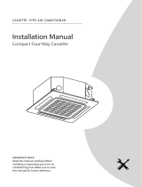
Step 3: Duct and accessories installation
1.
Install the filter(optional) according to air inlet size.
5. Refer to the following static pressure guidelines
when installing the indoor unit.
Change the fan motor static pressure
according to external duct static pressure.
2.
3.
Install the canvas tie-in between the body and duct.
The air inlet and air outlet ductT should be far
enough apart to avoid BOair passageshort-
circuit.
4. Connect the duct according to the following
diagram:
Canvas tie-in Canvas tie-in
Air outlet
Isolation booth
Isolation booth
$hecking orifice
Air inlet
Air dust filter
Table4-2
MODEL
(Btu/h)
Static Pressure
(Pa)
30
12K
70
18K
70
24K
80
30K36K
100
42K60,

Page 11
Indoor Unit
Installation
Step 5: Adjust the air inlet direction
(Grom rear side to underside)
1. Take off UIFventilation panel and flange, UIFO
cut off
the staples atUIF side rail.
2. Stick the attached seal sponge JO the
indicated place in the following figure,
then change the mounting positions of the
air returnpanel and UIFair return flange.
Air return flange
Side rail
Dentilation panel
Seal sponge
3. When installing the filter mesh, fit it into the
flange inclined from theair return opening,
then push up.
4. When installation Js finishFE, upon filter
mesh which fixing blocks have been insert to
the flange positional holes.
NOTE:
All the figures in this manual are for
demonstration purposes only. The air conditioner
you have purchased may be slightly different in
design, though similar in shape.
Step 6: Fresh air duct installation
Dimension:
Duct joint for fresh air
80mm(3.15JO)
80mm(3.15JO)
Ø90mm(3.54JO)
Ø125mm(4.92JO)
Ø160mm(6.3JO)
MODLE
12-24 30-60
Step 7: Motor and drain pump maintenance
Motor maintain:
Take off the ventilated panel.
Take off the blower housing.
Take off the motor.
1.
2.
3.
(5he rear ventilated panel is used as an example)
MoUor
Blower housing
Ventilated panel
Pump maintenance
Remove four screws from the drain pump.
Unplug the pump power supply and water
level switch cable.
Detach the pump.
1.
2.
3.
Pump

Page 12
Indoor Unit
Installation
Fan performances
Static pressure curve(middle static pressure
duct)
Code 0
Code 1
Code 2
Code 3
Code 4
External stac pressure in. WG (Pa)
Air volume CFM (m3/h)
Limit
High
Middle
Low
Rated Point
176 235 294 353 412
(300) (400) (500) (600)
(700)
0.08
(20)
0.06
(15)
0.04
(10)
0.02
(5)
0
External stac pressure in. WG (Pa)
Air volume CFM (m3/h)
High
Middle
Low
Limit
Rated Point
0.12
(30)
0.10
(25)
0.08
(20)
0.06
(15)
0.04
(10)
0.02
(5)
0
176 235 294 353 412
(300) (400) (500) (600) (700)
External stac pressure in. WG (Pa)
Air volume CFM (m3/h)
High
Limit
Low
Rated Point
0.16
(40)
0.14
(35)
0.12
(30)
0.10
(25)
0.08
(20)
0.06
(15)
0.04
(10)
0.02
(5)
0
176 235 294 353 412
(300) (400) (500) (600) (700)
External stac pressure in. WG (Pa)
Air volume CFM (m3/h)
High
Limit
Low
Rated Point
0.20
(50)
0.18
(45)
0.16
(40)
0.14
(35)
0.12
(30)
0.10
(25)
0.08
(20)
0.06
(15)
0.04
(10)
0.02
(5)
0
176 235 294 353 412
(300) (400) (500) (600)
(700)
External stac pressure in. WG (Pa)
Air volume CFM (m3/h)
High
Limit
Low
Rated Point
176 235 294 353 412
(300) (400) (500) (600) (700)
0.20
(50)
0.18
(45)
0.16
(40)
0.14
(35)
0.12
(30)
0.10
(25)
0.08
(20)
0.06
(15)
0.04
(10)
0.02
(5)
0

Page 13
Code 0
Code 1
Code 2
Code 3
Code 4
External stac pressure in. WG (Pa)
Air volume CFM (m3/h)
High
Low
Limit
Rated Point
0.08
(20)
0.06
(15)
0.04
(10)
0.02
(5)
0
206 265 324 382 441
(350) (450) (550)
(650) (750)
External stac pressure in. WG (Pa)
Air volume CFM (m3/h)
High
Middle
Low
Limit
Rated Point
0.10
(25)
0.08
(20)
0.06
(15)
0.04
(10)
0.02
(5)
0
206 265 324 382 441
(350) (450)
(550)
(650) (750)
External stac pressure in. WG (Pa)
Air volume CFM (m3/h)
Limit
High
Middle
Low
Rated Point
0.14
(35)
0.12
(30)
0.10
(25)
0.08
(20)
0.06
(15)
0.04
(10)
0.02
(5)
0
206 265 324 382 441
(350) (450)
(550)
(650) (750)
External stac pressure in. WG (Pa)
Air volume CFM (m3/h)
Limit
Low
High
Rated Point
0.20
(50)
0.16
(40)
0.12
(30)
0.08
(20)
0.04
(10)
0
206 265 324 382 441
(350) (450) (550) (650) (750)
External stac pressure in. WG (Pa)
Air volume CFM (m3/h)
Limit
Low
Rated Point
206 265 324 382 441
(350) (450)
(550)
(650) (750)
0.24
(60)
0.20
(50)
0.16
(40)
0.12
(30)
0.08
(20)
0.04
(10)
0
12K
Indoor Unit
Installation

Page 14
Indoor Unit
Installation
Code 0
Code 1
Code 2
Code 3
Code 4
External stac pressure in. WG (Pa)
Air volume CFM (m3/h)
Limit
High
Low
Rated Point
176 235 294 353 412 471 529 588 647
(300) (400) (500) (600) (700) (800) (900) (1000) (1100)
0.16
(40)
0.14
(35)
0.12
(30)
0.10
(25)
0.08
(20)
0.06
(15)
0.04
(10)
0.02
(5)
0
External stac pressure in. WG (Pa)
Air volume CFM (m3/h)
Low
Limit
High
Rated Point
0.20
(50)
0.16
(40)
0.12
(30)
0.08
(20)
0.04
(10)
0
176 235 294 353 412 471 529 588 647
(300) (400) (500) (600) (700) (800) (900) (1000) (1100)
External stac pressure in. WG (Pa)
Low
High
Limit
Rated Point
176 235 294 353 412 471 529 588 647
(300) (400) (500) (600) (700) (800) (900) (1000) (1100)
Air volume CFM (m3/h)
0.24
(60)
0.20
(50)
0.16
(40)
0.12
(30)
0.08
(20)
0.04
(10)
0
External stac pressure in. WG (Pa)
Air volume CFM (m3/h)
Low
Limit
High
Rated Point
0.32
(80)
0.28
(70)
0.24
(60)
0.20
(50)
0.16
(40)
0.12
(30)
0.08
(20)
0.04
(10)
0
176 235 294 353 412 471 529 588 647
(300) (400) (500) (600) (700) (800) (900) (1000) (1100)
External stac pressure in. WG (Pa)
Air volume CFM (m3/h)
Low
Limit
High
0.32
(80)
0.28
(70)
0.24
(60)
0.20
(50)
0.16
(40)
0.12
(30)
0.08
(20)
0.04
(10)
0
176 235 294 353 412 471 529 588 647
(300) (400) (500) (600) (700) (800) (900) (1000) (1100)
18K

Page 15
Indoor Unit
Installation
Code 0
Code 1
Code 2
Code 3
Code 4
24K
External stac pressure in. WG (Pa)
Air volume CFM (m3/h)
Rated Point
High
Limit
Middle
Low
353 471 588 706 824 941
(600) (800) (1000) (1200) (1400) (1600)
0.20
(50)
0.16
(40)
0.12
(30)
0.08
(20)
0.04
(10)
0
External stac pressure in. WG (Pa)
Air volume CFM (m3/h)
Rated Point
High
Limit
Middle
Low
0.24
(60)
0.20
(50)
0.16
(40)
0.12
(30)
0.08
(20)
0.04
(10)
0
353 471 588 706 824 941
(600) (800) (1000) (1200) (1400) (1600)
External stac pressure in. WG (Pa)
Air volume CFM (m3/h)
Rated Point
High
Limit
Middle
Low
0.32
(80)
0.28
(70)
0.24
(60)
0.20
(50)
0.16
(40)
0.12
(30)
0.08
(20)
0.04
(10)
0
353 471 588 706 824 941
(600) (800) (1000) (1200) (1400) (1600)
External stac pressure in. WG (Pa)
Air volume CFM (m3/h)
0.40
(100)
0.36
(90)
0.32
(80)
0.28
(70)
0.24
(60)
0.20
(50)
0.16
(40)
0.12
(30)
0.08
(20)
0.04
(10)
0
Rated Point
High
Limit
Middle
Low
353 471 588 706 824 941
(600) (800) (1000) (1200) (1400) (1600)
External stac pressure in. WG (Pa)
Air volume CFM (m3/h)
Rated Point
High
Limit
Middle
Low
0.40
(100)
0.36
(90)
0.32
(80)
0.28
(70)
0.24
(60)
0.20
(50)
0.16
(40)
0.12
(30)
0.08
(20)
0.04
(10)
0
353 471 588 706 824 941
(600) (800) (1000) (1200) (1400) (1600)

Page 16
Indoor Unit
Installation
Code 0
Code 1
Code 2 Code 3
Code 4
36K
External stac pressure in. WG (Pa)
Middle
High
Limit
Low
Rated Point
471 588 706 824 941 1059 1176 1294
(800) (1000) (1200) (1400) (1600) (1800) (2000) (2200)
Air volume CFM (m3/h)
0.28
(70)
0.24
(60)
0.20
(50)
0.16
(40)
0.12
(30)
0.08
(20)
0.04
(10)
0
External stac pressure in. WG (Pa)
Air volume CFM (m3/h)
0.28
(70)
0.24
(60)
0.20
(50)
0.16
(40)
0.12
(30)
0.08
(20)
0.04
(10)
0
Middle
High
Limit
Low
Rated Point
471 588 706 824 941 1059 1176 1294
(800) (1000) (1200) (1400) (1600) (1800) (2000) (2200)
External stac pressure in. WG (Pa)
Air volume CFM (m3/h)
Low
Middle
High
Limit
Rated Point
0.32
(80)
0.28
(70)
0.24
(60)
0.20
(50)
0.16
(40)
0.12
(30)
0.08
(20)
0.04
(10)
0
471 588 706 824 941 1059 1176 1294
(800) (1000) (1200) (1400) (1600) (1800) (2000) (2200)
External stac pressure in. WG (Pa)
Air volume CFM (m3/h)
0.40
(100)
0.36
(90)
0.32
(80)
0.28
(70)
0.24
(60)
0.20
(50)
0.16
(40)
0.12
(30)
0.08
(20)
0.04
(10)
0
Limit
High
Low
Rated Point
471 588 706 824 941 1059 1176 1294
(800) (1000) (1200) (1400) (1600) (1800) (2000) (2200)
External stac pressure in. WG (Pa)
Air volume CFM (m3/h)
Limit
High
Middle
Low
Rated Point
0.40
(100)
0.36
(90)
0.32
(80)
0.28
(70)
0.24
(60)
0.20
(50)
0.16
(40)
0.12
(30)
0.08
(20)
0.04
(10)
0
471 588 706 824 941 1059 1176 1294
(800) (1000) (1200) (1400) (1600) (1800) (2000) (2200)

Page 17
Indoor Unit
Installation
Code 0 Code 1
Code 2
Code 3
Code 4
48K
External stac pressure in. WG (Pa)
Air volume CFM (m3/h)
588 706 824 941 1059 1176 1294 1412 1529
(1000) (1200) (1400) (1600) (1800) (2000) (2200) (2400) (2600)
0.24
(60)
0.20
(50)
0.16
(40)
0.12
(30)
0.08
(20)
0.04
(10)
0
High
Limit
Middle
Low
External stac pressure in. WG (Pa)
Air volume CFM (m3/h)
High
Limit
Middle
Low
0.32
(80)
0.28
(70)
0.24
(60)
0.20
(50)
0.16
(40)
0.12
(30)
0.08
(20)
0.04
(10)
0
588 706 824 941 1059 1176 1294 1412 1529
(1000) (1200) (1400) (1600) (1800) (2000) (2200) (2400) (2600)
External stac pressure in. WG (Pa)
Air volume CFM (m3/h)
High
Limit
Middle
Low
0.40
(100)
0.36
(90)
0.32
(80)
0.28
(70)
0.24
(60)
0.20
(50)
0.16
(40)
0.12
(30)
0.08
(20)
0.04
(10)
0
588 706 824 941 1059 1176 1294 1412 1529
(1000) (1200) (1400) (1600) (1800) (2000) (2200) (2400) (2600)
External stac pressure in. WG (Pa)
Air volume CFM (m3/h)
High
Limit
Middle
Low
0.40
(100)
0.36
(90)
0.32
(80)
0.28
(70)
0.24
(60)
0.20
(50)
0.16
(40)
0.12
(30)
0.08
(20)
0.04
(10)
0
588 706 824 941 1059 1176 1294 1412 1529
(1000) (1200) (1400) (1600) (1800) (2000) (2200) (2400) (2600)
External stac pressure in. WG (Pa)
Air volume CFM (m3/h)
Limit
Low
High
0.40
(100)
0.36
(90)
0.32
(80)
0.28
(70)
0.24
(60)
0.20
(50)
0.16
(40)
0.12
(30)
0.08
(20)
0.04
(10)
0
588 706 824 941 1059 1176 1294 1412 1529
(1000) (1200) (1400) (1600) (1800) (2000) (2200) (2400) (2600)

Outdoor Unit Installation
Outdoor Unit Installation Instructions
Step 1: Select installation location.
The outdoor unit should be installed in the
location that meets the following requirements:
Place the outdoor unit as close to the indoor
unit as possible.
Ensure that there is enough room for
installation and maintenance.
The air inlet and outlet must not be
obstructed or exposed to strong wind.
Ensure the location of the unit will not be
subject to snowdrifts, accumulation of leaves
or other seasonal debris. If possible, provide
an awning for the unit. Ensure the awning
does not obstruct airflow.
The installation area must be dry and well
ventilated.
There must be enough room to install the
connecting pipes and cables and to access
them for maintenance.
The area must be free of combustible gases
and chemicals.
The pipe length between the outdoor and
indoor unitT mVTU not exceed the maximum
allowable pipe length.
√ If possible, DO NOT install the unit where
itXJMMCF exposed to direct sunlight.
√ If possible, make sure the unit is located far
away from your neighbors’ property so that
noise from the unit will not disturb them.
√ If the location is exposed to strong winds (for
example: near a seaside), the unit must be
placed against B wall to shelter it from the
wind. If necessary, use an awning.
(See Fig. 5.1 & 5.2)
√ Install the indoor and outdoor units, cables
and wires at least 1 meter from televisions or
radios to prevent static or image distortion.
Depending on the radio waves, a 1 meter
distance may not be enough to eliminate all
interference.
Strong wind
Strong wind
Strong wind
Fig. 5.2Fig. 5.1
Step 2: Install outdoor unit
Fix the outdoor unit with anchor bolts (M10)
> 60cm / 23.6JO
Fix with bolts
CAUTION
• Be sure to remove any obstacles that
may block air circulation.
• Make sure you refer to Length
Specifications to ensure there is
enough room for installation and
maintenance.
Fig. 5.3
Page 18
Outdoor Unit
Installation
5
√
√
√
√
√
√
√
√

>120cm/47JO
Air Putlet
H
D
W
> 30cm/11.8JO
Air inlet
Air inlet
Air inlet
Air inlet
(Wall or obstacle)
> 30cm/11.8JO
> 30cm / 11.8JO
> 30cm/11.8JO
Table 5.1: Length Specifications of SplitType
Outdoor Unit (unit: mm/in)
Table 5.2: Length Specifications of
Vertical Discharge Outdoor Unit
(unit: mm/in)
MODEL
DJNFOTJPOT
WH D
18 633/25 554/21.8554/21.8
24 633/25 554/21.8554/21.8
36
759/29.8
554/21.8
554/21.8
36 633/25 600/23.6600/23.6
48 759/29.8 710/28710/28
60 843/33 710/28710/28
SplitType Outdoor Unit
(Refer to Fig 5.4, 5.5, 5.6, BOE5.10 and Table 5.1)
Vertical Discharge Type Outdoor Unit
(Refer to Fig 5.7, 5.8, BOE5.9 and Table 5.2)
(Wall or obstacle)
Fig. 5.7
Fig. 5.8
Fig. 5.9
Page 19
Outdoor Unit
Installation
Fig. 5.6
Fig. 5.5
A
B
D
W
H
W
H
Fig. 5.4
Outdoor Unit Dimensions
W x H x D
Mounting Dimensions
Distance A Distance B
760x590x285 (29.9x23.2x11.2) 530 (20.85) 290 (11.4)
810x558x310 (31.9x22x12.2) 549 (21.6) 325 (12.8)
845x700x320 (33.25x27.5x12.6) 560 (22) 335 (13.2)
900x860x315 (35.4x33.85x12.4) 590 (23.2) 333 (13.1)
945x810x395 (37.2x31.9x15.55) 640 (25.2) 405 (15.95)
990x965x345 (38.98x38x13.58) 624 (24.58) 366 (14.4)
946x810x420 (37.21x31.9x16.53) 673 (26.5)
403 (15.87)
950x1333x410 (37.4x52.48x16.14) 634 (24.96)
404 (15.9)
845x700x340 (33.25x27.5x13.38)
540 (21.26)
350 (13.8)
938x1369x392 (36.93x53.9x15.43) 634 (24.96) 404 (15.9)
900x1170x350 (35.4x46x13.8) 590 (23.2) 378 (14.88)
800x554x333 (31.5x21.8x13.1) 514 (20.24) 340 (13.39)

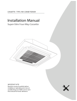
NOTE: The minimum distance between the
outdoor unit and UIFwalls described in the
installation guide does not apply to airtight
rooms. Be sure to keep the unit unobstructed
in at least two of the three directions (M, N, P)
(See Fig. 5.10)
M
N
P
30 cm/11.8JO from back wall
60 cm/23.6JO on right
60 cm/23.6JO above
30 cm/11.8JO on left
200 cm/78 inPO front
Fig. 5.10
Drain Joint Installation
Before bolting the outdoor unit in place, you
must install the drain joint at the bottom of the
unit. (See Fig. 5.12)
1. Fit the rubber seal on the end of the drain
joint that will connect to the outdoor unit.
2. Insert the drain joint into the hole in the
base pan of the unit.
3. Rotate the drain joint 90° until it clicks in
place facing the front of the unit.
4. Connect a drain hose extension (not
included) to the drain joint to redirect water
from the unit during heating mode.
NOTE: Make sure the water drains to a safe
location where it will not cause water damage
or a slipping hazard.
Seal
Drain joint
(A) (B)
Base pan hole of
UIFoutdoor unit
Seal
Fig. 5.12
Notes Pn Drilling Hole Jn Wall
You must drill a hole in the wall for the
refrigerant piping and GPSthe signal cable that
will connect the indoor and outdoor units.
Determine the location of the wall hole
based on the location of the outdoor unit.
Using a 65mm (2.5JO) core drill, drill a
holein the wall.
NOTE: When drilling the wall hole, make
sure to avoid wires, plumbing, and other
sensitive components.
3. Place the protective wall cuff in the hole.
This XJMMprotect the edges of the hole and
willhelp seal it when you finish the
installationprocess.
Page 20
Outdoor Unit
Installation
Fig. 5.11
L
H
300 cm / 118” or more
A
60 cm / 23.6”
or more
150 cm / 59”
or more
25 cm / 9.8”
or more
25 cm / 9.8”
or more
Rows of series installation
L ≤ H
L ≤ 1/2H
LA
25 cm/9.8JOor more
1/2H < L ≤ H
30 cm/11.8JO or more
L H
Cannot be installed
Table 5.3 The relations between H, A and L
are as follows
/