Page is loading ...

AutoDome Modular Camera System
VG4-100 Series
en User’s Manual

AutoDome, Bilinx, Bosch, the Bosch logo, DiBos, FastAddress and VIDOS are registered trademarks of Bosch Security Systems,
inc.
The following trademarks are registered with the United States Patent and Trademark Office:
Pentium is a registered trademark of Intel Corporation
.NET, DirectX, Internet Explorer, Microsoft, Windows, Windows 2000 and Windows XP are registered trademarks of Microsoft Cor-
poration
Due to the nature of this material, this document refers to numerous hardware and software products by their trade names, In
most, if not all cases, these designations are claimed as trademarks or registered trademarks by their respective companies in the
United States of America. It is not this publisher’s intent to use any of these names generically. The reader is therefore cautioned
to investigate all claimed trademark rights before using any of these names other than to refer to the product described.

AutoDome Modular Camera System | en iii
Bosch Security Systems, Inc. VG4-100 Series User’s Manual F01U028033 | 2.0 | 2007.03
Preface
This guide describes how to configure and control the VG4-100 Series AutoDome camera.
Audience
This guide is intended for operators who are familiar with CCTV concepts and configuration.
Document Conventions
Symbols
You may encounter these symbols within the document. Explanatory text accompanies each symbol, which provides
additional information detailing the operation or highlighting safety information.
Convention Meaning
Bold Denotes a part, item, or assembly.
Italic Denotes a reference to another paragraph, figure or table.
Underline Used to emphasize a point.
Courier Used to denote an item that is selected or must be typed exactly.
i
NOTICE! Notices inform you of essential but non-critical information. Read these
messages carefully as any directions or instructions contained therein can help you
avoid making mistakes.
!
CAUTION! Cautionary messages provide critical information that help you reduce the chance
of losing data or damaging the system. Please heed these messages.
!
WARNING! Warnings highlight information, that if overlooked may cause damage to the
system or result in personal injury. Take warnings seriously.

iv en | AutoDome Modular Camera System
F01U028033 | 2.0 | 2007.03 VG4-100 Series User’s Manual Bosch Security Systems, Inc.
Customer Support and Service
If this unit needs service, contact the nearest Bosch Security Systems Service Center for authorization to return and
shipping instructions.
Service Centers
USA
Phone: 800-366-2283 or 585-340-4162
Fax: 800-366-1329
Email: cctv.repai[email protected]osch.com
CCTV Spare Parts
Phone: 800-894-5215 or 408-957-3065
Fax: 408-935-5938
Email: [email protected].com
Canada
Phone: 514-738-2434
Fax: 514-738-8480
Europe, Middle East & Asia Pacific Region
Phone: 44 (0) 1495 274558
Fax: 44 (0) 1495 274280
Email: [email protected]
For additional information, see www.boschsecurity.com
Related Publications
Refer to the latest Bosch Security Systems Databook for the most up-to-date datasheets. To obtain a copy of the
Databook, please contact your local Bosch representative.
You can also visit the Bosch Security Systems World Wide Web site at:
http://www.boschsecurity.com to view a current listings of our publications.

AutoDome Modular Camera System Table of Contents | en v
Bosch Security Systems, Inc. VG4-100 Series User’s Manual F01U028033 | 2.0 | 2007.03
Table of Contents
1 Getting Started 3
2Camera Setup 3
3 Positioning the Camera 4
4 Adjusting Focal Length (Zoom) and Focus 5
5 Advanced Setup 5
5.1 Accessing and Navigating Menus 6
5.2 Main Menu Functions 7
5.3 Install Menu Functions 12
6 Configuring the VG4-100 Series IP AutoDome 14
6.1 Overview of Functions 14
6.2 System Requirements 15
6.3 Connecting the IP AutoDome to the PC 15
6.4 Configuring the IP Camera 16
6.4.1 Installing the Required Software 16
6.4.2 Changing Network Settings 17
6.5 Viewing Live Images 19
6.5.1 Establishing a Connection 19
6.5.2 Configuring Data Streams 19
7 Trouble Shooting Guide 20
8 Glossary of CCTV Terms 23
Index 33

vi en | Table of Contents AutoDome Modular Camera System
F01U028033 | 2.0 | 2007.03 VG4-100 Series User’s Manual Bosch Security Systems, Inc.

AutoDome Modular Camera System Ge t t i n g St a r ted | e n 3
Bosch Security Systems, Inc. VG4-100 Series User’s Manual F01U028033 | 2.0 | 2007.03
1 Getting Started
Install and wire the 100 Series AutoDome according to the AutoDome Modular Camera System
Installation Manual. A typical system includes a keyboard, matrix switcher, monitor, and appro-
priate wiring connections. Please refer to the individual product manuals for complete instal-
lation and setup instructions for each of the system components.
2 Camera Setup
To assist setup, the VG4-100 Series camera module can be connected to a monitor through
the miniature 2.5 mm monitor jack located on the camera circuit board. The monitor jack pro-
vides a composite video signal with synchronization. An optional cable (part number S1460,
SAP No. F01U500418) is available for making this connection.
To access the monitor jack, remove the bubble and covert liner:
1. Insert a small screw driver through the keyway in the Pendant trim-ring, rotate the dome
bubble counterclockwise and remove the dome bubble. For In-Ceiling AutoDomes, you
must loosen the small screw in the trim ring before rotating the bubble.
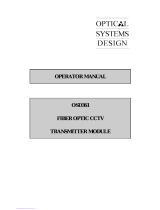
2. Press and hold the two retention buttons on each side of the camera module and then
pull off the covert liner. See Figure 2.1 below.
Removing the covert liner provides access to the menu keys, and the pan and tilt thumbscrew
adjustment locks. See Figure 3.1 on page 4.
Fig. 2.1 100 Series Camera Module
Covert Liner
Retention
Buttons (2)
Menu Keyboard
Monitor Jack
FRONT VIEW
BACK VIEW
Retention
Button (2)
Back View
Menu Keyboard
Monitor Jack
Front View
Covert Liner

4en | Positioning the Camera AutoDome Modular Camera System
F01U028033 | 2.0 | 2007.03 VG4-100 Series User’s Manual Bosch Security Systems, Inc.
3 Positioning the Camera
The camera module position can be adjusted along the horizontal, vertical, and diagonal (for
azimuth) axes. When adjusting the position, ensure that the picture displayed on the monitor
is level. After the covert liner is removed, position the camera by performing the following
steps:
1. For horizontal (pan) adjustment, loosen the thumbscrew at the platform base and rotate
the camera (left or right) to the desired position. The camera can be rotated up to 360º
between stops. If it hits the stop before achieving the desired position, rotate it in the
opposite direction. Retighten the thumbscrew to secure the camera.
2. For vertical adjustment (tilt), loosen the thumbscrew at the tilt wheel and position the
camera (up or down) to the desired position. The camera can be tilted up to 110º
between stops. Retighten the thumbscrew to secure the camera.
3. To compensate for angled ceilings or sidewall mounts, push the camera inward toward
its base and rotate it until the image on the monitor is horizontal. The camera can be
rotated up to 300º between stops.
Fig. 3.1 Camera Position Adjustments
!
WARNING! To prevent damage to the camera module do not rotate the camera past its stops.
!
CAUTION! The CCD image sensors are highly sensitive and require special care for proper
performance and extended lifetime. Do not expose it to direct sunlight or bright spotlights in
operating and non-operation conditions. Avoid bright lights in the field of view of the camera.
(2)
Tilt Wheel
Thumbscrew
(1)
Horizontal (pan)
Thumbscrew
Camera Module
Lock Tab
(3)
Diagonal Adj.
Camera Module
Lock Tab (1)
Horizontal (pan)
Thumbscrew
(2)
Tilt Wheel
Thumbscrew
(3)
Diagonal Adj.

AutoDome Modular Camera System Adjusting Focal Length (Zoom) and Focus | en 5
Bosch Security Systems, Inc. VG4-100 Series User’s Manual F01U028033 | 2.0 | 2007.03
4 Adjusting Focal Length (Zoom) and Focus
To adjust the camera lens focal length and focus, perform the following steps:
1. Select Set Focus Now from the Install menu.
2. To adjust the focal length, loosen the focal (zoom) lock screw and rotate the lens mecha-
nism (WIDE or TELE.) until you achieve the desired field of view. See Figure 4.1below.
3. To focus the image on the monitor, loosen the focus lock screw and turn the lens mecha-
nism (NEAR or FAR) until the image is in focus.
4. Repeat both these adjustments until the desired view is in focus.
5. Tighten both adjustment screws.
6. Exit the Install menu.
7. Remove the monitor jack and replace the covert liner and dome bubble when finished.
Fig. 4.1 Focus and Zoom Adjustment
5Advanced Setup
The VG4-100 Series camera module normally provides an optimal picture without the need for
further adjustments. Advanced setup options, however, are available for obtaining the best
results from the camera under special circumstances. There are two upper level On-Screen
Display (OSD) menus: the Main menu and the Install menu.
The Main menu allows you to select and setup the picture enhancement functions. The Install
menu allows you to set the camera ID, focus and synchronization settings. The Main and
Install menus have settings that you can select directly or open to submenus for a more
detailed setup.
Focus & Zoom
Lock Screws
Focus and Zoom
Lock Screws
i
NOTICE! Active menu selections can vary depending or the combination of camera, CPU and
COMM (communication) modules used. The menu selections described in this manual are
typical for a VG4-100 Series system.

6en | Advanced Setup AutoDome Modular Camera System
F01U028033 | 2.0 | 2007.03 VG4-100 Series User’s Manual Bosch Security Systems, Inc.
5.1 Accessing and Navigating Menus
There are five (5) keys used for navigating through the various menus. To access the setup
menus, press the center Select key to open and display the Main menu. Use the four direc-
tional keys to navigate through the menus.
Fig. 5.1 Menu Keyboard and Monitor Jack
Use the menu keys to perform the following:
– To access the Main menu or to select a sub-menu item, press the center Menu Select
key.
–To open the Install menu press the Menu Select key for approximately 1.5 seconds.
– To scroll up or down a menu press the Up or Down keys.
– To move through options or to set parameters, press the Left or Right keys.
The VG4-100 Series also supports a variety of remote methods to make camera adjustments,
including the following:
– A Universal keyboard using Bilinx over coax or UTP. For example, using a Bosch DiBos 8,
a Bilinx capable DIVAR, or an Allegiant system.
– A PC running the optional Bosch Configuration Tool for Imaging Devices (CTFID) software
with a USB Bilinx adapter (Part No. VP-CFGSFT).
– A PC connected to a TCP/IP network with an optional AutoDome IP module installed.
Menu Keyboard
UP
DOWN
RIGHT
LEFT
SELECT
Monitor Jack
Menu Keyboard
Monitor Jack
i
NOTICE! To restore a selected menu item to its factory default, quickly press the Menu
Select key twice.
To exit the OSD menus from any menu item, hold down the Menu Select key until the OSD
disappears.
i
NOTICE! To prevent unauthorized changes to the camera settings, the camera menu buttons
can be disabled using Bilinx communication through the CTFID software. Select the OnLine
Config button, then select the Miscellaneous branch and set Camera Buttons to Disable.

AutoDome Modular Camera System Advanced Setup | en 7
Bosch Security Systems, Inc. VG4-100 Series User’s Manual F01U028033 | 2.0 | 2007.03
5.2 Main Menu Functions
This section provides a graphical representation of the Main menu and descriptions for all
functions.
1 Available in Day/Night version cameras only, other versions show NightSense.
2 Only available when White Balance is set to Manual mode.
MAIN Menu
ALC ALC
ENHANCE ALC LEVEL
COLOR SHUTGAIN SHUTGAIN
BLC PEAK AVERAGE SHUTTER
EXIT ALC SPEED DEFSHUT
EXIT SENSUP
GAIN
ENHANCED MAXGAIN
AUTO BLACK DAY/NIGHT1DAY/NIGHT
SHARPNESS EXIT DAY/NIGHT
DNR SWITCH LVL
XF-DYN PRIORITY
EXIT IR CONTRAST
MONO BURST
COLOR EXIT
WHITE BALANCE
WB SPEED
RED (GAIN)
GREEN2
BLUE (GAIN)
SAT
EXIT
BLC
BLC
BLC LEVEL
BLC AREA AREA
EXIT

8en | Advanced Setup AutoDome Modular Camera System
F01U028033 | 2.0 | 2007.03 VG4-100 Series User’s Manual Bosch Security Systems, Inc.
MAIN Menu
ALC Submenu
ALC>SHUTGAIN Submenu
Function Selection(s) Description
ALC Selects submenu Accesses the Auto Level Control menu.
ENHANCE Selects submenu Accesses the Picture Enhancement menu.
COLOR Selects submenu Accesses the Color Control menu.
BLC ON, OFF,
or selects submenu
–Enables Back Light Compensation (BLC).
– Accesses the BLC submenu.
EXIT Exits this menu.
Function Selection(s) Description
ALC LEVEL (-15 to +15) Adjusts the video output level.
SHUTGAIN Selects submenu Accesses the Shutter and Gain control menu.
PEAK AVERAGE (-15 to +15) Adjusts the balance between peak and average
video control.
ALC SPEED Slow, Medium, Fast Adjusts the speed of the video level control loop.
EXIT Returns to the MAIN menu.
Function Selection(s) Description
SHUTTER AES, FL, FIXED – AES (Auto Electronic Shutter): The camera
automatically sets the optimum shutter
speed.
–FL (Flickerless): Avoids interference from
light sources.
–FIXED: Allows the user to define the shutter
speed.
DEFSHUT 1/60 (1/50), 1/100,
1/120, 1/250, 1/500,
1/1000, 1/2000, 1/5000,
1/10K
The camera tries to maintain the selected shutter
speed as long as the light level of the scene per-
mits.
(Only available if SHUTTER is set to AES mode.)
FIXSHUT 1/60 (1/50), 1/100,
1/120, 1/250, 1/500,
1/1000, 1/2000, 1/5000,
1/10K
Selects the shutter speed.
(Only available if SHUTTER is set to FIXED
mode.)
SENSUP OFF or (2x to 10x) Selects the sensitivity factor the camera is set to.
(Only available if SHUTTER is set to AES mode.)
GAIN AGC, FIXED – AGC mode: The camera automatically sets
the gain to the lowest possible value needed
to maintain a good picture.
–FIXED mode: The gain is set at a predefined
value.
MAXGAIN (0 to 26) Selects the maximum value the gain can have
during AGC operation.
FIXGAIN (0 to 26) Selects the gain setting.
(Only available if GAIN is set to FIXED mode.)

AutoDome Modular Camera System Advanced Setup | en 9
Bosch Security Systems, Inc. VG4-100 Series User’s Manual F01U028033 | 2.0 | 2007.03
3 Only available in Day/Night version cameras, color versions show NightSense.
ALC > SHUTGAIN > DAY/NIGHT Submenu
DAY/NIGHT3Selects submenu Accesses the Day/Night Control menu.
NIGHTSENSE AUTO, OFF, FORCED – AUTO mode: Camera automatically switches
to NIGHTSENSE in low light conditions.
–OFF mode: NIGHTSENSE is turned off.
–FORCED mode: The camera is set to NIGHT-
SENSE (black and white) mode
EXIT Returns to the ALC menu.
Function Selection(s) Description
i
NOTICE! If SensUp is active, some noise or spots may appear in the picture. This behavior is
normal. SensUp may cause some motion blur on moving objects.
Depending on the camera GAIN setting, unrelated menu items are not active.
Function Selection(s) Description
DAY/NIGHT AUTO, COLOR, MONO – AUTO: Switches the filter between COLOR
and MONO depending on the scene illumina-
tion level.
–COLOR: Use for normal daylight conditions.
–MONO: Removes the IR filter, providing full
IR sensitivity.
SWITCH LEVEL (-15 to +15) Sets the video leveling threshold when the cam-
era switches to monochrome operation.
PRIORITY COLOR, MOTION In AUTO mode:
–COLOR: Displays a color image as long as
the light level permits.
–MOTION: Avoids motion blur as long as the
light level permits.
IR CONTRAST NORMAL, ENHANCED – NORMAL: Optimizes contrast in mono-
chrome applications with visible light illumi-
nation.
–ENHANCED: Optimizes contrast in applica-
tions with high IR illumination levels.
MONO BURST ON, OFF – ON: The color burst remains active, even in
Monochrome mode.
–OFF: The color burst in the video signal is
switched OFF in Monochrome mode.
EXIT Returns to the SHUTGAIN menu.
i
NOTICE! Depending on the camera’s DAY/NIGHT setting, unrelated menu items are not active.

10 en | Advanced Setup AutoDome Modular Camera System
F01U028033 | 2.0 | 2007.03 VG4-100 Series User’s Manual Bosch Security Systems, Inc.
ENHANCED Submenu
COLOR Submenu
Function Selection(s) Description
AUTO BLACK ON, OFF ON: Automatically increases the visibility of
details.
SHARPNESS (-15 to +15) Adjusts the sharpness of the picture. Zero (0) is
the default position.
DNR
(dynamic noise
reduction)
AUTO, OFF AUTO: Automatically reduces the noise in the
picture. This option may cause some motion blur
with moving objects.
OFF: DNR is turned off.
XF-DYN OFF, LOW, MID, HIGH XF-DYN mode: Automatically optimizes picture
contrast.
EXIT Returns to the MAIN menu.
Function Selection(s) Description
WHITE BALANCE ATW, AWB HOLD,
MANUAL
–ATW (Automatic White Balance): Allows the
camera to constantly adjust for optimal
color reproduction.
–AWB HOLD: Puts the ATW on hold and
saves the color settings.
–MANUAL: Allows the red, green and blue
gain to be set manually to a desired posi-
tion.
WB SPEED Slow, Medium, Fast Adjusts the speed of the white balance control
loop when in ATW mode.
RED-GAIN
RED
(-5 to +5)
(-30 to +30)
– In ATW mode: Adjusts the red gain to opti-
mize white.
– In Manual mode: Adjusts red gain.
GREEN (-5 to +5) In Manual mode: Adjusts the green gain.
(Not available in ATW mode.)
BLUE-GAIN
BLUE
(-5 to +5)
(-30 to +30)
–In ATW mode: Adjusts the blue gain to opti-
mize white.
– In Manual mode: Adjusts the blue gain.
SAT (-15 to +5) Adjusts the color saturation.
(-15 produces a monochrome picture.)
EXIT Returns to the MAIN menu.

AutoDome Modular Camera System Advanced Setup | en 11
Bosch Security Systems, Inc. VG4-100 Series User’s Manual F01U028033 | 2.0 | 2007.03
Back Light Compensation (BLC) Submenu
Function Selection(s) Description
BLC ON, OFF ON: The video level optimizes the selected area
of the image. Parts outside this area may be
underexposed or overexposed, which is normal.
BLC LEVEL (-15 to +15) Adjusts the balance between the selected BLC
area and its surroundings.
BLC AREA Selects submenu Accesses the Back Light Compensation area
menu.
To size the BLC area:
1. Select the AREA option from the BLC menu.
The monitor displays the current area with
the upper left corner flashing.
2. Move the flashing corner of the image by
using the Up, Down, Left and Right keys
to change the size and shape of the area.
3. Press the center Menu Select key to move
the flashing cursor to the opposite (or diag-
onal) corner, which can now be used to
change the size and shape of the area.
4. Press the Menu Select key again to save
the area and to exit the AREA menu.
EXIT Returns to the MAIN menu.

12 en | Advanced Setup AutoDome Modular Camera System
F01U028033 | 2.0 | 2007.03 VG4-100 Series User’s Manual Bosch Security Systems, Inc.
5.3 Install Menu Functions
This section provides a graphical representation of the Install menu and descriptions for all
functions.
Install Menu
INSTALL Menu
INSTALL Menu
CAMERA ID
SET FOCUS NOW INSTALL CAMERA ID
COMM CAMERA ID
SYNC ID POSITION
DEFAULTS EXIT
EXIT
INSTALL SYNC
SYNC
VPHASE
EXIT
INSTALL DEFAULTS
RESTORE ALL?
EXIT
Function Selection(s) Description
CAMERA ID Selects submenu Accesses the Camera ID submenu.
SET FOCUS NOW Completely opens the lens iris for best focus.
The recommended focus procedure is:
1. Unlock the focus locking screw.
2. From the INSTALL menu highlight SET
FOCUS NOW.
3. Turn the lens focus adjustment as required.
4. Tighten the lens focus locking screw.
5. Exit the menu selection.
COMM ON, OFF Turns on Bilinx communication. See notice
below.
SYNC Selects submenu Accesses the synchronization functions.
DEFAULTS Selects submenu Returns all settings for all modes to their
default.
EXIT Exits this menu.
i
NOTICE! When using Bilinx control, the COMM ON/OFF menu selection is not active. This
function can be accessed only through the camera menu keys when the CTFID software is not
actively running.

AutoDome Modular Camera System Advanced Setup | en 13
Bosch Security Systems, Inc. VG4-100 Series User’s Manual F01U028033 | 2.0 | 2007.03
CAMERA ID Submenu
SYNC Submenu
DEFAULTS Submenu
Function Selection(s) Description
CAMERA ID Selects submenu To enter up to a 17-character camera name:
1. Press the Menu Select key to enter the
Camera ID string.
2. Enter up to a 17-character string name for
the camera.
3. Use the Up and Down keys to select a charac-
ter.
4. Use the Left and Right keys to change
position in the string.
5. Press the Menu Select key to save and to
exit the character string.
6. Exit the Camera ID menu.
ID POS OFF, TOP, BOT Use left or right keys to select:
OFF: Camera ID not displayed.
TOP: Camera ID displayed at upper left corner of
display.
BOT: Camera ID displayed at lower left corner of
display.
(The camera ID is not displayed when the OSD
menu is open.)
EXIT Returns to the INSTALL menu.
Function Selection(s) Description
SYNC INTERNAL, LINE LOCK INTERNAL: Synchronizes the camera to an inter-
nal crystal. (default)
LINE LOCK: Synchronizes the camera to AC
power and eliminates picture roll in multi-camera
systems.
VPHASE (0º to 358º) Adjusts the vertical phase offset in LINE LOCK
mode.
(Only active if a valid power supply frequency is
detected.)
Exit Returns to the INSTALL menu.
Function Selection(s) Description
RESTORE ALL? NO, YES Use the left or right keys to select:
NO: To not change settings.
YES: To restore all defaults. You receive a confir-
mation message.
Exit Returns to the INSTALL menu.

14 en | Configuring the VG4-100 Series IP AutoDome AutoDome Modular Camera System
F01U028033 | 2.0 | 2007.03 VG4-100 Series User’s Manual Bosch Security Systems, Inc.
6 Configuring the VG4-100 Series IP AutoDome
The VG4-100 Series AutoDome can be ordered with an optional IP module that allows the
AutoDome to transmit images over a TCP/IP network. It also allows users to configure the
camera display settings, camera operating settings, and to configure the network parameters.
The VG4-100 Series IP AutoDome incorporates a network video server in the IP module. The
primary function of the server is to encode video (and control data) for transmission over a
TCP/IP network. With its MPEG-4 encoding, it is ideally suited for IP communication and for
remote access to digital video recorders and multiplexers. The use of existing networks means
that integration with CCTV systems or local networks can be achieved quickly and easily.
Video images from a single camera can be simultaneously received on several receivers.
6.1 Overview of Functions
The IP module adds the following functionality to a VG4-100 Series system:
Function Description
Receiver You can use an MPEG-4 compatible hardware decoder (for example
the VIP XD) as a receiver. Computers with decoding software such
as VIDOS or computers with the Microsoft Internet Explorer Web
browser installed can also receive video images.
Video encoding The camera uses the MPEG-4 compression standard and ensures
that the data rate remains low even with high image quality and can
also be adapted to local conditions within wide limits.
Dual Streaming Encodes dual data streams simultaneously according to two individ-
ually customized profiles. This feature creates two (2) data streams
per camera that can serve different purposes. For example, one (1)
data stream for local recording and one (1) data stream optimized
for transmission over the Local Area Network (LAN).
Multicast Enables simultaneous, real-time transmission to multiple receivers.
The network must implement the UDP and IGMP V2 protocols as a
prerequisite for Multicasting.
Configuration You can configure all camera settings from a Web browser con-
nected to the local network (Intranet) or connected to the Internet.
You can also update the firmware, load device configurations, store
configuration settings, and copy these settings from one camera to
another.
Snapshots Allows you to take and store individual video frames as JPEG images
from the Web browser interface.
Backup You can save video images as a file on a computer’s hard drive from
the Web browser interface.

AutoDome Modular Camera System Configuring the VG4-100 Series IP AutoDome | en 15
Bosch Security Systems, Inc. VG4-100 Series User’s Manual F01U028033 | 2.0 | 2007.03
6.2 System Requirements
The VG4-100 Series IP AutoDome requires specific software or hardware to allow a user to
view live images and to configure camera settings over a TCP/IP network. These requirements
are:
– A computer with the Microsoft Windows 2000 or XP operating system, network access,
and the Microsoft Internet Explorer Web browser version 6.0 or later, or
– A computer with Microsoft Windows 2000 or XP operating system, network access, and
reception software such as the Bosch VIDOS software or Bosch Dibos 8.0. (See
www.boschsecurity.com for more information about Bosch software and hardware for IP
cameras), or
– An MPEG-4 compatible hardware decoder from Bosch Security Systems (such as the VIP
XD) as a receiver and a connected video monitor. (See www.boschsecurity.com for more
information about Bosch software and hardware for IP cameras).
If you choose to use a computer running Microsoft Internet Explorer or any of the Bosch soft-
ware, the computer must conform to the following minimum requirements:
– Processor: 1.8 GHz Pentium IV
– RAM: 256 MB
– Video system: 128 MB video memory, 1024x768 display with a minimum of 16-bit color
– Network interface: 100-BaseT
–DirectX: 9.0c
– Microsoft Internet Explorer, version 6.0 or higher
– Bosch MPEG ActiveX utility
– Java Virtual Machine (supplied)
6.3 Connecting the IP AutoDome to the PC
1. Install the IP AutoDome according to the instructions in the Modular AutoDome Camera
System Installation Manual.
2. Connect an Ethernet cable from the IP AutoDome RJ45 connector to a dedicated network
switch to bypass the Local Area Network (LAN).
3. Connect the dedicated network switch to the RJ45 connector on the PC . (See option A
below.)
i
NOTICE! Ensure that the graphics card is set to 16-bit or 32-bit color. If you need further
assistance, contact your PC system administrator.
i
NOTICE! The IP AutoDome can also be connected directly to a PC using an Ethernet crossover
cable with RJ45 connectors. (See option B below.)

16 en | Configuring the VG4-100 Series IP AutoDome AutoDome Modular Camera System
F01U028033 | 2.0 | 2007.03 VG4-100 Series User’s Manual Bosch Security Systems, Inc.
Fig. 6.1 AutoDome IP System Configuration
6.4 Configuring the IP Camera
To operate the camera in your network you must assign it a valid network IP address. The
default IP address is 192.168.0.1, but you may have to change this address if it conflicts with
another device on your network.
To properly configure the camera for your network, you need the following information:
– Unit IP address: An identifier for the camera on a TCP/IP network. For example,
140.10.2.110 is a valid syntax for an IP address.
– Subnet mask: A mask used to determine what subnet an IP address belongs to.
– Gateway IP address: A node on a network that serves as an entrance to another network.
– Port: An endpoint to a logical connection in TCP/IP and UDP networks. The port number
identifies the use of the port for use through a firewall connection.
The IP AutoDome defaults are as follows:
– IP Address: 192.168.0.1
– Subnet Mask: 255.255. 255.0
– Gateway IP Address: 0.0.0.0
6.4.1 Installing the Required Software
To view live video, you must install Bosch MPEG ActiveX, DirectX, and Java Virtual Machine.
To install the software do the following:
1. Insert the IP AutoDome software CD into the CD-ROM drive of the computer.
2. Click the Windows Start button, select Run, and then Browse to the CD drive.
3. Open the Install folder, then the MPEG_ActiveX folder and double click on the MPE-
GAx.exe file. Follow the on-screen instructions to install the Bosch MPEG ActiveX.
4. Open the Tools folder, the DirectX9 folder, and then the DirectX9.0c folder and dou-
ble-click on the dxsetup.exe file. Follow the on-screen instructions to install DirectX.
5. Open the Tools folder, then the Java VM folder and double click on the executable file.
Follow the on-screen instructions to install Java.
PC
IPIP
Net Switch
AutoDome
PC
IP
AutoDome
A
B
i
NOTICE! Ensure that the network parameters of your cameras are available before you begin
configuration.
/