
Model:

1 Series
Model:

2
Model:
1
2
3-4
5-6
7-8
9
10
10-11
11
12
13
14-15
16
17
18-19
20
21-22
23
Product Image
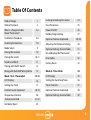
Table of Contents
What is a Programmable
Room Thermostat?
Installation Procedure
Installing the batteries
Mode Select
Pairing the neoHub
Pairing the neoAir
NeoAir and Mesh
Pairing with the RF-Switch
Pairing with the UH8-RF Wiring Centre
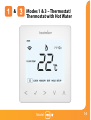
Mode 1 & 3 - Thermostat
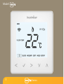
LCD Display
Setting the Clock
Comfort Levels Explained
Temperature Control
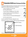
Temperature Hold
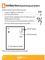
Hot Water Boost
24
25
26
27
28-29
30
31
32
32
33
34
35
36
37
38
39
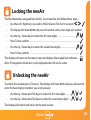
Locking/Unlocking the neoAir
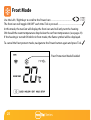
Frost Protection
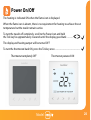
Power ON/OFF
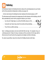
Holiday Programming
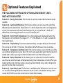
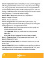
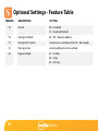
Optional Features Explained
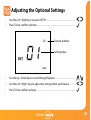
Adjusting the Optional Settings
Optional Settings Feature Table
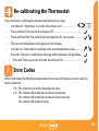
Re-calibrating the Thermostat
Error Codes
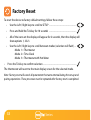
Factory Reset
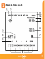
Mode 2 - Time Clock
LCD Display
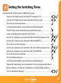
Setting the Switching Times
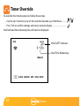
Timer Override
Optional Features Explained
Optional Settings Feature Table
Table Of Contents

3 Series
Section Header
What is a Programmable Room Thermostat?
A programmable room thermostat is both a programmer and a room thermostat.
A programmer allows you to set “On” and “Off” periods to suit your own lifestyle.
A room thermostat works by sensing the air temperature, switching on the heating
when the air temperature falls below the thermostat setting, and switching it off once
this set temperature has been reached.
So a programmable room thermostat lets you choose what times you want the heating
to be on, and what temperature it should reach while it is on. It will allow you to select
different temperatures in your home at different times of the day (and days of the week)
to meet your particular needs and preferences.
Setting a programmable room thermostat to a higher temperature will not make the
room heat up any faster. How quickly the room heats up depends on the design and
size of the heating system.
Similarly reducing the temperature setting does not affect how quickly the room cools
down. Setting a programmable room thermostat to a lower temperature will result in
the room being controlled at a lower temperature, and saves energy.

Section Header
4
Model:
The way to set and use your programmable room thermostat is to find the lowest
temperature settings that you are comfortable with at the different times you have
chosen, and then leave it alone to do its job.
The best way to do this is to set the room thermostat to a low temperature
– say 18°C , and then turn it up by 1°C each day until you are comfortable with the
temperature. You won’t have to adjust the thermostat further. Any adjustment above
this setting will waste energy and cost you more money.
You are able to temporarily adjust the heating program by overriding or using the
temperature hold feature. These features are explained further on pages 17 and 18
of this manual.
Programmable room thermostats need a free flow of air to sense the temperature,
so they must not be covered by curtains or blocked by furniture. Nearby electric
fires, televisions, wall or table lamps may also prevent the thermostat from working
properly.

5 Series
Section Header
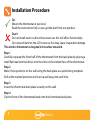
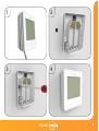
Installation Procedure
This wireless thermostat is designed to be surface mounted.
Step 1
Carefully separate the front half of the thermostat from the back plate by placing a
small flat head terminal driver into the slots on the bottom face of the thermostat.
Step 2
Mark 2 hole positions on the wall using the back plate as a positioning template.
Drill at the marked positions and insert a wall plug into each hole.
Step 3
Screw the thermostat back plate securely on the wall.
Step 4
Clip the front of the thermostat back onto the thermostat back plate.
Do
Mount the thermostat at eye level.
Read the instructions fully so you get the best from our product.
Don’t
Do not install near to a direct heat source as this will affect functionality.
Do not push hard on the LCD screen as this may cause irreparable damage.

Section Header
6
Model:
1 2
3 4

7 Series
Section Header
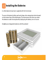
Installing the Batteries
4 x AAA batteries have been supplied with this thermostat.
To access the battery holder, push and release the compartment door located
on the bottom face of the thermostat. The thermostat will inform you when
the batteries need to be replaced by displaying the battery icon on screen.
Do not use rechargeable batteries with this product!

Section Header
8
Model:
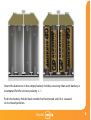
Insert the batteries in the empty battery holder, ensuring that each battery is
orientated for the correct polarity + / -.
Push the battery holder back inside the thermostat until it is secured
in its closed position.

9 Series
Section Header
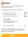
The neoAir can either be used as a Thermostat, standalone Time Clock, or
combined Thermostat and Time clock.
To change between thermostat or time clock modes, follow these steps.
• Use the Left / Right keys to scroll to SETUP ................................................................
• Press and hold the Tick button for 10 seconds .........................................................
• Use the Left / Right keys to scroll between modes .................................................
Mode 1 = Thermostat
Mode 2 = Time Clock
Mode 3 = Combined Thermostat & Time Clock
Note: the selected option will flash.
• Press the Tick key to confirm selection ........................................................................
The neoAir will revert to the main display screen for the selected mode.
For time clock mode instructions, first pair the time clock with the neoHub as
explained on page 10, then turn to page 34.
Mode Select

Section Header
10
Model:
The next step is to join the neoAir to the neoHub. We recommend joining any wired neoStat
or neoPlug (if used) to the neoHub first. This will help to extend the wireless network for areas
where radio signals are problematic.
To add a neoAir, follow these steps;
• Select Add Zone, enter a zone title and press Add Zone again.
• You now have two minutes to join the neoAir to the neoHub.
• On the neoAir, use the Left / Right keys to select SETUP and press Tick ...............
• Feature 01 is displayed on screen.
Pairing the neoAir
Pairing the neoHub
To pair the neoHub with the neoApp, follow these steps.
• Connect the power supply to the neoHub.
• Connect the neoHub to your router with the Ethernet cable provided. The router will
automatically assign an IP address to the neoHub, the Link LED will light up once the
neoHub has connected to your network.
• Connect your smartphone or tablet device to the same WiFi network as your router.
• Download the FREE Heatmiser neoApp from the Apple App Store, Google Play Store,
Amazon App Store or Windows Phone App Store and register an account.
• Once you have registered your account, press the Login button then press the
Add Location option.
• Press the connect button on the neoHub to add the location to your account.
• When successfully connected, enter a title for the new location (e.g. Home) and
configure the time zone for the system.

11 Series
Section Header
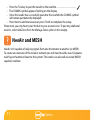
NeoAir isn’t capable of relaying signals from one thermostat to another (or MESH).
To create an extension of the wireless network you will need to add a neo-X repeater,
neoPlug or Heatmiser Boost to the system. The neoAir can also talk via wired (MESH
capable) neoStats.
NeoAir and MESH
• Press the Tick key to pair the neoAir to the neoHub ...........................................
• The COMMS symbol appears flashing on the display.
• Once the neoAir has successfully paired to the neoHub the COMMS symbol
will remain permanently displayed.
• Press Next to add more zones or press Finish to complete the setup.
Please note, you only have to pair the hub to your account once. To pair any additional
neoAir’s, select Add Zones from the Manage Zones option in the neoApp.

Section Header
12
Model:
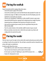
Pairing With the RF-Switch
• Use the Left/Right arrow keys to scroll to SETUP and press Tick key once ................
• The display will show 01 in the top right hand corner.
• Press the Down arrow key once. The display will now show P1 .....................................................
• Press Tick again to start 99 second countdown .....................................................................................
• During the countdown press and hold either ‘Boiler’ or ‘CH1’ pairing buttons on the RF-
Switch for 5 seconds.
Boiler = When wiring to terminal marked ‘SL’ & ‘LR’
CH1 = When wiring to terminals marked ‘COM1’ & ‘NO1’
The LED on the RF-Switch will flash to indicate it’s in pairing mode. Once paired the LED will
stop flashing.

13 Series
Section Header
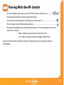
Pairing With the UH8-RF Wiring Centre
On the UH8-RF, take note of the numbers set on the rotary switches (UH8-RF ID numbers
01-99).
Each UH8-RF on the system needs to have a different ID number.
Set your first UH8-RF to 01
At the thermostat:
• Use the Left/Right arrow keys to scroll to SETUP and press tick key once ...............
• The display will now show 01 in the top right hand corner.
• Press the Down key twice so that P2 shows on the display .........................................................
• Press Tick once ...................................................................................................................................................
• Use the Left/Right arrow keys to set the large digits to the board address of the UH8-RF.
This is the number set on the UH8-RF rotary switches ...........................................................
(You must set a unique board address for each UH8-RF installed).
• Press Tick once. Small digits in the top right hand corner of the display will
now flash ..............................................................................................................................................................
• The UH8-RF is an 8 zone receiver. Use the Up/Down buttons to select the zone
this thermostat should be linked to ...............................................................................................
• Press Tick to select zone type (Radiators or Underfloor Heating) ..............................................
• Use the Up/Down buttons to select either: RA = Radiators or
UF = Underfloor Heating .....................................................................................................................
• Press Tick to finish and confirm settings. Display will return to the main screen ...............
Example: Rotary Switch showing ID No. 99.

Section Header
14
Model:
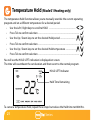
& Modes 1 & 3 – Thermostat/
Thermostat with Hot Water

15 Series
Section Header
1 3
14
15
16
2
5
6
7
4
8
9
13
12
10
11
FLOOR TEMP
ROOM TEMP

Section Header
16
Model:
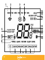
1. Day Indicator - Displays the day of the week.
2. Comms Symbol - Displayed when connected to the neoHub.
3. Frost Symbol - Displayed when frost protection mode is active.
4. Flame Symbol - Displayed when the thermostat is calling for heat, flashes when
optimum start is active.
5. Floor/Room Temp – Indicates the current sensor mode.
6. Set - Displayed when changes are being made to the program schedule or
current set point.
7. Key Lock Indicator – Displayed when the KeyLock is Locked.
8. Program Indicator – Displayed during programming to show which period
is being altered.
9. Main Menu – Displays which option is currently selected.
10. Battery Indicator – Shown when batteries need replacing.
11. Timer Status – Displays the current state of the timed output.
12. Temperature Format - Degrees Celsius or Fahrenheit.
13. Temperature – Displays the current sensor temperature.
14. Clock - Time displayed in 24 hour format.
15. Holiday Left – Displayed when the thermostat is in holiday mode.
16. Hold Left – Displayed when a temperature hold is active, the remaining time
will be shown.
LCD Display

17 Series
Section Header
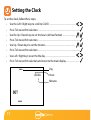
Setting the Clock
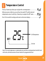
To set the clock, follow these steps.
• Use the Left / Right keys to scroll to CLOCK ........................................................
• Press Tick to confirm selection ..........................................................................................
• Use the Up / Down keys to set the hours (24 hour format) ...........................
• Press Tick to confirm selection ..........................................................................................
• Use Up / Down keys to set the minutes ...............................................................
• Press Tick to confirm selection ..........................................................................................
• Use Left / Right keys to set the the day ................................................................
• Press Tick to confirm selection and return to the main display ...........................
Day
Minutes
Hours

Section Header
18
Model:
Comfort Levels Explained
The neoAir offers three program mode options; Weekday/Weekend programming,
7 Day programming and 24 Hour programming. There is also the option to
use the thermostat as a Non-Programmable thermostat.
When thermostats are connected to a network, the program mode for the system is
configured by using the neoApp.
The thermostat is supplied with comfort levels already programmed, but these can be
changed easily. The default times and temperature settings are;
07:00 - 21°C (Wake) 09:00 - 16°C (Leave) 16:00 - 21°C (Return) 22:00 - 16°C (Sleep)
If you only want to use 2 levels, you should program the unused levels to --:--
For Weekday/Weekend programming, the four comfort levels are the same for Mon-Fri, but can
be different for Sat-Sun. For 7 Day programming each day of the week can have four different
comfort levels. In 24 Hour mode all days are programmed with the same comfort levels.
• To program the comfort levels, use the Left / Right keys to scroll to EDIT .................
• Press Tick to confirm selection .....................................................................................................
• Use the Left / Right keys to select day / period of week (the selection will flash).
• Press Tick to confirm selection .....................................................................................................
• WAKE will now flash and the current time and temperature setting will be shown.
• Press Tick to alter WAKE settings ..................................................................................................

19 Series
Section Header
• Use the Up / Down keys to set the hours ..............................................................
• Press Tick to confirm .............................................................................................................
• Use the Up / Down keys to set the minutes .........................................................
• Press Tick to confirm .............................................................................................................
• Use the Up / Down keys to set the temperature ................................................
• Press Tick to confirm the settings ....................................................................................
• Press the right arrow key ....................................................................................................
• LEAVE will now flash and the current settings will be displayed.
• Press Tick to alter LEAVE settings .....................................................................................
• Repeat these steps to set all comfort levels.
• For any unused periods set time to --:--
• Use the Left / Right keys to scroll to DONE and press Tick .......................
Page is loading ...
Page is loading ...
Page is loading ...
Page is loading ...
Page is loading ...
Page is loading ...
Page is loading ...
Page is loading ...
Page is loading ...
Page is loading ...
Page is loading ...
Page is loading ...
Page is loading ...
Page is loading ...
Page is loading ...
Page is loading ...
Page is loading ...
Page is loading ...
Page is loading ...
Page is loading ...
Page is loading ...
Page is loading ...
Page is loading ...
Page is loading ...
-
 1
1
-
 2
2
-
 3
3
-
 4
4
-
 5
5
-
 6
6
-
 7
7
-
 8
8
-
 9
9
-
 10
10
-
 11
11
-
 12
12
-
 13
13
-
 14
14
-
 15
15
-
 16
16
-
 17
17
-
 18
18
-
 19
19
-
 20
20
-
 21
21
-
 22
22
-
 23
23
-
 24
24
-
 25
25
-
 26
26
-
 27
27
-
 28
28
-
 29
29
-
 30
30
-
 31
31
-
 32
32
-
 33
33
-
 34
34
-
 35
35
-
 36
36
-
 37
37
-
 38
38
-
 39
39
-
 40
40
-
 41
41
-
 42
42
-
 43
43
-
 44
44


Ask a question and I''ll find the answer in the document
Finding information in a document is now easier with AI
Related papers
-
Heatmiser Touch-RF User manual
-
Heatmiser Slimline-RF V3 Operating instructions
-
-
Heatmiser UH8-RF User manual
-
-
-
-
-
-
Other documents
-
 PW maintenance DT-NTS Operating Instructions Manual
-
 flowkey HY02TP Wi-Fi Plug In Thermostat User manual
-
Roma Heating CT1000 User manual
-
Roma Heating RT5 Operating instructions
-
 PlumbNation JG STATPLUS/TS/V3 Operating Instructions Manual
-
Timeguard TRT037N User manual
-
BECA BHT-12 User manual
-
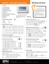 EPH Controls Vision33R47-RF 4 Zone RF Programmer User manual
-
Timeguard TRT034N Operating instructions
-
COLDBUSTER MWD5 User manual


