Page is loading ...

SYSCROLL 20-30 AIR EVO
Air Cooled Inverter Driven Water Heat Pump
Engineering Data Manual
Chiller
20.0 to 34.0 kW
20.0 to 35.0 kW


SYSCROLL 20-30 AIR EVO |3
Wide load variation capability.
Cooling operation → down to 30 % and up to 140%
of nominal capacity.
Heating operation → down to 40% and up to 130% of
nominal capacity.
Great accuracy in maintaining desired set-point.
Unit optimization for heating operation both for fan coil
and oor application.
Excellent efciency performances both at full and partial
load (EER/COP/SEER/SCOP).
Wide operating limits in heating mode:
Min outdoor ambient temperature → -15 [°C].
Max leaving water temperature → 55 [°C].
Simple refrigerant circuit with easy access to inner com-
ponents for maintenance purpose.
Aeraulic independence between refrigerant circuit and
condensing side.
New fan motors (Erp 2015 compliant) with integrated
grill, nozzle and condensers.
Possibility to manage auxiliary heating source, second
set-point zone eld components
Key points
Several options / accessories provided with standard de-
livery:
Fan speed control → cooling operation with low OAT /
heating operation with high OAT.
Electronic expansion valve → precision in SH control.
ModBus interface → supervision ready.
Phase sequence control algorithm → safe electric in-
stallation.
Modulating capacity control → precision in water set-
point control.
Soft-start function → low inrush current.
Power factor correction function → low input current
distortion.
Coil blue n treatment → effective water drainage dur-
ing defrost.
Coil guard → protection during transport and installa-
tion.
Double set-point→ different daily proles.
Dynamic set-point → water prole in accordance with
outdoor air temperature or current / voltage signal.
Water lter → protection against impurities.
Water differential pressure switch → protection against
low water ow.
Rubber pads → basic vibration attenuation.
2,75
3,00
3,25
3,50
3,75
4,00
4,25
4,50
4,75
25% 50% 75% 100%
EER (kW/kW)
CAPACITY PART LOAD
FIXED SPEED VARIABLE SPEED
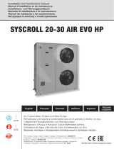
ESEER= 4,08 +20%
ESEER= 3,34
CAPACITY PART LOAD
25% 50% 75%
100%
COP (kW/kW)
2,25
2,50
3,25
3,00
2,75
+26%
+13%
+5%

| SYSCROLL 20-30 AIR EVO
4
Comparison between xed speed and variable
speed technology - Cooling operation
5
7
10
15
18
0
5
10
15
20
25
30
25
30
35
40
45
Cooling capacity (kW)
Nominal performance
LWT (°C)
5
7
10
15
18
0
5
10
15
25
30
35
40
45
Min performance
Cooling capacity (kW)
5
7
10
15
18
0
5
10
15
20
25
30
35
40
45
Nominal performance
Cooling capacity (kW)
5
7
10
15
18
0
5
10
15
20
25
30
35
40
45
25
30
35
40
45
Max performance
Cooling capacity (kW)
OAT (°C)
LWT (°C)
OAT (°C)
LWT (°C)
OAT (°C)
LWT (°C)
OAT (°C)

SYSCROLL 20-30 AIR EVO |5
Comparison between xed speed and variable
speed technology - Heating operation
50
45
40
35
0
5
10
15
12
7
2
-2
-7
Min performance
Heating capacity (kW)
50
45
40
35
0
5
15
10
20
25
12
7
2
-2
-7
Nominal performance
Heating capacity (kW)
50
45
40
35
0
5
10
15
20
25
30
35
12
7
2
-2
-7
Max performance
Cooling capacity (kW)
LWT (°C)
OAT (°C)
LWT (°C)
OAT (°C)
LWT (°C)
OAT (°C)
50
45
40
35
0
5
10
15
20
25
30
12
7
2
-2
-7
Heating capacity (kW)
Nominal performance
LWT (°C)
OAT (°C)
5
0
45
4
0
3
5
0
5
1
0
15
20
2
5
30
12
7
2
-2
7
LWT (°C)
OAT (°
C)
5
0
45
4
0
3
5
0
5
1
0
1
5
1
2
7
2
-2
LWT (°C)
OAT
(°
C)
50
45
40
35
0
5
10
1
5
20
25
30
35
12
7
2
-2
LWT (°C)
OAT (°C)

| SYSCROLL 20-30 AIR EVO
6
General
SYSCROLL AIR EVO air cooled water heat pumps have
been designed and optimized to operate with R410A re-
frigerant and inverter driven scroll compressors.
Thanks to inverter technology it is possible to cover with
only 2 sizes a very wide capacity range both in cooling
(from 20 to 35 kW) and heating (from 20 to 34 kW) op-
eration.
All units are equipped with a single inverter driven
3-phase scroll compressor.
The general operation status of the unit is steadily man-
aged by a microprocessor implementing a dedicated de-
veloped software, allowing operation with a very low wa-
ter content (2,5 l/kW) and ensuring a total protection of
compressor inside its operating envelope.
An external buffer tank can be supplied as accessory for
eld installation; it is mainly recommended to provide
compensation to water temperature decrease occurring
during defrost operation.
The units can be equipped with an optional inverter driv-
en multistage centrifugal pump.
Conformity with standards
The units are in conformity with the following standards:
Machinery Directive: 2006/42/EC
Electromagnetic Compatibility Directive: 2014/30/UE
Pressure Equipment Directive: 2014/68/UE
Ecodesign Directive: 2009/125/EC
Cabinet
The cabinet is made of heavy gauge galvanized steel.
All galvanized steel components are individually painted
by a special painting process before the assembly of the
unit. This painting system performs a homogeneous pro-
tection to the corrosion. The painting is a polyester pow-
der based type, coloured in RAL 7040 as standard. The
units are suitable for outdoor installation, directly on the
building roof or at the ground level.
Compressors
Compressors are hermetic scroll equipped with brushless
direct current motor (BLDC) type.
Motor is cooled down by refrigerant gas itself; a discharge
gas thermostat and a discharge temperature sensor pro-
tect motor against over-temperature operation.
A 40 W belt electric heater is switched ON during com-
pressor OFF time in order to protect against ooded starts.
Compressors are assembled on rubber shock absorbers to
limit vibrations transmission.
Evaporator
Indoor heat exchangers are brazed stainless steel plate
type. They are insulated with a 10 mm thick closed cell
polyethylene foam material and provided with male gas
threaded connections.
They are protected by a 35 W antifreeze electric heater to
ensure a good protection against freezing at low ambient
temperature when the unit is switched off.
Maximum working pressure is 10 bar at water side and 45
bar at refrigerant side.
Air cooled condenser coil
Outdoor heat exchanger is nned tube coil. Coils are built
with internally grooved copper tubes expanded into cor-
rugated aluminium ns. Fin pitch and blue n hydrophilic
treatment are intended to optimize coil behaviour during
heating and defrost operations.
Specications
Sy Scroll Air -
SIZES HP
-
EVO
HP = Heat Pump; Version - = BLN.

SYSCROLL 20-30 AIR EVO |7
Condenser fans
Units are equipped with two 500 mm diameter axial fans
with proled, sickle shaped blades designed with bioni-
cal know how, optimized full bellmouth with static blades
(motor suspension) and short diffusor.
They are placed directly in front of the coil in order to in-
crease the air ow and the heat transfer between air and
refrigerant.
Fan motors have IP54 protection grade, and thermostat
protection placed in the bearings. Both fans are equipped
with a safety grill.
Refrigerant circuit
Refrigerant circuit is equipped with one hermetic scroll
compressor, 4-way reversing valve, bi-ow lter drier,
sight glass, bi-ow electronic expansion valve, liquid re-
ceiver and suction accumulator.
Hydraulic circuit
The units can be equipped with an optional inverter driv-
en multi-stage centrifugal pump providing outdoor avail-
able static pressure. Pump impeller is insulated with anti-
condensation shell. Water lter is supplied as standard.
Safety valve and expansion tank are placed on suction
side of the pump. Water connections are 1” 1/4 male GAS
threaded type.
Control panel
A new optimized control with a simple user keyboard,
manage unit operation under different load and tempera-
ture condition and protect compressor against operation
out of its envelope.
In addition to standard features - as water temperature
control - the control can also manage following functions:
Dynamic set point with OAT compensation or current /
voltage input signal,
Double set point,
Advanced pump management,
Counting of pump / compressors operating hours,
Display of discharge and suction pressure values,
Display of temperature sensors,
History of stored alarms.
Safety and control devices
Each unit has complete with the following safety and con-
trol devices.
Safety
Fans motor overload protection,
Compressor motor overload protection,
Phase sequence control,
Pump motor overload protection,
High pressure switch,
Low pressure switch,
Discharge gas thermostat,
Evaporator antifreeze electric heater,
Crankcase oil electric heater.
Control
Return water temperature sensor,
Leaving water temperature sensor,
Coil temperature sensor,
Suction and discharge temperature sensors,
Air temperature sensor,
Suction and discharge pressure transducers.
Standard equipment
Fan speed control.
Electronic expansion valve.
ModBus protocol kit for BMS.
Phase sequence control function.
Modulating capacity control.
Coil blue n treatment.
Coil guard.
Double set-point.
Dynamic set-point.
Water lter.
Water differential pressure switch.
Evaporator antifreeze electric heater.
Compressor belt electric heater.
Factory-installed options
Inverter driven multistage centrifugal pump.
Field-installed accessories
Water buffer tank (112 l),
Water ow switch,
Water pressure switch,
In/out valve kit,
No pump kit,
Remote ON/OFF control
Auxiliary heater kit
Second set-point zone kit.

| SYSCROLL 20-30 AIR EVO
8
Accessories & Options
SYSCROLL AIR EVO Delivery Abbreviation Description & Benet
Phases sequence Std PHC It allows to check the correct sense R-S-T of electric supply phases
for 400/3/50 units.
Main switch Std Front operated switch-disconnector with direct mounted handle to
cut the power Supply Line according CE standards.
Differential pressure switch Std Prevents the operation of the unit if the circulating chilled uid is
insufcient, by checking water differential pressure.
Antifreeze electric heater kit Std EEH Electrical Heater protects the plate exchanger.
Low ambient kit
(pressostatic modulating fan speed control) Std FSC
Electronic speed controllers are designed to control the speed
of fan motors in Air Cooled Chiller and Heat pump. Fan Speed
controlled by Condensing Pressure in cool mode or by Air Temp in
heat mode. Using variable fan speed controllers offers following
benets in commercial refrigeration or air-conditioning applications:
High Efciency, Low Noise level, Low air temperature in cool mode
and High air temperature in heat mode.
Double set point Std DSP Can manage two different setpoints selected by remote dry
contact.
Electronic expansion valve Std EEV
It is the device able to control the refrigerant ow on suction line
trough a stepper motor in order to keep the superheat as constant
as possible.
Modbus protocol kit for BMS Std MBS It permits the integration of the unit with Modbus
protocol trough RS485 port.
Coil Guards
Std
CG
Grilles to protect the coils.
Water lter Std Filter to remove impurities from the water supply.
Remote On/Off control Accessory
It enables the operator to power on the unit when it is in standby
mode, to display alarms and switch over cooling–heat pump.
Maximum length: 50mt.
Flow switch Accessory FS
Prevents the operation of the unit if the circulating chilled uid is
insufcient. It is recommended to install a ow switch to ensure the
correct operation of the unit.
Water pressure switch Accessory
Mechanical water pressure switch to be mounted on the eld
installation on installation water piping to prevent very low Water
Pressure.
Valve in out Accessory Ball valves makes it possible to insulate unit hydraulic circuit from
the rest of the installation.
Inverter driven pump Option 1PSP
Pump is equipped with an additional frequency converter 0-10 V
driven by the main board, managing pump speed according
- Capacity request (DT control)
- Fixed speed (Manual ow control)
Auxiliary heating source management Accessory Controller enables an auxiliary source of heating through a
dedicated kit
Secondary Set-Point zone management Accessory Controller enables the management a second Set-Point (different
from the primary) on the same installation
Accessories are loosed and to install in the eld. Options are mounted in factory.

SYSCROLL 20-30 AIR EVO |9
EN 14511
Starting 2012 Campaign Eurovent Certication Company took decision to start certify only performances declared in ac-
cording severe European Standard EN14511.
BEFORE 2012: GROSS PERFORMANCES
Before this date all capacity performances were declared, measured and certied by Eurovent, as GROSS performances.
COOLING or HEATING CAPACITY was rated without taking in account the negative contribution of the heat exchanger Pres-
sure Drop or the positive contribution of the Head Available prevalence in example.
POWER INPUT was rated as pure sum of all power input contribution from all motors tted on the unit. Without taking in
account the correction due to power spent to win the exchanger Pressure Drop in example.
AFTER 2012: NET PERFORMANCES
After this date all datas are certied according EN14511.
Mainly consequences in example on Water chiller or Heat Pump are:
COOLING or HEATING CAPACITY is now rated taking in account the negative contribution of the heat exchanger Pressure
Drop or the positive contribution of the Head Available prevalence in example. In case of Water to Water unit, in example,
both exchanger Pressure Drop values are taken in account in the formula.
POWER INPUT is now rated as all power input contribution from all motors tted on the unit taking in account also the
correction due to power spent to win the exchanger Pressure Drop in example.
As an important consequence of these new rules setted by Eurovent is that EER, COP and ESEER are also affected by
these correction. All efciency index are now calculated, measured and certied according new rules setted by Eurovent
according EN14511.
Air to water unit (non ducted outdoor):
Where:
Ph = NET heating capacity.
Pc = NET cooling capacity.
Pe = electrical power input.
Phm = heat capacity, expressed in Watts.
Pcm = cool capacity, expressed in Watts.
qwi = nominal liquid ow rate.
Δpe,wi = measured available external static pressure.
Δpi,wi = measured internal static pressure difference.
ηpi = efciency of the pump.
Reference: Guidelines for the declaration of performances according to EN14511 (available a copy upon request for
Systemair customers).
Indoor pump is an integral part Indoor pump is not an integral part
ECC (gross) EN14511 ECC (gross) EN14511
Ph Phm
(1) Phm
– qwiΔpe,wi
ηpi
PhmPhm
+ qwi (–Δpi,wi)
ηpi
Pc Pcm
(1) Pcm
+ qwiΔpe,wi
ηpi
PcmPcm
– qwi (–Δpi,wi)
ηpi
Pe Pem
(1) Pem
– qwiΔpe,wi
ηpi
PemPem
+ qwi (–Δpi,wi)
ηpi
(1) Measured with the indoor pump not running.

| SYSCROLL 20-30 AIR EVO
10
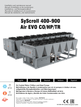
Refrigerant Flow Diagram
COMPONENTS
1 Inverter driven Scroll compressor
2 4-way valve
3 Air cooled condenser
4 Biflow filter drier
5 Sight glass
6 Expansion valve
7 Liquid receiver
8 Plate heat exchanger
9 Inverter driven pump (optional)
10 Drain valve
11 Water buffer tank
12 Water filter (loose)
13 Automatic water charging valve
14 Water outlet
15 Water inlet
16 Water charging line
17 Expansion vessel (lt 5)
18 Suction accumulator
SAFETY/CONTROL DEVICES
A High pressure switch (40,5 bar)
AT High pressure transducer
B Low pressure switch (1,5 bar)
BT Low pressure transducer
C Water differential pressure switch (105 mbar)
D Air temperature sensor
E Outlet water temperature sensor
F Inlet water temperature sensor
FS Flow switch
H Defrost temperature sensor
I Discharge gas temperature thermostat-DGT
L Vent valve
M Discharge temperature sensor
N Water safety valve (3 bar)
S Shrader valve (Service/Charging point)
ST Suction temperature probe
↓ Pipe connection with Shrader valve 1/4” SAE
---- Optional components
° Probes

SYSCROLL 20-30 AIR EVO |11
Operating Limits - SYSCROLL 20 AIR EVO HP
-15
-10
-5
0
5
10
15
20
25
30
35
40
45
50
-10 -8 -6 -4 -2 0 2 4 6 8 10 12 14 16 18 20
OUTDOOR AIR TEMPERATURE OAT [°C]
EVAPORATOR LWT [°C]
Water
Water+Glycol
Cooling operation / Max capacity
-15
-10
-5
0
5
10
15
20
25
30
35
40
45
50
-10 -8 -6 -4 -2 0 2 4 6 8 10 12 14 16 18 20
OUTDOOR AIR TEMPERATURE OAT [°C]
EVAPORATOR LWT [°C]
Water
Water+Glycol
Cooling operation / Nominal capacity
20
25
30
35
40
45
50
55
60
-20 -15 -10 -5 0 5 10 15 20 25
CONDENSER LWT [°C]
OUTDOOR AIR TEMPERATURE OAT [°C]
Heating operation / Max capacity
20
25
30
35
40
45
50
55
60
-20 -15 -10 -5 0 5 10 15 20
25
CONDENSER LWT [°C]
OUTDOOR AIR TEMPERATURE OAT [°C]
Heating operation / Nominal capacity

| SYSCROLL 20-30 AIR EVO
12
Operating Limits - SYSCROLL 30 AIR EVO HP
-15
-10
-5
0
5
10
15
20
25
30
35
40
-10 -8 -6 -4 -2 0 2 4 6 8 10 12 14 16 18 20
OUTDOOR AIR TEMPERATURE OAT [°C]
EVAPORATOR LWT [°C]
Water
Water+Glycol
Cooling operation / Max capacity
-15
-10
-5
0
5
10
15
20
25
30
35
40
45
50
-10 -8 -6 -4 -2 0 2 4 6 8 10 12 14 16 18 20
OUTDOOR AIR TEMPERATURE OAT [°C]
EVAPORATOR LWT [°C]
Water Water+Glycol
Cooling operation / Nominal capacity
20
25
30
35
40
45
50
55
60
-20 -15 -10 -5 0 5 10 15 20
25
CONDENSER LWT [°C]
OUTDOOR AIR TEMPERATURE OAT [°C]
Heating operation / Max capacity
20
25
30
35
40
45
50
55
60
-20 -15 -10 -5 0 5 10 15 20 25
CONDENSER LWT [°C]
OUTDOOR AIR TEMPERATURE OAT [°C]
Heating operation / Nominal capacity

SYSCROLL 20-30 AIR EVO |13
Performances corrective factors (brine)
Unit capacity, absorbed power, brine ow rate, brine pressure drop, have to be corrected according following formula:
CORRECTED UNIT CAPACITY
QCORRECTED/GLYCOL = QNOMINAL x Kc x KcE,P
Where Kc : Capacity corrective factor according to LWT (ΔT = 5 [K]) → refer to Table 1
KcE : Capacity corrective factor according to glycol percentage (ETHYLENE GLYCOL) → refer to Table 2
KcP : Capacity corrective factor according to glycol percentage (PROPYLENE GLYCOL) → refer to Table 4
CORRECTED UNIT ABSORBED POWER
PCORRECTED/GLYCOL = PNOMINAL x Ki x KiE,P
Where Ki : Absorbed power corrective factor according to LWT (ΔT = 5 [K]) → refer to Table 1
KiE : Absorbed power corrective factor according to glycol percentage (ETHYLENE GLYCOL) → refer to Table 2
KiP : Absorbed power corrective factor according to glycol percentage (PROPYLENE GLYCOL) → refer to Table 4
CORRECTED BRINE FLOW RATE
GCORRECTED/GLYCOL = GRE-CALCULATED x KfE,P
Where GRE-CALCULATED : Flow rate according to PCORRECTED/GLYCOL (PCORRECTED/GLYCOL x 860 / ΔT / 3600)
KfE : Flow rate corrective factor according to glycol percentage (ETHYLENE GLYCOL) → refer to Table 2
KfP : Flow rate corrective factor according to glycol percentage (PROPYLENE GLYCOL) → refer to Table 4
CORRECTED BRINE PRESSURE DROP
ΔPCORRECTED/GLYCOL = ΔPRE-CALCULATED x KpE,P
Where ΔPRE-CALCULATED : Pressure drop according to GCORRECTED/GLYCOL (KBPHE x (GCORRECTED/GLYCOL)2)
KpE : Pressure drop corrective factor according to glycol percentage (ETHYLENE GLYCOL) → refer to Table 2
KpP : Pressure drop corrective factor according to glycol percentage (PROPYLENE GLYCOL) → refer to Table 5
Table 1
KcKi
Leaving water
temperature
[LWT] (°C)
(ΔT=5 [K])
7
1,000 1,000
4
0,887 0,940
20,816 0,900
0
0,748 0,865
-2
0,685 0,826
-4 0,624 0,788
-6
0,568 0,753
-8
0,513 0,718
-10 0,461 0,683
Table 2
Ethylene Glycol Percentage
0% 10% 20% 30% 35% 40%
Freezing point (*)
°C
0 -4 -10 -10 -21 -21
Minimum leaving water temperature allowed
°C
6 2 -2 -2 -8 -8
Capacity corrective factor (**)
Kc
E1 0,995 0,985 0,985 0,963 0,963
Absorbed power corrective factor (**)
Ki
E1 0,998 0,995 0,995 0,983 0,983
Flow rate corrective factor
Kf
E1 1,015 1,050 1,050 1,123 1,123
Pressure drop corrective factor (***) K
p
E1 1,070 1,160 1,160 1,283 1,283
(*) ASHRAE Handbook Fundamentals.
(**) Valid for LWT=7 [°C]. If LWT<7 [°C] consider Kc x KcE and Ki x KiE
(***) Valid for LWT > 5 [°C]. If LWT<5°C → refer to Table 3

| SYSCROLL 20-30 AIR EVO
14
Table 3
Ethylene Glycol
Percentage
LWT
[°C]
Corrective factor Kf
ECorrective factor Kp
E
10%
5 1,0154 1,0710
4 1,0154 1,0760
31,0154 1,0810
21,0154 1,0850
20%
1 1,0417 1,1930
0 1,0423 1,2000
-1 1,0428 1,2080
-2 1,0434 1,2150
30%
-3 1,0927 1,2990
-4 1,0936 1,3060
-5 1,0945 1,3200
-6 1,0954 1,3330
Table 4
Propylene Glycol Percentage 0% 10% 20% 30% 40%
Freezing point (*)
°C
0-3 -7 -13 -22
Capacity corrective factor (**)
Kc
P1 0,991 0,977 0,945 0,911
Absorbed power corrective factor (**) K
i
P1 0,994 0,991 0,975 0,966
Flow rate corrective factor
Kf
P1 1,005 1,030 1,067 1,130
(*) ASHRAE Handbook Fundamentals.
(**) Valid for LWT=7 [°C]. If LWT<7 [°C] consider Kc x KcP and Ki x KiP
Table 5
Ethylene Glycol
Percentage
LWT
[°C]
Corrective factor Kp
p
10% 5 1,112
4 1,134
20%
5 1,175
4 1,196
31,206
30%
5 1,290
4 1,300
31,310
01,362
-2 1,393
-4 1,414
40%
5 1,433
4 1,435
31,456
0 1,497
-2 1,549
-4 1,580
-6 1,612
-8 1,653

SYSCROLL 20-30 AIR EVO |15
Model 20 30
NET(1) Data @ Eurovent LCP/A/CHF conditions(2)
Heating capacity - (min / nom / max) kW 9,94 20,4 29,4 11,5 26,1 34,0
Power input kW 2,98 5,02 8,37 3,01 6,45 9,80
COP kW/kW 3,34 4,06 3,51 3,82 4,05 3,47
EUROVENT CLASS A A
Capacity range % 49% -144% 44% -130%
Cooling Capacity - (min / nom / max) kW 9,33 20,0 28,0 13,9 29,0 35,9
Power input kW 2,38 4,15 6,61 3,51 7,24 13,0
EER kW/kW 3,92 4,82 4,24 3,96 4,01 2,76
EUROVENT CLASS A A
Capacity range % 47% -140% 48% -124%
NET(1) Data @ Eurovent LCP/A/AC conditions(3)
Heating capacity - (min / nom / max) kW 8,90 20,4 27,4 10,2 26,1 33,5
Power input kW 3,34 6,44 9,64 3,97 8,42 11,6
COP kW/kW 2,66 3,17 2,84 2,57 3,10 2,89
EUROVENT CLASS B B
Capacity range % 44% -134% 39% -128%
Cooling Capacity - (min / nom / max) kW 6,60 20,0 25,2 9,43 29,0 31,1
Power input kW 2,52 6,65 10,3 3,14 10,7 12,4
EER kW/kW 2,62 3,01 2,45 3,00 2,71 2,51
EUROVENT CLASS B C
Capacity range % 33% -126% 33% -107%
EER 75% kW/kW 3,83 3,65
EER 50% kW/kW 4,53 4,48
EER 25% kW/kW 3,80 4,79
NET(1) ESEER kW/kW 4,08 4,23
SEER (4) 3,75 4,075
hsc (4) 147 160
SCOP (5) 3,43 3,57
hsh (5) 134 140
Number of Refrigerant Circuits 1
Part Load Steps %Stepless
Power Supply V/ph/Hz 400/3+N/50
Startup Type Soft-start (inverter)
Maximum Absorbed Power kW 13,2 15,8
Maximum Current (FLA) A 25,9 30,9
Startup Current (LRA) A 3,9 3,9
Refrigerant
Type R410A
Compressor
Number / Type 1 / Scroll (BLDC Motor)
Crankcase Heater W40
Internal heat exchanger
Number 1
Type Brazed plate
Water ow Rate / Water Pressure Drop l/h / kPa Refer to hydraulic circuit data
Antifreeze Heater W 35
Fans
Number 2 2
Air Flow Rate m³/h 10.848 10.425
Input Power kW 0,54 0,54
Pump
Number 1 1
Input Power kW 0,56 0,63
Water ow Rate / Water Pressure Drop l/h / kPa Refer to hydraulic circuit data
Water Connections
Type Male GAS Threaded
Inlet Diameter / Outlet Diameter inch 1” 1/4
(1) According EN 14511 standard.
(2) Eurovent LCP/A/CHF conditions in heating mode: water heat exchanger EWT/LWT → 30°C/35°C, OAT → 7°C db/6°C WB.
Eurovent LCP/A/CHF conditions in cooling mode: water heat exchanger EWT/LWT → 23°C/18°C, OAT → 35°C.
(3) Eurovent LCP/A/AC conditions in heating mode: water heat exchanger EWT/LWT → 40°C/45°C, OAT → 7°C db/6°C WB.
Eurovent LCP/A/AC conditions in cooling mode: water heat exchanger EWT/LWT → 12°C/7°C, OAT → 35°C.
(4) Following COMMISSION REGULATION (EU) No 2016/2281 for comfort application chillers.
(5) Following COMMISSION REGULATION (EU) No 813/2013 for low-temperature heat pumps.
Technical data

| SYSCROLL 20-30 AIR EVO
16
Electrical Data
Sound Data
Size
Octave Band (Hz) Sound Power
Level dB(A)
Sound Pressure
Level* dB(A)
63 125 250 500 1000 2000 4000 8000
Sound Power Level (dB)
20 84 68 71 70 70 65 59 54 74 42
30
86 69 72 71 70 66 59 56 75 43
* Sound pressure level at 10 m. Values refers to ISO Standard 3744 with parallepiped shape.
SYSCROLL AIR EVO HP 20 30
Power supply V/ph/Hz 400 ± ( 10%)/3+N/50
Maximum power input kW 13,2 15,8
Maximum current input A25,9 30,9
Start-up corrent A3,9 3,9
External fuses A 32 32
Max cable section (*) mm210 10
Heat exchanger resistance
Power supply V/ph/Hz 230 ± ( 10%)/1/50
Maximum power input W35
(*) The dimensioning of the unit’s power cables is the responsibility of the installer, who shall consider: the rating, the maximum working temperature in the room, the type of
insulation and the cable laying, the maximum lenght of the power supply line.
Compressor data
SYSCROLL AIR EVO HP 20 30
Power supply V/ph/Hz 400 ± ( 10%)/3/50
Number 1
Maximum power input kW 11,9 14,4
Nominal current input A15,0 20,0
Maximum current input A22,0 27,0
Crankcase heater (230±(10%)/1/50) W40
Fan data
SYSCROLL AIR EVO HP 20 30
Power supply V/ph/Hz 230 ± ( 10%)/1/50
Number 2
Maximum power input kW 0,3+0,3
Nominal current input A1,3+1,3
Pump data
SYSCROLL AIR EVO HP 20 30
Power supply V/ph/Hz 400 ± ( 10%)/3/50
Number 1
Maximum power input kW 0,72
Nominal current input A1,3
Model 20 30
Weight
Shipping kg 266 281
Operating kg 260 275
Dimensions
Length mm 1.477 1.477
Width mm 539 539
Height mm 1.615 1.615
Acoustic Data
Sound Power Level dB(A) 74 75
Sound Pressure Level(6) dB(A) 43 44
(6) Sound Pressure calculated at 10m. Values refers to ISO Standard 3744 with parallepiped shape.

SYSCROLL 20-30 AIR EVO |17
Nominal performances* (different speeds) - SYSCROLL 20 AIR EVO HP
SYSCROLL 20
AIR EVO HP
OAT (°C)
25 30 35 40 45
PCOOL
(kW)
PABS
(kW)
EER
kW/kW
PCOOL
(kW)
PABS
(kW)
EER
kW/kW
PCOOL
(kW)
PABS
(kW)
EER
kW/kW
PCOOL
(kW)
PABS
(kW)
EER
kW/kW
PCOOL
(kW)
PABS
(kW)
EER
kW/kW
LWT (°C)
5 20,0 5,98 3,34 20,0 7,05 2,84 20,0 7,77 2,57 20,0 9,72 2,06 19,4 11,3 1,71
720,0 5,08 3,94 20,0 5,82 3,44 20,0 6,65 3,01 20,0 8,56 2,34 20,0 10,6 1,89
10 20,0 4,10 4,88 20,0 4,83 4,14 20,0 5,93 3,37 20,0 7,55 2,65 20,0 9,49 2,11
15 20,0 3,60 5,56 20,0 4,08 4,90 20,0 4,72 4,24 20,0 5,96 3,36 20,0 7,49 2,67
18 20,0 3,47 5,76 20,0 3,92 5,10 20,0 4,15 4,82 20,0 5,55 3,60 20,0 7,12 2,81
(*) NET data (according EN 14511 standard).
Cooling operation
SYSCROLL 20
AIR EVO HP
OAT (°C)
-15 -10 -7 -2
PHEAT
(kW)
PABS
(kW)
COP
kW/kW
PHEAT
(kW)
PABS
(kW)
COP
kW/kW
PHEAT
(kW)
PABS
(kW)
COP
kW/kW
PHEAT
(kW)
PABS
(kW)
COP
kW/kW
LWT (°C)
35 12,8 7,67 1,67 16,5 7,82 2,11 19,7 7,95 2,48 20,5 7,59 2,69
40 13,6 8,36 1,62 16,9 8,50 1,99 19,5 8,61 2,26 20,4 8,61 2,37
45 12,3 8,21 1,50 17,3 9,18 1,88 19,3 9,26 2,08 20,4 8,98 2,28
50 9,82 7,42 1,32 14,0 7,97 1,75 16,1 9,44 1,71 20,4 9,87 2,07
55 10,3 7,28 1,42 12,8 8,32 1,54 18,8 9,47 1,98
Heating operation
SYSCROLL 20
AIR EVO HP
OAT (°C)
2 7 12
PHEAT
(kW)
PABS
(kW)
COP
kW/kW
PHEAT
(kW)
PABS
(kW)
COP
kW/kW
PHEAT
(kW)
PABS
(kW)
COP
kW/kW
LWT (°C)
35 20,4 6,68 3,06 20,4 5,02 4,06 20,4 4,40 4,65
40 20,4 7,35 2,78 20,4 6,09 3,36 20,4 4,97 4,11
45 20,4 8,01 2,55 20,4 6,44 3,17 20,4 5,58 3,66
50 20,4 8,46 2,42 20,4 7,14 2,86 20,4 6,23 3,28
55 20,4 8,85 2,31 20,4 8,41 2,43 20,4 6,93 2,95

| SYSCROLL 20-30 AIR EVO
18
Max performances* (different speeds) - SYSCROLL 20 AIR EVO HP
SYSCROLL 20
AIR EVO HP
OAT (°C)
25 30 35 40 45
PCOOL
(kW)
PABS
(kW)
EER
kW/kW
PCOOL
(kW)
PABS
(kW)
EER
kW/kW
PCOOL
(kW)
PABS
(kW)
EER
kW/kW
PCOOL
(kW)
PABS
(kW)
EER
kW/kW
PCOOL
(kW)
PABS
(kW)
EER
kW/kW
LWT (°C)
5 25,6 8,82 2,90 24,4 9,48 2,57 23,4 10,2 2,30 21,3 10,7 1,98 19,4 11,3 1,71
728,6 8,95 3,20 26,8 9,6 2,79 25,2 10,3 2,46 23,0 10,9 2,11 20,9 11,6 1,81
10 33,1 9,13 3,63 30,5 9,8 3,12 27,9 10,4 2,69 25,6 11,2 2,30 23,3 11,9 1,96
15 40,6 9,44 4,30 36,7 10,1 3,64 32,3 10,6 3,04 30,0 11,6 2,60 27,1 12,4 2,19
18 31,5 5,93 5,31 29,4 6,51 4,52 28,0 6,61 4,24 25,6 7,86 3,26 22,9 8,62 2,66
Cooling operation
SYSCROLL 20
AIR EVO HP
OAT (°C)
-15 -10 -7 -2
PHEAT
(kW)
PABS
(kW)
COP
kW/kW
PHEAT
(kW)
PABS
(kW)
COP
kW/kW
PHEAT
(kW)
PABS
(kW)
COP
kW/kW
PHEAT
(kW)
PABS
(kW)
COP
kW/kW
LWT (°C)
35 12,8 7,67 1,67 16,5 7,82 2,11 19,7 7,95 2,48 22,4 8,05 2,79
40 13,6 8,36 1,62 16,9 8,50 1,99 19,5 8,61 2,26 22,3 8,72 2,55
45 12,3 8,21 1,50 17,3 9,18 1,88 19,3 9,26 2,08 22,1 9,39 2,36
50 9,82 7,42 1,32 14,0 7,97 1,75 16,1 9,44 1,71 22,0 10,1 2,18
55 10,3 7,28 1,42 12,8 8,32 1,54 18,8 9,47 1,98
Heating operation
SYSCROLL 20
AIR EVO HP
OAT (°C)
2 7 12
PHEAT
(kW)
PABS
(kW)
COP
kW/kW
PHEAT
(kW)
PABS
(kW)
COP
kW/kW
PHEAT
(kW)
PABS
(kW)
COP
kW/kW
LWT (°C)
35 23,4 8,05 2,90 29,4 8,37 3,52 33,4 8,48 3,94
40 23,8 8,76 2,72 28,5 9,01 3,16 32,1 9,11 3,52
45 24,2 9,47 2,56 27,4 9,64 2,84 30,7 9,74 3,16
50 24,6 10,2 2,42 26,5 10,3 2,58 29,4 10,4 2,84
55 25,1 10,9 2,30 25,5 10,9 2,34 28,1 11,0 2,55

SYSCROLL 20-30 AIR EVO |19
Nominal performances* (different speeds) - SYSCROLL 30 AIR EVO HP
SYSCROLL 30
AIR EVO HP
OAT (°C)
25 30 35 40 45
PCOOL
(kW)
PABS
(kW)
EER
kW/kW
PCOOL
(kW)
PABS
(kW)
EER
kW/kW
PCOOL
(kW)
PABS
(kW)
EER
kW/kW
PCOOL
(kW)
PABS
(kW)
EER
kW/kW
PCOOL
(kW)
PABS
(kW)
EER
kW/kW
LWT (°C)
5 29,0 7,84 3,70 29,0 9,38 3,09 29,0 10,8 2,69 27,1 12,9 2,11 23,0 11,5 2,01
729,0 7,28 3,98 29,0 9,31 3,11 29,0 10,7 2,71 29,0 12,7 2,28 24,0 12,2 1,97
10 29,0 7,13 4,07 29,0 7,69 3,77 29,0 10,1 2,88 28,9 12,1 2,39 24,8 11,2 2,22
15 29,0 5,91 4,91 29,0 6,84 4,24 29,0 7,72 3,76 29,0 10,1 2,88 25,5 9,88 2,58
18 29,0 5,32 5,45 29,0 6,31 4,60 29,0 7,24 4,01 29,0 9,61 3,02 25,9 9,64 2,69
(*) NET data (according EN 14511 standard).
Cooling operation
SYSCROLL 30
AIR EVO HP
OAT (°C)
-15 -10 -7 -2
PHEAT
(kW)
PABS
(kW)
COP
kW/kW
PHEAT
(kW)
PABS
(kW)
COP
kW/kW
PHEAT
(kW)
PABS
(kW)
COP
kW/kW
PHEAT
(kW)
PABS
(kW)
COP
kW/kW
LWT (°C)
35 17,7 8,53 2,07 21,5 8,82 2,43 24,5 9,03 2,71 26,1 8,59 3,04
40 17,8 9,20 1,94 21,5 9,52 2,25 24,0 9,72 2,47 26,1 9,57 2,73
45 18,0 9,87 1,82 21,5 10,2 2,10 23,6 10,4 2,27 26,1 10,6 2,47
50 15,3 10,0 1,53 21,5 10,9 1,96 23,1 11,1 2,08 26,1 10,9 2,40
55 10,5 8,89 1,18 14,4 9,06 1,58 20,1 10,3 1,96 26,1 11,8 2,20
Heating operation
SYSCROLL 30
AIR EVO HP
OAT (°C)
2 7 12
PHEAT
(kW)
PABS
(kW)
COP
kW/kW
PHEAT
(kW)
PABS
(kW)
COP
kW/kW
PHEAT
(kW)
PABS
(kW)
COP
kW/kW
LWT (°C)
35 26,1 7,80 3,35 26,1 6,45 4,05 26,1 5,51 4,74
40 26,1 8,59 3,04 26,1 7,46 3,50 26,1 6,20 4,21
45 26,1 9,32 2,80 26,1 8,42 3,10 26,1 6,94 3,76
50 26,1 10,0 2,61 26,1 9,02 2,89 26,1 7,50 3,48
55 26,1 11,8 2,21 26,1 9,85 2,65 26,1 7,68 3,40

| SYSCROLL 20-30 AIR EVO
20
Max performances* (different speeds) - SYSCROLL 30 AIR EVO HP
SYSCROLL 30
AIR EVO HP
OAT (°C)
25 30 35 40 45
PCOOL
(kW)
PABS
(kW)
EER
kW/kW
PCOOL
(kW)
PABS
(kW)
EER
kW/kW
PCOOL
(kW)
PABS
(kW)
EER
kW/kW
PCOOL
(kW)
PABS
(kW)
EER
kW/kW
PCOOL
(kW)
PABS
(kW)
EER
kW/kW
LWT (°C)
533,6 10,4 3,22 31,9 11,2 2,84 30,3 12,1 2,51 27,1 12,9 2,11 23,0 11,5 2,01
735,2 10,8 3,25 33,6 11,5 2,91 31,1 12,4 2,51 29,0 12,7 2,28 24,0 12,2 1,97
10 36,8 11,0 3,34 35,6 11,9 3,00 33,5 12,8 2,62 28,9 12,1 2,39 24,8 11,2 2,22
15 40,1 11,6 3,45 37,9 12,6 3,01 36,2 13,6 2,67 30,5 11,2 2,72 25,5 9,88 2,58
18 42,5 12,1 3,52 39,8 13,0 3,05 35,9 13,0 2,76 31,1 11,3 2,75 25,9 9,64 2,69
(*) NET data (according EN 14511 standard).
Cooling operation
SYSCROLL 30
AIR EVO HP
OAT (°C)
-15 -10 -7 -2
PHEAT
(kW)
PABS
(kW)
COP
kW/kW
PHEAT
(kW)
PABS
(kW)
COP
kW/kW
PHEAT
(kW)
PABS
(kW)
COP
kW/kW
PHEAT
(kW)
PABS
(kW)
COP
kW/kW
LWT (°C)
35 17,7 8,53 2,07 21,5 8,82 2,43 24,5 9,03 2,71 27,5 9,27 2,97
40 17,8 9,20 1,94 21,5 9,52 2,25 24,0 9,72 2,47 27,3 10,0 2,72
45 18,0 9,87 1,82 21,5 10,2 2,10 23,6 10,4 2,27 27,0 10,8 2,50
50 15,3 10,0 1,53 21,5 10,9 1,96 23,1 11,1 2,08 26,8 11,6 2,31
55 10,5 8,89 1,18 14,4 9,06 1,58 20,1 10,3 1,96 26,5 12,3 2,15
Heating operation
SYSCROLL 30
AIR EVO HP
OAT (°C)
2 7 12
PHEAT
(kW)
PABS
(kW)
COP
kW/kW
PHEAT
(kW)
PABS
(kW)
COP
kW/kW
PHEAT
(kW)
PABS
(kW)
COP
kW/kW
LWT (°C)
35 29,3 9,40 3,12 34,0 9,80 3,47 39,0 10,1 3,86
40 29,5 10,3 2,87 33,8 10,7 3,16 37,8 10,9 3,47
45 29,6 11,1 2,67 33,5 11,6 2,89 36,6 11,7 3,13
50 29,8 12,0 2,49 33,2 12,5 2,66 35,5 12,5 2,84
55 30,0 12,8 2,34 33,0 13,4 2,46 34,3 13,3 2,58
/