M968491 Rev. 1.2
6028.240
DAZZLE
WRENCH
Certified to comply with ANSI A112.18.1
Installation
Instructions
Mini Spread Lavatory Faucet with
Speed Connect Drain*
Adjustable Wrench Screwdriver Channel Locks
Recommended tools
Tubing Cutter
1
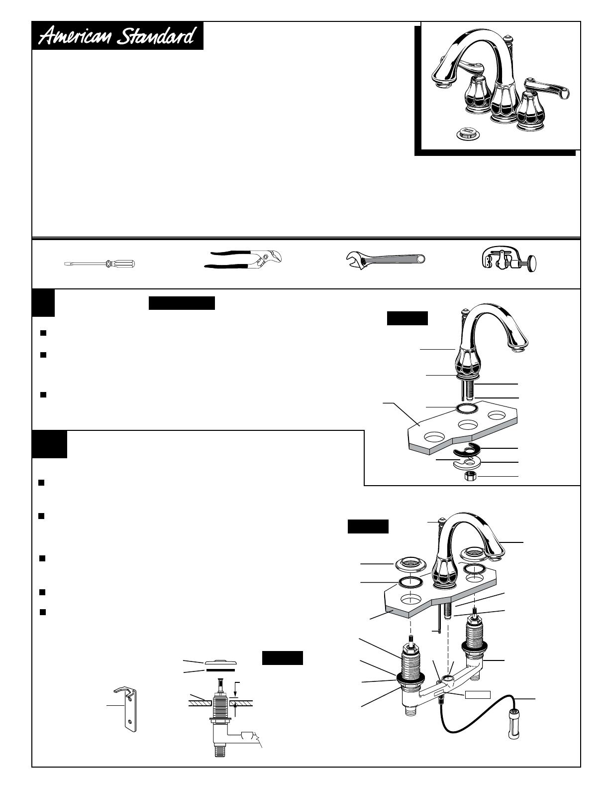
INSTALL FAUCET
SINK OR
MOUNTING
SURFACE
POP-UP
CABLE
Turn off hot and cold water
supplies before beginning.
CAUTION
SINK
5/16'' MIN.
SLOT
Insert SPOUT (1) through center hole of mounting surface, making sure the
SPOUT ESCUTCHEON (2) and SEAL WASHER (3) are properly seated.
Assemble RUBBER WASHER (4), BRASS WASHER (5) and LOCKNUT (6)
onto SPOUT SHANK (7) from under side of sink . Make sure SPOUT (1)
is centered in the sink hole, the slot in the BRASS WASHER (5) is in
back and the O-RING (8) is seated at the end of SHANK (7).
Tighten LOCKNUT (6) on SPOUT (1) firmly. Fig. A.
Drop LIFT ROD (12) through hole in SPOUT (7) and thread ROD
END (13) into the TAB (14) in the VALVE BODY (5). Fig. C.
Install the valve LOCKNUT (1), FRICTION WASHER (2) and RUBBER
WASHER (3) onto the two VALVE SHANKS (4) if not already installed.
The LABEL indicating the front of the fitting faces the front of the sink.
Insert VALVE BODY (5) through holes from under side of SINK. Threads
of both VALVE SHANKS (4) should extent at least 5/16 inch above SINK
top. Fig. B. Be sure SHANK (9) and O-RING (6) of SPOUT (7) is pushed
into TEE (8) section of the VALVE BODY (5). Fig. C.
Install ESCUTCHEONS (10) with RUBBER RINGS (11) and screw
ESCUTCHEONS (10) onto VALVE SHANKS (4) until snug against
internal stop. Adjust LOCKNUTS (1) downward if necessary.
Tighten LOCKNUTS (1) on VALVE SHANKS (4) firmly to secure fitting.
1a
INSTALL VALVE BODY
2
1
3
4
3
6
10
5
11
10
11
2
1
5
6
7
7
8
SINK
FRONT
8
14
13
4
9
12
1
F
RO
N
T
Fig. A.
Fig. B.
Fig. C.
Speed Connect Drain*
• 1/3 of the parts, installs in 1/3 of the time
• No tools needed
• Never needs adjustment
• Guaranteed to seal properly the first time, every time.
To ensure that your installation proceeds smoothly-please read these instructions carefully before you begin.
Congratulations on purchasing your American Standard
faucet with Speed Connect drain, a feature found only on
American Standard faucets.
*Your new American Standard faucet is designed to work only with the Speed Connect drain. Helpful tips for
removing your current drain can be found in the Troubleshooting section of these instructions.


