
Operating Manual
INSYS Modem
INSYS Modem 336 4.1
INSYS Modem 56k 4.1
INSYS Modem 56k UL
File E239995
July 06

Copyright © July 06 INSYS MICROELECTRONICS GmbH
Any duplication of this manual is prohibited. All rights on this documentation
and the devices are with INSYS MICROELECTRONICS GmbH Regensburg.
Restrictions of guarantee
This handbook contains a concise description. The compilation of the text has
been made with the utmost care. Despite all efforts, there may be deviations
compared with the actual functions. No guarantee can therefore be given for
the accuracy of the contents. We can neither take over a legal responsibility nor
any liability for incorrect information and their consequences. Suggestions for
improvements and comments are gladly accepted.
Trademarks
The use of a trademark not shown below is not an indication that it is freely
available for use.
MNP is a registered trademark of Microcom Inc.
IBM PC, AT, XT are registered trademarks of International Business Machine Corporation.
INSYS ® is a registered trademark of INSYS MICROELECTRONICS GmbH.
Windows™ is a registered trademark of Microsoft Corporation.
Publisher:
INSYS MICROELECTRONICS GmbH
Waffnergasse 8
93047 Regensburg, Germany
Phone: 0941/58692-0
Fax: 0941/563471
E-mail: [email protected]
Internet: http://www.insys-tec.de
Subject to technical changes as well as correction.
Date:
July 06
Item number: 31-22-03.034 english

INSYS Modem 336/56k 4.1 (UL) Contents
1 SCOPE OF DELIVERY....................................................7
2 GENERAL.....................................................................7
3 NOTES REGARDING THE USE OF THE MANUAL..........8
4 DESCRIPTION..............................................................9
4.1 FRONT PANEL ............................................................................9
4.2 TOP.........................................................................................9
4.3 BOTTOM ................................................................................10
4.4 USER PROFILE..........................................................................10
4.5 CONFIGURATION SOFTWARE HSCOMM .......................................11
4.6 INSTALLATION INSTRUCTIONS.....................................................14
5 FUNCTIONS...............................................................17
5.1 CONFIGURATION .....................................................................17
5.2 SERIAL DATA TRANSMISSION .....................................................19
5.3 ERROR CORRECTION .................................................................23
5.4 DATA COMPRESSION ................................................................24
5.5 SELECTIVE CALL ANSWER...........................................................26
5.6 SWITCH OUTPUT .....................................................................27
5.7 ALARM INPUT .........................................................................28
5.8 SEND MESSAGES .....................................................................30
5.9 REMOTE CONFIGURATION (REMOTE CONTROL).............................32
July 06 3

Contents INSYS Modem 336/56k 4.1 (UL)
5.10 REMOTE SWITCHING AND REMOTE QUERY VIA DTMF....................34
5.11 ACCESS CONTROL ....................................................................36
5.12 DATA TRANSMIT CONTROLLER (IDLE CONNECTION CONTROL)..........38
5.13 PRIORITY CIRCUIT FOR MODEMS WITH PHONES CONNECTED IN SERIES
39
6 OPERATION WITH A PLC...........................................42
7 FIRMWARE UPDATE .................................................43
7.1 FLASHCOM.EXE .......................................................................43
7.2 TERMINAL PROGRAM................................................................44
8 AT COMMAND SET ...................................................46
8.1 OVERVIEW AT COMMANDS.......................................................47
8.2 OVERVIEW FAX AND VOICE COMMANDS .....................................73
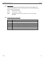
8.3 AT MESSAGES.........................................................................73
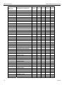
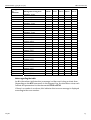
9 S REGISTRY ...............................................................76
9.1 OVERVIEW S REGISTRY .............................................................76
9.2 DESCRIPTION S REGISTRY ..........................................................77
10 SENDING OF SMS AS FAX OR E-MAIL .......................86
10.1 SMS AS FAX ...........................................................................86
10.2 SMS AS E-MAIL ......................................................................87
11 FAQ...........................................................................88
4 Juli 06

INSYS Modem 336/56k 4.1 (UL) Contents
12 SAFETY INSTRUCTIONS.............................................90
12.1 GENERAL................................................................................90
12.2 SMS .....................................................................................90
12.3 CLEANING...............................................................................90
13 TECHNICAL DATA......................................................91
13.1 MECHANICAL FEATURES............................................................91
13.2 POWER SUPPLY .......................................................................91
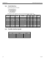
13.3 SERIAL INTERFACE ....................................................................92
13.4 POSSIBLE INTERFACE SPEEDS ......................................................92
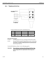
13.5 TELEPHONE INTERFACE..............................................................93
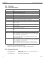
13.6 STANDARDS............................................................................94
13.7 RESET ....................................................................................95
13.8 DIGITAL INPUTS AND OUTPUTS ..................................................95
13.9 CERTIFICATIONS.......................................................................95
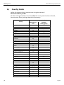
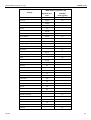
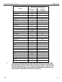
14 COUNTRY CODES......................................................96
July 06 5


INSYS Modem 336/56k 4.1 (UL) Scope of Delivery
1 Scope of Delivery
Before you begin with the initial operation, please check if all accessories are in-
cluded in the box.
¾ INSYS Modem 336 4.1, INSYS Modem 56k 4.1, or INSYS Modem 56k 4.1 UL
¾ 2 phone cords (TAE-N at RJ12 and RJ12 at RJ12), not for version UL.
¾ PC connection cable 9/9-pin (RS232 cable)
¾ User Guide
In case the content is not complete please contact your supplier. Please also check
the modem for shipping damage. Please also refer to your supplier if damage ex-
ists.
Please keep the packaging material for possible future dispatch or storage.
2 General
The INSYS Modem 336/56k 4.1 (UL) is suitable for the analogue phone network. It
has a very compact design and very robust plastic housing. The modem supports
the following functions, which are described in detail in the following:
¾ Establishing a data connection
¾ Automatic call
¾ Alarm inputs and outputs for SMS dispatch and to establish an alarm data
connection
¾ Pulse input to send up to 10 SMS messages
¾ Fax dispatch at alarm release
¾ Local or remote configuration
¾ Usage in 87 countries
¾ Auto answer
¾ Data flow control
¾ Data compression
¾ Error correction
¾ Idle connection control
¾ Flash update
¾ Security callback
July 06 7

Notes Regarding the Use of the Manual INSYS Modem 336/56k 4.1 (UL)
3 Notes Regarding the Use of the Manual
¾ This manual uses the symbol for especially important notes. Further notes
will be marked accordingly.
¾ All factory settings are marked “default”.
Example (Chap. 5.7.3): Enter old password (default: QWERTY)
¾ In Chapters 4 to 6 the description consists of two columns. Individual func-
tions are described on the left side. The according AT commands and the mo-
dem responses can be found in the right column.
Function description AT command
Example (Chap. 5.2.7):
After the hardware reset, load the user profile 1 ATZ1
¾ All AT commands start with the letters AT and end with a “Return” (Carriage
Return - CR). AT commands can be entered in capital or small letters. The
command is evaluated as soon as the modem received a return.
¾ In the following, the used syntax is explained:
c ATDT AT command (font: Courier, bold)
d <Term> Input of a parameter (font: Courier, bold)
e [Term] Input of an optional parameter (font: Courier, bold)
f Term Response from the modem (font: italic)
Examples:
cATDT<n> Dialing the phone number <n>
ATDT1234 Dialing the phone number 1234
d+e AT+MS=<Modulation>, [Automode] Select modulation type
AT+MS=V92 Select modulation type
V.92
AT+MS=V92,1 Select modulation type
V.92 with automatic
adjustment
f Connect Connection to the remote terminal has been
established.
> Input prompt during the remote configuration.
8 July 06

INSYS Modem 336/56k 4.1 (UL) Description
4 Description
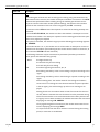
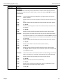
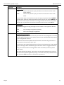
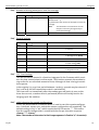
4.1 Front panel
The INSYS Modem 336/56k 4.1 (UL) has four LED’s to indicate the operating state.
Name Color LED off LED on
Power Green No supply voltage Supply voltage available
OH
(Off Hook)
Yellow Modem is offline Modem is hooked to the phone line
(online)
DCD
(Data Carrier Detect)
Yellow No connection is estab-
lished
The connection to the remote terminal
is established (Carrier detected)
RX/TX
(Receive / Transmit)
Green No data exchange Date is exchanged via the modem
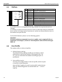
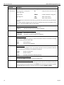
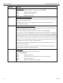
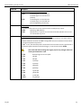
4.2 Top
Terminal Meaning
1 GND Ground
2 X1 Reserved
3 10 ... 60VDC Power supply 10V - 60V DC
4 GND Ground
5 GND Ground
6 Reset Reset input
7 GND Ground
8 Input 1 Alarm input 1
9 Input 2 Alarm input 2
1
2
4
5
6
7
8
9
10
3
GND
GND
X1
GND
Reset
GND
Input 1
Input 2
GND
10...60 VDC
1
2
4
5
6
7
8
9
10
3
Power
supply
IN 1
IN
Ext.
Reset
2
10 GND Ground
July 06 9

Description INSYS Modem 336/56k 4.1 (UL)
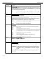
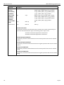
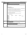
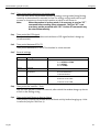
4.3 Bottom
Terminal Meaning
11 OUT1NC Output 1 normally closed
12 OUT1 Output 1
13 OUT1NO Output 1 normally open
14 OUT2NC Output 2 normally closed
15 OUT2 Output 2
16 OUT2NO Output 2 normally open
17 b2 Looped-through telephone connection
18 b1 Phone line to network provider
19 a1 Phone line to network provider
OUT 1-NC
OUT 1
OUT 2-NC
OUT 2
OUT 2-NO
OUT 1-NO
b2
b1
a1
a2
Line
20
19
11
12
13
14
15
16
17
18
11
12
13
14
15
16
17
18
19
20
20 a2 Looped-through telephone connection
a1 and b1 are the incoming phone lines (e.g. outside line or private branch ex-
change).
a2 and b2 are used to connect a phone in series. In idle state, they are connected
to a1 and b1 via a loop current connector. a2 and b2 are disconnected as soon as
the modem occupies the line.
For the INSYS Modem 56k 4.1 UL, the following applies:
Attention!
All devices which are connected to a1, b1, a2 and b2, must comply with the re-
quirements of UL 60950-1, Section 6. The used phone cords must have the type
AWG 26.
4.4 User Profile
The modem offers a choice of profiles:
¾ Default factory setting:
The default factory settings enable you to achieve a fixed
defined basic state of the modem. Starting with this “ba-
sis”, you can customize the modem according to your re-
quirements.
¾ User profiles 0 and 1:
You can save configurations in the user profile, which may be
re-used for certain purposes.
A part of the S registry is saved in each profile. In the descrip-
tion, the affected registries are marked with an “*” in the S
registry.
10 July 06

INSYS Modem 336/56k 4.1 (UL) Description
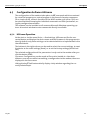
4.5 Configuration Software HSComm
The configuration of the modem takes place via AT commands which are entered
by a terminal program or a control program in the form of character sequences.
For a simple set-up, all basic functions of the INSYS modem 336/56k 4.1 (UL) can
be entered without knowing the individual commands and their parameters, us-
ing the configuration software.
The software can be installed on all common Microsoft Windows operating sys-
tems. A terminal window to enter commands directly is available.
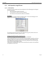
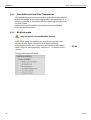
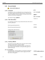
4.5.1 HSComm Operation
At the start or via the menu Device -> Read settings, HSComm verifies the con-
nected device and displays the device name and the firmware in the program win-
dow. By default, only those settings can be selected which are implemented in the
identified device.
The buttons in the right column can be used to select the current settings, to reset
the device to the saved settings (Reset), or to set the factory settings (default val-
ues).
The selected configuration of the parameters is only sent to the modem after you
click the button SEND.
File menu: Configurations can be saved as files and re-loaded at a later date.
When an error occurs while transmitting a configuration to the modem, these are
displayed in the Error menu.
Hitting the key F1 will automatically display a help window regarding the cur-
rently selected topic.
July 06 11

Description INSYS Modem 336/56k 4.1 (UL)
4.5.2 Initial operation using HSComm
4.5.2.1 Serial interface
Control/PC and the modem must be modulated via the following joint settings of
the serial interface:
¾ Baud rate (Data transmission speed)
¾ Format (Start bit, data bits, parity, stop bits)
¾ Data flow control (Hardware/software handshake)
PC Settings
Serial interface settings of the PC (Interface menu) – the current settings are dis-
played in the message bar of the main window.
This setting must also be entered at the application (e.g. SPS), which is later con-
nected to the INSYS modem 336/56k 4.1 (UL).
Settings at the INSYS modem 336/56k 4.1 (UL)
Handshake setting at the modem (Configure menu
Æ
Modem):
Auto bauding: With the first AT command, the INSYS Modem 336/56k 4.1 (UL) rec-
ognizes the baud rate and the format of the incoming data and configures itself
accordingly. When the modem doesn’t receive AT commands but user data right
away, the last saved settings are kept.
If more data is available than what can be received by the modem, the handshake
will regulate the data flow.
12 July 06

INSYS Modem 336/56k 4.1 (UL) Description
DTR Behavior
The signal Data Terminal Ready (DTR) on the serial interfaces indicates that the
connected device (control, PC) is switched on, connected and ready for operation.
The INSYS Modem 336/56k 4.1 (UL) may react to the device being switched off or
the cable being removed.
Echo
With the setting Echo the modem sends each command back via the serial inter-
face. During terminal operation, this makes it obvious which commands are en-
tered.
July 06 13

Description INSYS Modem 336/56k 4.1 (UL)
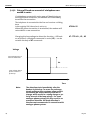
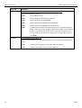
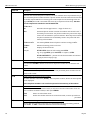
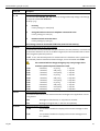
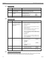
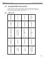
4.6 Installation Instructions
Note: For the installation of the INSYS modem with the configuration soft-
ware HSComm, please also read Chapter 4.5.
Important Safety Instructions
When using the communication device and its accessories, the following safety
instructions must be observed at all times to prevent fire, electric shock or per-
sonal injury.
1. The device may not be used in wet environments, damp rooms or close to
water, e.g. close to bath tubs, wash basins, sinks, wet floors or swimming
pools.
2. The device should not be used during a thunderstorm, as this could result
in electrical shock.
3. The device may not be used when smell of gas or gas leakage is apparent,
to prevent fire hazards or an explosion.
Please comply with these instructions!
TAE-Buchse
RS232
Spannungsversorgung
PC / Maschine
14 July 06

INSYS Modem 336/56k 4.1 (UL) Description
Please observe our safety instructions.
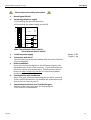
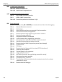
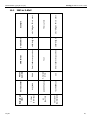
1. Mounting on DIN rail
2. Connecting the power supply
a) Connecting the ground connection
b) Connecting the power supply 10..60V DC
1
2
4
5
6
7
8
9
10
3
GND
GND
X1
GND
Reset
GND
Input 1
Input 2
GND
10...60 VDC
1
2
4
5
6
7
8
9
10
3
Power
supply
IN 1
IN 2
Ext.
Reset
Note: The minimum value is 10V DC.
The maximum value is 60V DC.
Power-LED
lights up
3. Switch on power supply
4. Connection with the PC
Connect the 9-pin jack at the modem with the serial interface
of your computer.
5. Driver Installation
If you use a terminal program or the HSComm program, the
installation of a driver is not necessary. If you use another ap-
plication, a driver may be necessary. Please find our current
drivers at
http://www.insys-tec.de/ or install the standard
modem 336 under Windows.
6. Communication with the Modem
Now, start your communication program on the PC and set it
to the used COM interface. The modem will automatically ad-
just to the baud rate of your PC.
7. Communication Control via a Terminal Program
Perform a short test using your terminal program.
(TeraTermPro, ProcommPlus).
July 06 15

Description INSYS Modem 336/56k 4.1 (UL)
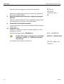
Open the terminal program and enter the command.
When the message appears on your monitor, the device has
been successfully installed.
AT Enter
LED RXTX
leuchtet kurz
OK
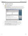
8. Check the communication using the configuration program
HSComm
Open the installed HSComm. The configuration program will
automatically search for the connected modem.
9. Connection to the telephone network
Connect the phone outlet and the modem with the supplied
phone cord.
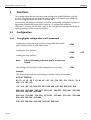
10. Connection Test
Establish a connection, either to another modem or, in this
example, to Freenet.
Dial the following number: 0101901929
For PBXs that require a code number to establish a
connection - usually “0”- a different command
must be used.
The modem will establish a connection.
ATDT 0101901929
ATX3DT 0,0101901929
LED OH lights up
Connect…
16 July 06

INSYS Modem 336/56k 4.1 (UL) Functions
5 Functions
This chapter describes the functions and settings of the INSYS Modem 336/56k
4.1 (UL). The settings can be selected and changed via AT commands, using any
terminal program (Hyperterminal, TeraTerm, etc.)
Alternatively, all common settings can also be comfortably performed via the con-
figuration software HSComm (see Chapter 4.5 "Configuration software
HSComm”). Usually, you will find a part of the configuration software with the ac-
cording settings in the respective chapter.
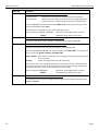
5.1 Configuration
5.1.1 Changing the configuration via AT commands
Loading the factory settings into the active profile will enable
you to easily recover an executable state.
Loading the user profile 0
Loading the user profile 1
Note: Prior to the loading of the user profile, a reset is per-
formed.
The settings of all profiles can be displayed in an overview.
Example:
The active profile will show all settings currently used by the modem.
ACTIVE PROFILE:
B3 E1 L1 M1 Q0 T V1 W0 X4 *A1 *L0 *M0 *P0 *R1 *Y0,0 *Y1,0
%B0 %C3 %E2 %S0
\A1 \D0 \N3 \V0 &A0 &C1 &D2 &G0 &K3 &Q5 &R1 &S0 &X0 &Y0
S00:005 S01:000 S02:043 S03:013 S04:010 S05:008 S06:003
S07:050 S08:002 S09:006
S10:014 S11:085 S12:050 S13:003 S15:000 S17:042 S18:000
S24:000 S25:005 S26:001
S36:135 S38:020 S46:138 S48:007 S95:000
AT&F
ATZ0 ATZ
ATZ1
AT&
V
July 06 17

Functions INSYS Modem 336/56k 4.1 (UL)
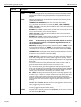
Our example currently shows the settings from user profile 0.
User profile 0:
STORED PROFILE 0:
B3 E1 L1 M1 Q0 T V1 W0 X3 *A1 *L0 *M0 *P0 *R1 *Y0,0 *Y1,0
%B0 %C3 %E2 %S0
\A1 \D0 \N3 \V1 &A0 &C1 &D2 &G0 &K3 &Q5 &R1 &S0 &X0
S00:005 S02:043 S06:003 S07:050 S08:002 S09:006 S10:014
S11:085 S12:050 S13:003
S15:000 S17:042 S18:000 S24:000 S36:135 S40:104 S41:195
S46:138 S95:000
User profile 1:
STORED PROFILE 1:
B3 E1 L1 M1 Q0 T V1 W0 X4 *A1 *L0 *M0 *P0 *R1 *Y0,0 *Y1,0
%B0 %C3 %E2 %S0
\A1 \D0 \N3 \V0 &A0 &C1 &D2 &G0 &K3 &Q5 &R1 &S0 &X0
S00:005 S02:043 S06:003 S07:050 S08:002 S09:006 S10:014
S11:085 S12:050 S13:003
S15:000 S17:042 S18:000 S24:000 S36:135 S40:104 S41:195
S46:138 S95:000
Note: The user profiles 0 and 1 can be modified without affecting the active pro-
file.
Storage location for the phone numbers:
TELEFONNUMMERN:
0= <Z0> 1= <Z1>
2= <Z2> 3= <Z3>
18 July 06

Functions INSYS Modem 336/56k 4.1 (UL)
19 Juli 06
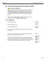
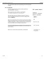
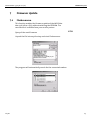
5.1.2 Save Configuration
If the modem configuration was adjusted to certain user
requirements, these settings can be saved in the user pro-
files 0
or 1.
Configuration changes will be lost after a RESET or restart
if they were not saved before.
AT&W0 AT&W
AT&W1
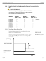
5.2 Serial Data Transmission
5.2.1 Automatic Baud Rate Detection
For each received AT command, the modem automati-
cally performs an adjustment to the set baud rate, the
number of data and stop bits, and the parity.
The adjustment to the transmission speed on the phone
line is performed automatically, unless the settings say
otherwise. During the establishing of a connection both
modems attempt to achieve the joint fastest speed on
the phone line.
For an existing connection, the modem must first switch
to command mode.
You will receive the transmission settings …
E.g.: +MS: V92,1,300,48000,300,56000
This means that a connection between 300 and 56000
bps was established, preferably according to V.92, de-
pending on the line quality and the abilities of the re-
mote terminal.
Query the quality of an existing connection
Query the level of an existing connection
Display the connection statistics after the connection is
terminated
+++
AT+MS?
AT%Q
AT%L
AT&V1

Functions INSYS Modem 336/56k 4.1 (UL)
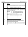
5.2.2 Data Buffer for Serial Data Transmission
The modem has a fast send and receive cache (so-called buffer) to
adjust the modem to the operating speed of the application. It is,
however, possible to deactivate this data buffering and switch to
bit direct mode.
When working with buffers, handshake is recommended to
avoid transmission errors.
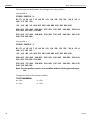
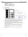
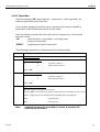
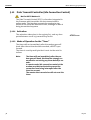
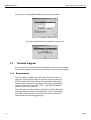
5.2.3 Bit direct mode
Only for special, non-standard data formats
In bit direct mode, the modem has no influence on the trans-
mission format. Data is transmitted without buffering.
Data compression or error correction will not work in bit direct
mode. Only the abort sequence - default +++ - is utilized by the
modem.
AT\N1
Configuration with HSComm:
20 July 06
Page is loading ...
Page is loading ...
Page is loading ...
Page is loading ...
Page is loading ...
Page is loading ...
Page is loading ...
Page is loading ...
Page is loading ...
Page is loading ...
Page is loading ...
Page is loading ...
Page is loading ...
Page is loading ...
Page is loading ...
Page is loading ...
Page is loading ...
Page is loading ...
Page is loading ...
Page is loading ...
Page is loading ...
Page is loading ...
Page is loading ...
Page is loading ...
Page is loading ...
Page is loading ...
Page is loading ...
Page is loading ...
Page is loading ...
Page is loading ...
Page is loading ...
Page is loading ...
Page is loading ...
Page is loading ...
Page is loading ...
Page is loading ...
Page is loading ...
Page is loading ...
Page is loading ...
Page is loading ...
Page is loading ...
Page is loading ...
Page is loading ...
Page is loading ...
Page is loading ...
Page is loading ...
Page is loading ...
Page is loading ...
Page is loading ...
Page is loading ...
Page is loading ...
Page is loading ...
Page is loading ...
Page is loading ...
Page is loading ...
Page is loading ...
Page is loading ...
Page is loading ...
Page is loading ...
Page is loading ...
Page is loading ...
Page is loading ...
Page is loading ...
Page is loading ...
Page is loading ...
Page is loading ...
Page is loading ...
Page is loading ...
Page is loading ...
Page is loading ...
Page is loading ...
Page is loading ...
Page is loading ...
Page is loading ...
Page is loading ...
Page is loading ...
Page is loading ...
Page is loading ...
Page is loading ...
Page is loading ...
-
 1
1
-
 2
2
-
 3
3
-
 4
4
-
 5
5
-
 6
6
-
 7
7
-
 8
8
-
 9
9
-
 10
10
-
 11
11
-
 12
12
-
 13
13
-
 14
14
-
 15
15
-
 16
16
-
 17
17
-
 18
18
-
 19
19
-
 20
20
-
 21
21
-
 22
22
-
 23
23
-
 24
24
-
 25
25
-
 26
26
-
 27
27
-
 28
28
-
 29
29
-
 30
30
-
 31
31
-
 32
32
-
 33
33
-
 34
34
-
 35
35
-
 36
36
-
 37
37
-
 38
38
-
 39
39
-
 40
40
-
 41
41
-
 42
42
-
 43
43
-
 44
44
-
 45
45
-
 46
46
-
 47
47
-
 48
48
-
 49
49
-
 50
50
-
 51
51
-
 52
52
-
 53
53
-
 54
54
-
 55
55
-
 56
56
-
 57
57
-
 58
58
-
 59
59
-
 60
60
-
 61
61
-
 62
62
-
 63
63
-
 64
64
-
 65
65
-
 66
66
-
 67
67
-
 68
68
-
 69
69
-
 70
70
-
 71
71
-
 72
72
-
 73
73
-
 74
74
-
 75
75
-
 76
76
-
 77
77
-
 78
78
-
 79
79
-
 80
80
-
 81
81
-
 82
82
-
 83
83
-
 84
84
-
 85
85
-
 86
86
-
 87
87
-
 88
88
-
 89
89
-
 90
90
-
 91
91
-
 92
92
-
 93
93
-
 94
94
-
 95
95
-
 96
96
-
 97
97
-
 98
98
-
 99
99
-
 100
100


Ask a question and I''ll find the answer in the document
Finding information in a document is now easier with AI
Related papers
-
Insys Modem 56k 4.2 Owner's manual
-
-
-
-
-
-
-
-
-
Other documents
-
Multi-Tech Systems Network Card MT2834ZDX User manual
-
Multitech MT2834ZDX User manual
-
Black Box MD1640A User manual
-
Sitecom DC-009 Datasheet
-
Abocom UCM560 User manual
-
WTI MT5634/MT9234 Internal Modem User manual
-
 Western Telematic MT5634 User manual
-
Maestro Executive 144FM Technical Reference Manual
-
Planet UM-560 User manual
-
Westermo TD-33 DC User guide
