Page is loading ...

Make sure you park the vehicle on a level concrete or asphalt surface. Many times a vehicle is un
level (side-to-side) from the factory, but usually not noticed until a lift kit has been installed which
makes the difference more visible. Using a measuring tape, measure the front and rear (both sides)
from the ground up to the center of the fender opening above the axle. Record below for future ref-
erence.
Driver Side Front: Passenger Side Front:
Driver Side Rear: Passenger Side Rear:
IMPORTANT NOTES:
• Draglink must be adjusted to center steering wheel before vehicle is driven. Failure to do so
will cause computer errors, odd handling characteristics and poor performance.
• Vehicles with 5" or more in lift, it is recommended to order rear Cam-Bolt kit for proper rear
Pinion Angle, Skyjacker Part# CAM700. In some applications a replacement rear driveshaft
may be required, Please contact Skyjacker for more information.
• Please refer to Parts List to insure that all parts and hardware are received prior to disassembly of
vehicle. If any parts are found to be missing, contact your dealer as soon as possible.
• After installation of Suspension Lift, A qualified alignment facility is required to re-align the vehicle
to factory settings.
Jeep Wrangler JK 2/4 Door
2.5"-5” Suspension Lift
Installation Instructions
www.skyjacker.com
I-JK401 5-8 Pg 1
Before beginning the installation, read these instructions and the enclosed driver’s WARNING
NOTICE thoroughly and completely. Also affix the WARNING decal in passenger compartment in
clear view of all occupants. If any of these items are missing from this instruction packet, do not pro-
ceed with installation, but call SKYJACKER®to obtain needed items. If you have any questions or
reservations about installing this lift kit, call SKYJACKER®at 318-388-0816 for Technical Assistance
or Customer Service departments.
Required Tools List:
• Standard / Metric Wrenches and Sockets
• Floor Jack
• Jack Stands
• Assorted Drill Bits

Kit Box Breakdown:
JK401/JK2501:
ITEM# DESCRIPTION QTY
JKLL24F-L JK LOWER FRONT LINK 2-4" 2
JKLL24R-L JK LOWER REAR LINK 2-4" 2
HB-JKLL175 HDWAR BAG: JK FRONT LOWER LINK 1
HB-LL175 HRDWR BAG: JK REAR LOWER LINK 1
JK40RBS-S JK 4" REAR BUMP STOP BRACKET 2
ABSS3040 BUMP STOP SPACER,4" TALL (4” only) 2
JKFTB-B JK 4" FRONT TRACK BAR BRACKET (4” only) 1
JK24RTB-B JK 2-4" REAR TRACK BAR BRACKET 1
SBE126 DOUBLE DISCONNECT LINKS 4" JEEP JK 1
SBE504 SWAY BAR END LINKS JK 4" REAR 1
HB-JK40 HRDWR BAG: JK 4" KIT 1
HB-JK4BL HDWR BAG:JK 4" BRAKE LINE BRACKETS 1
JKBRC15 JK Rear Track Bar Brace Dana 44 1
Hardware Bag Breakdown:
HB-JK40
ITEM# DESCRIPTION QTY
14X80MMB 14MM X 80 METRIC BOLT/ 10.9 1
14MMN 14MM NYLON INSERT LOCK NUT 1
12X114FTB 1/2 X 1 1/4 FINE THD BOLT 1
12SAEW 1/2 SAE WASHER 1
12FTN 1/2-20 FINE N/I LOCK NUT 1
38X4BHB 3/8 X 4 BUTTON HEAD BOLT 2
38SAEW 3/8 SAE WASHER 2
38CTN 3/8-16 COARSE N/I LOCK NUT 2
516X1FTB 5/16 X 1 FINE THRD BOLT 4
516SAEW 5/16 SAE WASHER 8
516FTN 5/16" FINE THRD N/I LOCKNUT 4
716X1FTB 7/16 X 1 BOLT,FINE THD GRD8 1
716X212FTB 7/16 X 2 1/2 FINE THRD BOLT 2
716SAEW 7/16 SAE WASHER 5
716FTN 7/16-20 FINE N/I LOCK NUT 3
916X3FTB 9/16 X 3 FINE THREAD BOLT 1
916SAEW 9/16 SAE WASHERS 5
916FTN 9/16-18 NYLON INSERT LOCKNU 2
CS1625 CRUSH SLEEVE JK24RTB 1
916X312FTB 9/16 X 3 1/2 FINE THRD BOLT 1
Pg 2I-JK401

Hardware Bag Breakdown:
HB-JK4BL
ITEM# DESCRIPTION QTY
DVL10 BRAKE LINE BRKT, JK PASS REAR 1
JKBE4D BRAKE LINE BRKT, JK DRVR REAR 1
516X1FTB 5/16 X 1 FINE THRD BOLT 2
516SAEW 5/16 SAE WASHER 4
516FTN 5/16" FINE THRD N/I LOCKNUT 2
Hardware Bag Breakdown:
Pg 3
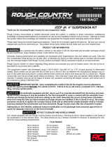
Photo #2
Photo #3
Photo #1
Front Installation:
1. Park the vehicle on flat, level ground and set emergency brake.
2. Raise the front of the vehicle and support frame rails using jack
stands.
3. Disconnect the front sway bar end links using a 18mm socket.
Disconnect front track bar using a 21mm socket. (See Photo
#1)
4. If installing Skyjacker Steering Stabilizer Part# 7003, Remove
factory steering stabilizer using 18mm socket. (See Photo #2)
5. Disconnect front shocks using a 18mm socket. Remove front
tires/wheels and remove front coils. (See Photo #3) Remove
front Shocks.Mark driveshaft & yoke then remove.

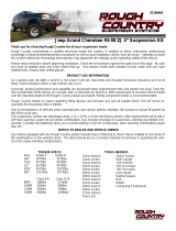
6. Locate new Skyjacker front bump stop. Place bump stop on the center of
the bump stop pad located on the front axle. Mark and drill using a 25/64"
drill bit. (See Photo #4).
7. Place bump stop in coil spring, and install coil spring. Attach bump stop to
axle using the 3/8 X 4" button head bolts with one washer under the nut.
(See Photo #5) (4” only)
8. Locate the factory front track bar mount. Place the new Skyjacker reloca-
tion bracket inside the factory mount. Drill out the outer factory holes all
the way through the rearward plate using a 7/16" drill bit. (See Photo #6)
NOTE: It is recommended at this time to put a re-enforced weld on the fac-
tory bracket. Attach the bracket at the outer two locations using the 7/16 x
2 1/2" fine thread bolts, washers and nuts. Attach bracket at the factory
location using the factory bolt. Let the weight of the frame down on to the
new coils. Attach track bar to new bracket using the 14x80mm bolt, wash-
ers and nut. (4” only)
9. Re-Attach front drive shaft. Assemble new Sway bar end links using the
5/8" Hourglass bushings and steel sleeves. Attach eyes using the 1/4"
snap pins. Attach end link to the axle using the factory hardware. (See
Photo #7) Attach the lower portion of the sway bar using the 1/2 x 2 1/2"
button head bolt. Use one large USS washer under the nut. Re-Attach front
Drive Shaft.
If installing Skyjacker Steering Stabilizer Part # 7003, install at this time.
(See Photo Below).
10. Install new Front Skyjacker shocks using hardware supplied. (See Photo
#8). Locate new Skyjacker Lower front control arms. Install bushings and
sleeves. Install 3/16" Tap in grease fittings into each end of the control arm.
Note: The rear of the control arms have 2 locations for grease fittings.
Therefore there is not a left or right control arm. When installed, one
grease fitting will be accessible from the bottom. Install arms so that off set
bend is toward the inside of the vehicle. Install using factory hardware.
(See Photo #9)
Photo #4
Photo #5
Photo #6
Photo #7 Photo #8
I-JK401 Pg 4
Photo #9

Install tires and wheels. Lower vehicle to the ground.
Note: Most models come equipped with a front transmission
cross member. This cross member has 3 attachment points. One
at each frame rail and one at the rear cross member. It will be
necessary to lower this cross member using the supplied 1" spac-
ers for driveline clearance. Install spacers using the 12 x 65 mm
bolts supplied.
Rear Installation:
11. Raise rear end and properly support frame rails using jack stands.
Remove rear shocks using 16mm socket. (See Photo #10)
12. Disconnect rear track bar bracket from the axle using 21mm sock-
et. (See Photo #11). Disconnect rear sway bar end links using
18mm socket.
13. Disconnect ABS line from frame and disconnect brake line from
frame. (See Photo #12) Lower axle down and remove factory rear
coils.
14. Place Skyjacker rear Track Bar relocation bracket over factory
bracket on the axle. With bracket seated flush, mark and drill the
new center mounting holes using a 15/32" drill bit. (See Photo 13)
15. Install the supplied 7/16 x 1" fine thread bolt and fine thread nyloc
nut. Use one 7/16" washer under the nut. (See Photo #14).
Tighten nut at this time.
16. It will be necessary to drill through the driver side bottom of the
OEM bracket and through the Skyjacker bracket. Drill using a
17/32" drill bit. Once drilled, install the supplied 1/2" x 1 1/4" fine
thread bolt and nyloc nut. Use one washer under the bolt. Install
the 9/16 x 3 1/2" bolt, washers and nut at the bottom location
being sure to use the supplied crush sleeve. (See Arrow in Photo
#15) Tighten all track bar bracket hardware at this time.
17. Install new Skyjacker Softride® rear coils. Be sure to re-use the
upper OE Rubber isolator pad.
Photo #10
Photo #11
I-JK401 Pg 5
Photo #12
Photo #13
Photo #14 Photo #15 Photo #16

18. Attach new rear bump stops to the factory location on the axle
using the 5/16 x 1" fine thread bolts, washers and nuts supplied.
(See Photo #17) Be sure to install the bump stop so that the
angled end is towards the rear.
19. Let weight on coil springs. Install new sway bar end links using
the supplied 5/8" hourglass bushings and steel sleeves. Attach
using the 1/2 x 2 1/2 button head bolts and nuts. If using a factory
wheel the upper endlink bolt will need to be put in from the out-
side in for wheel clearance. One large USS washer will be used
under the head of each bolt with the smaller SAE washer under
the nut. (See Photo #17)
20. Install new track bar bracket brace at axle with supplied diff cover
bolts (See Photo #16).Attach track bar to new bracket using 9/16
x 3" fine thread bolt, washer and nut. One washer will be used
under the head of the bolt. 4" Kits will use the upper mounting
hole in the new bracket. Be sure to install the bolt from the front
side of the vehicle toward rear of the vehicle.Note: It is recom-
mended to put a re-enforce weld on the factory track bar bracket
at this time.
21. There are two brakeline extension brackets supplied. The flat is
for passenger side while the offset bracket is for the driver side.
Attach the supplied brackets to the frame using the factory hard-
ware. Attach brakeline to new bracket using the 5/16 x 1" fine
thread bolt, washers and nut. (See Photo #18).
22. Remove lower control arms (one at a time). Install bushing
sleeves and grease fittings into new Skyjacker lower control
arms. Install new control arms so that grease fittings are pointed
down. (See Photo #19)
23. Install new Skyjacker rear shocks. (See Photo #20)
24. Install tires/wheels and lower vehicle to the ground.
FINAL NOTES:
* Draglink must be adjusted to center steering wheel before
vehicle is driven. Failure to do so will cause computer errors,
odd handling characteristics and poor performance.
* After installation is complete, double check that all nuts and bolts are tight.
* Check to ensure there is adequate clearance between All rotating, mobile
and fixed members. Check clearance between inner side wall of tires.
* Ensure there is adequate clearance between exhaust and brake lines, fuel
lines, fuel tank, floor board, and wiring harnesses. Check steering gear for
interference and proper working order. Inspect brake lines for damage and
adequate clearance. Test brake system.
* With the vehicle on the floor, cycle steering lock to lock and inspect steer-
ing, suspension, drive line and brake line systems for proper operation,
tightness and adequate clearance.
* Have headlights readjusted to proper settings.
* Front end realignment is necessary so have a qualified alignment center
realign front end to factory specifications.
Seat Belts Save Lives, Please Wear Your Seat
Belt!
Photo #18
Photo #17
Photo #20
I-JK401 Pg 6
Photo #19
/