Page is loading ...

Operating manual
english
F 305-2

2 Table of contents E574EN_01.DOC
Table of contents
1. Safety ..................................................................................3
2. Description .........................................................................4
2.1 Intended use ........................................................................5
2.2 Technical data of the F 305-2..............................................5
3. Setting work .......................................................................8
3.1 Setting the tool.....................................................................8
4. Operation............................................................................9
4.1 Working with the F 305-2.....................................................9
5. Maintenance .....................................................................13
5.1 Replacing carbon brushes.................................................13
5.2 Tightening screws with turning moment ............................14
6. Original accessories and wearing parts........................15
Guarantee
Replacement parts list
Addresses

E574EN_01.DOC Safety 3
1. Safety
¾ Read the operating manual and the safety information
(material no. 1239438, red document) completely before
putting the machine into service. Follow the instructions strictly.
¾ Read the operating manual and the safety information
(material number 125699, red document) completely before
putting the machine into service. Follow the instructions strictly.
¾ Comply with the safety regulations in accordance with DIN
VDE, CEE, AFNOR as well as any other regulations that apply
in the individual countries.
Danger
Risk of fatal injury from electric shock!
¾ Pull the plug from plug socket before undertaking any
maintenance work at the machine.
¾ Check the plug, cable and machine for damage each time
before using the machine.
¾ Keep the machine dry and do not operate it in damp rooms.
¾ Connect the earth leakage (EL) circuit breaker with a
maximum release current of 30 mA when using the electric
tool outside.
Warning
Danger of injury due to improper handling!
¾ When working with the machine, wear safety glasses, hearing
protection, protective gloves and work shoes.
¾ Do not insert the plug unless the machine is switched off.
After use, pull out the power plug.
Warning
Risk of injury to hands!
¾ Do not reach into the processing line with your hands.
¾ Use both hands to hold the machine.
Caution
Damage to property due to improper handling!
Machine will be damaged or destroyed.
¾ Do not use the power cable to carry the machine.
¾ Always lead the cable backwards, away from the machine
and do not pull it over sharp edges.
¾ Have servicing and inspections of hand-held electric tools
carried out by a qualified specialist. Only use original
accessories provided by TRUMPF.
USA/CAN
Other countries

4 Description E574EN_01.DOC
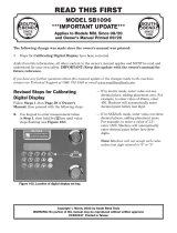
2. Description
2
1
3
4 5 6 4
8
9
7
1 Move lever to set the positions
"Tool open" and "Tool in work
position"
2 Suspension eyelet
3 Guide rail
4 Supporting roller
5 Driver roller 30°
6 Driver roller 75°
7 Roller, horizontal
8 Handle
9 On/Off switch
Folding closer F 305-2
Fig. 46684

E574EN_01.DOC Description 5
2.1 Intended use
Warning
Danger of injury!
¾ Only use the machine for the tasks and materials described in
"Intended use".
The TRUMPF F 305-2 lock seam closer is an electrical hand-held
device used for the following applications:
• Closing of Pittsburgh lock joints on correspondingly pre-
machined workpieces, e.g. ventilation ducts, housings,
containers, etc.
• Machining of all lock seam elevations.
• Closing of the lock seams on straight or curved contours.
• Automatic adjustment to the sheet thickness.
2.2 Technical data of the F 305-2
Other countries USA
Values Values Values Values
Voltage 230 V 120 V 110 V 120 V
Frequency 50/60 Hz 50/60 Hz 50 Hz 50/60 Hz
Material tensile
strength
400 N/mm²
0.45-0.75
mm
0.45-0.75
mm
0.45-0.75
mm
26-22 GA
0.018-0.029
in
Working speed 4-7 m/min 4-7 m/min 4-7 m/min 13-23 ft/min
Nominal power
consumption
500 W 500 W 500 W 500 W
Idle speed n0 160/min 160/min 160/min 160/min
Weight 5.2 kg 5.2 kg 5.2 kg 11.5 lbs
Protective
insulation
Class II Class II Class II Class II
Technical data
Noise and vibration Measured values according to
EN 60745
A-class sound pressure level Typically 81 dB (A)
A-class acoustic power level Typically 85 dB (A)
Hand-arm vibration Typically less than or equal to
2.5 m/s²
Measured noise and vibration values
Note
The measured values specified above may be exceeded while
working.
Table 1
Table 2

6 Description E574EN_01.DOC
Sheet thickness range
[mm] [Gauge]
Height of flange
0.45 - 0.75 26-22
B Height of flange
5 mm/0.197 in
Note
The lock seam quality depends essentially on the height of the
flange B. If B is too small, then the lock seam cannot be properly
closed.
2 3 4
1
1
6 57
1 Supporting roller
2 Driven roller for the first forming
stage (30°)
3 Driven roller for the second
forming stage (75°)
4 Horizontal roller for the third
forming stage (90°)
5 Driven roller for the second
forming stage (75°)
6 Driven roller for the first forming
stage (30°)
7 Guide rail
View of the machine from below: roller arrangement
"Pittsburgh lock seam"
geometry
Table 3
Roller arrangement
Fig. 46685

E574EN_01.DOC Description 7
30° 75° 90°
12 3
1 First stage
2 Second stage
3 Third stage
Folding process
Note
The reforming of the of the takes place in three stages.
Folding process sequence
Fig. 13416

8 Setting work E574EN_01.DOC
3. Setting work
3.1 Setting the tool
The clearance between the rollers and the guide rails can be
locked into place in two positions in order to be able to place the
machine at the desired position of the channel (and) to be able to
remove it from the machining position at the end of the channel:
• Lever (1) in position against the direction of feed: Tool open.
• Move lever (1) in direction of feed in end position: Tool in work
position.
1 Adjustment lever
Tool open
1 Adjustment lever
Tool in work position
Note
No adjustment for sheet thickness is required because the
machine automatically adjusts itself to the sheet thickness.
Tool open
Fig. 46686
Tool in work position
Fig. 46687

E574EN_01.DOC Operation 9
4. Operation
Caution
Damage to property due to high power-supply voltage!
Motor damage
¾ Check the power supply voltage. The power supply voltage
must correspond to the information on the type plate of the
machine.
Warning
Danger of injury due to improper handling!
¾ Make sure the machine is in a stable position when operating
it.
¾ Never touch the tool while the machine is running.
¾ Always operate the machine away from your body.
¾ Do not operate the machine above your head.
4.1 Working with the F 305-2
Move the On/Off switch downwards.
In order to improve work results, lightly oil the rollers or the tool
with universal oil (Order No.138648).
Depending on the construction type of the channel to be machined,
a distinction is made between two possible ways of commencing
work:
• Channel open.
• Flange at the beginning of the channel.
Switching on the F 305-2
Operating the F 305-2

10 Operation E574EN_01.DOC
Bevel the web at the beginning of the channel approximately 30°
for a length of approximately 5 mm.
30°
BP
~ 5 mm
A
A Bevelling for the placement of
the machine
B Flange
P Tacking
Lock seam preparation
Channel open
Lock seam preparation
Fig. 13411

E574EN_01.DOC Operation 11
1
V
V Advance direction 1 Lever
1. Move lever (1) in end position in direction of feed (tool in work
position).
2. Switch on machine and place against the beginning of the
channel.
The curved guide rail ensures a simple placement of the
machine at the beginning of the machining process.
3. The machine is drawn through the driving rollers in the feed
direction, meaning that lock seam closure takes place.
Fig. 13415

12 Operation E574EN_01.DOC
1
Suspension lug preformed to
approximately 80 mm
Length preformed to 30°
1 Preformed suspension lug
The machine cannot be placed up against the beginning of the
channel.
Preparation of the channel so that the machine can be brought into
position.
1. Move lever (1) into position against the direction of feed (Tool
open).
2. Set machine up against desired (prepared) position on the
channel.
3. Position lever (1) in direction of feed. (Tool in work position).
The working direction (direction of feed) of the machine is
determined by its design.
4. Switch on the machine.
5. Close the lock seam.
6. Move lever (1) into "tool open" position.
7. Switch off machine and remove from the machining position.
Note
A minor refinishing operation (length approximately 130 mm) must
be carried out manually at the end of the channel following the use
of the lock seam closer.
¾ Move the On/Off switch upwards.
Flange at the beginning of
the channel
Fig. 18183
Switching off the F 305-2

E574EN_01.DOC Maintenance 13
5. Maintenance
Warning
Danger of injury due to the improper conduction of repair
work!
Machine does not work properly.
¾ Repair work may only be carried out by a qualified specialist.
Maintenance point Procedure and interval Recommended lubricant Lubricant order
no.
Guide rail and driving
pinion
Clean with a steel brush and
apply a light coating of oil every
10 operating hours
Universal oil 0138648
Gearbox and gear head
(2)
After 300 operating hours,
arrange for a trained specialist to
relubricate or to replace the
lubricating grease.
Lubricating grease "G1" 0139440
Ventilation slots Clean as needed - -
Maintenance points and maintenance intervals
5.1 Replacing carbon brushes
The motor comes to a standstill whenever the carbon brushes are
worn out.
¾ Have the carbon brushes checked and replaced as required by
a qualified specialist.
Note
Only use original replacement parts and observe the information
on the rating plate.
Table 4

14 Maintenance E574EN_01.DOC
5.2 Tightening screws with turning
moment
If parts of the machine are disassembled, be sure that the screws
and nuts are tightened with the right torque when the machine is
reassembled.
1
3
24
6
5
1 Roller (30°)
2 Roller (75°)
3 Driver roller (30°)
4 Driver roller (75°)
5 Slotted nut
6 Cylindrical pin 5 m 6x24
DIN 6325
View of the seam locker F 305 from below; the guide
rail and the supporting rollers have been
disassembled.
No. Components Torque Threaded nut
retention
1 Roller (30°) 24 Nm Loctite 262
2 Roller (75°) 24 Nm Loctite 262
3 Driver roller (30°) 24 Nm -
4 Driver roller (75°) 24 Nm -
5 Slotted nut 6 Nm1 Loctite 262
6 Cylindrical pin 5 m 6x24
DIN 6325
- -
1 Locking mechanism must be closed.
Fig. 46688
Table 5

E574EN_01.DOC Original accessories and wearing parts 15
6. Original accessories and wearing parts
Designation Supplied
original
acces-
sories
Wearing
parts
Op-
tions
Order
no.
Guide rail + + 920881
Driver roller 30° + + 145769
Driver roller 75° + + 135478
Roller (horizontal) + + 135791
Suspension eyelet + 107666
Allen key DIN 911-4 + 067849
Universal oil (0.1 liter) + 138648
Case + 982582
Operating manual + 1369682
Safety information (red
document), other countries
+ 125699
Safety information (red
document), USA
+ 1239438
Original accessories, wearing parts and optional items
To ensure the correct and fast delivery of original parts and
wearing parts:
1. Specify the order number.
2. Enter further order data:
– Voltage data
– Quantity
– Machine type
3. Provide complete shipping information:
– Correct address
– Desired delivery type (e.g. air mail, courier, express mail,
ordinary freight, parcel post).
4. Send the order to your TRUMPF representative. Refer to the
address list at the end of the document for TRUMPF service
addresses.
Table 6
Ordering wearing parts

16 Original accessories and wearing parts E574EN_01.DOC
/