ESAB ESABMig C420 User manual
- Category
- Welding System
- Type
- User manual
This manual is also suitable for

0349 300 041 Valid for serial no. 237–xxx–xxxx 030410
ESABMig C420
ESABMig C420s
Service manual

– 2 –TOCe
READ THIS FIRST 4. . . . . . . . . . . . . . . . . . . . . . . . . . . . . . . . . . . . . . . . . . . . . . . . . . . . . . . . . . . . . . . . .
INTRODUCTION 4. . . . . . . . . . . . . . . . . . . . . . . . . . . . . . . . . . . . . . . . . . . . . . . . . . . . . . . . . . . . . . . . . . .
TECHNICAL DATA 4. . . . . . . . . . . . . . . . . . . . . . . . . . . . . . . . . . . . . . . . . . . . . . . . . . . . . . . . . . . . . . . . .
WIRING DIAGRAM 6. . . . . . . . . . . . . . . . . . . . . . . . . . . . . . . . . . . . . . . . . . . . . . . . . . . . . . . . . . . . . . . . .
Component description 6. . . . . . . . . . . . . . . . . . . . . . . . . . . . . . . . . . . . . . . . . . . . . . . . . . . . . . . . . .
ESABMig C420/C420w 8. . . . . . . . . . . . . . . . . . . . . . . . . . . . . . . . . . . . . . . . . . . . . . . . . . . . . . . . . . .
ESABMig C420/C420w 9. . . . . . . . . . . . . . . . . . . . . . . . . . . . . . . . . . . . . . . . . . . . . . . . . . . . . . . . . . .
ESABMig C420s/C420sw 10. . . . . . . . . . . . . . . . . . . . . . . . . . . . . . . . . . . . . . . . . . . . . . . . . . . . . . . . .
ESABMig C420s/C420sw 11. . . . . . . . . . . . . . . . . . . . . . . . . . . . . . . . . . . . . . . . . . . . . . . . . . . . . . . . .
DESCRIPTION OF OPERATION 12. . . . . . . . . . . . . . . . . . . . . . . . . . . . . . . . . . . . . . . . . . . . . . . . . . . . .
AP1 Control board (for C420w/C420) 12. . . . . . . . . . . . . . . . . . . . . . . . . . . . . . . . . . . . . . . . . . . . . .
AP1:1 Power supply 12. . . . . . . . . . . . . . . . . . . . . . . . . . . . . . . . . . . . . . . . . . . . . . . . . . . . . . . . . . . . . .
AP1:2 Activation, contactor 12. . . . . . . . . . . . . . . . . . . . . . . . . . . . . . . . . . . . . . . . . . . . . . . . . . . . . . . .
AP1:3 Activation, gas valve 13. . . . . . . . . . . . . . . . . . . . . . . . . . . . . . . . . . . . . . . . . . . . . . . . . . . . . . . .
AP1:4 2–stroke / 4–stroke 13. . . . . . . . . . . . . . . . . . . . . . . . . . . . . . . . . . . . . . . . . . . . . . . . . . . . . . . . .
AP1:5 Burn–back time 14. . . . . . . . . . . . . . . . . . . . . . . . . . . . . . . . . . . . . . . . . . . . . . . . . . . . . . . . . . . .
AP1:6 Wire feed speed 14. . . . . . . . . . . . . . . . . . . . . . . . . . . . . . . . . . . . . . . . . . . . . . . . . . . . . . . . . . . .
AP1:7 Motor driving / braking 15. . . . . . . . . . . . . . . . . . . . . . . . . . . . . . . . . . . . . . . . . . . . . . . . . . . . . .
AP1:8 Tachometer input 16. . . . . . . . . . . . . . . . . . . . . . . . . . . . . . . . . . . . . . . . . . . . . . . . . . . . . . . . . . .
AP1:9 Creep start, Current relay 16. . . . . . . . . . . . . . . . . . . . . . . . . . . . . . . . . . . . . . . . . . . . . . . . . . . .
AP1:10 Start / Stop 17. . . . . . . . . . . . . . . . . . . . . . . . . . . . . . . . . . . . . . . . . . . . . . . . . . . . . . . . . . . . . . .
AP1:11 Processor 17. . . . . . . . . . . . . . . . . . . . . . . . . . . . . . . . . . . . . . . . . . . . . . . . . . . . . . . . . . . . . . . .
AP1 Component positions (0486 205 886) 18. . . . . . . . . . . . . . . . . . . . . . . . . . . . . . . . . . . . . . . . . . .
AP1 Component positions (0486 205 882) 19. . . . . . . . . . . . . . . . . . . . . . . . . . . . . . . . . . . . . . . . . . .
AP2 Digital instrument (option for C420w/C420) 20. . . . . . . . . . . . . . . . . . . . . . . . . . . . . . . . . . .
AP2:1 Calibration and voltage correction 20. . . . . . . . . . . . . . . . . . . . . . . . . . . . . . . . . . . . . . . . . . . . .
AP2:2 Connections to the digital instrument 21. . . . . . . . . . . . . . . . . . . . . . . . . . . . . . . . . . . . . . . . . .
AP1 (0349 303 176), AP2 (0349 303 193) control boards
(for C420s/C420sw) 22. . . . . . . . . . . . . . . . . . . . . . . . . . . . . . . . . . . . . . . . . . . . . . . . . . . . . . . . . . . . . .
AP1:1 Power suply 22. . . . . . . . . . . . . . . . . . . . . . . . . . . . . . . . . . . . . . . . . . . . . . . . . . . . . . . . . . . . . . .
AP1:2 Start / stop 22. . . . . . . . . . . . . . . . . . . . . . . . . . . . . . . . . . . . . . . . . . . . . . . . . . . . . . . . . . . . . . . .
AP1:3 Welding current detection 23. . . . . . . . . . . . . . . . . . . . . . . . . . . . . . . . . . . . . . . . . . . . . . . . . . . .
AP1:4 Welding parameter setting 23. . . . . . . . . . . . . . . . . . . . . . . . . . . . . . . . . . . . . . . . . . . . . . . . . . .
AP1:5 Motor driving / braking 24. . . . . . . . . . . . . . . . . . . . . . . . . . . . . . . . . . . . . . . . . . . . . . . . . . . . . .
AP1:6 Burnback time, contactor, gas valve 25. . . . . . . . . . . . . . . . . . . . . . . . . . . . . . . . . . . . . . . . . . .
AP1:7 2–stroke / motor test (inching) / 4–stroke 26. . . . . . . . . . . . . . . . . . . . . . . . . . . . . . . . . . . . . .
AP1:8, AP2:1 Measuring and displaying of welding parameters 26. . . . . . . . . . . . . . . . . . . . . . . . .
AP1:9 Synergy control presets and indications 28. . . . . . . . . . . . . . . . . . . . . . . . . . . . . . . . . . . .
AP3 Control board 30. . . . . . . . . . . . . . . . . . . . . . . . . . . . . . . . . . . . . . . . . . . . . . . . . . . . . . . . . . . . . .
AP3:1 Start 30. . . . . . . . . . . . . . . . . . . . . . . . . . . . . . . . . . . . . . . . . . . . . . . . . . . . . . . . . . . . . . . . . . . . . .
AP3:2 Overheating protection 30. . . . . . . . . . . . . . . . . . . . . . . . . . . . . . . . . . . . . . . . . . . . . . . . . . . . . .
AP3:3 Water connection 31. . . . . . . . . . . . . . . . . . . . . . . . . . . . . . . . . . . . . . . . . . . . . . . . . . . . . . . . . . .
AP3:4 Water flow guard (ESABMig C420w – optionally) 31. . . . . . . . . . . . . . . . . . . . . . . . . . . . . . .
AP3:5 Idle mode 31. . . . . . . . . . . . . . . . . . . . . . . . . . . . . . . . . . . . . . . . . . . . . . . . . . . . . . . . . . . . . . . . .
AP3 Component positions 31. . . . . . . . . . . . . . . . . . . . . . . . . . . . . . . . . . . . . . . . . . . . . . . . . . . . . . . . .
SERVICE INSTRUCTIONS 32. . . . . . . . . . . . . . . . . . . . . . . . . . . . . . . . . . . . . . . . . . . . . . . . . . . . . . . . . .
What is ESD? 32. . . . . . . . . . . . . . . . . . . . . . . . . . . . . . . . . . . . . . . . . . . . . . . . . . . . . . . . . . . . . . . . . . .
INSTRUCTIONS 33. . . . . . . . . . . . . . . . . . . . . . . . . . . . . . . . . . . . . . . . . . . . . . . . . . . . . . . . . . . . . . . . . . .
SAFETY 33. . . . . . . . . . . . . . . . . . . . . . . . . . . . . . . . . . . . . . . . . . . . . . . . . . . . . . . . . . . . . . . . . . . . . . . .
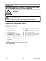
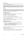
INSTALLATION 34. . . . . . . . . . . . . . . . . . . . . . . . . . . . . . . . . . . . . . . . . . . . . . . . . . . . . . . . . . . . . . . . . .
Placing 34. . . . . . . . . . . . . . . . . . . . . . . . . . . . . . . . . . . . . . . . . . . . . . . . . . . . . . . . . . . . . . . . . . . . . . . . .
Assembly of components 34. . . . . . . . . . . . . . . . . . . . . . . . . . . . . . . . . . . . . . . . . . . . . . . . . . . . . . . .
Electrical installation 35. . . . . . . . . . . . . . . . . . . . . . . . . . . . . . . . . . . . . . . . . . . . . . . . . . . . . . . . . . . .
Mains power supply 35. . . . . . . . . . . . . . . . . . . . . . . . . . . . . . . . . . . . . . . . . . . . . . . . . . . . . . . . . . . . .

– 3 –TOCe
OPERATION 36. . . . . . . . . . . . . . . . . . . . . . . . . . . . . . . . . . . . . . . . . . . . . . . . . . . . . . . . . . . . . . . . . . . . . . .
CONNECTIONS AND CONTROL DEVICES 36. . . . . . . . . . . . . . . . . . . . . . . . . . . . . . . . . . . . . . . . .
ESABMig C420w/C420 36. . . . . . . . . . . . . . . . . . . . . . . . . . . . . . . . . . . . . . . . . . . . . . . . . . . . . . . . . . .
ESABMig C420sw/C420s 37. . . . . . . . . . . . . . . . . . . . . . . . . . . . . . . . . . . . . . . . . . . . . . . . . . . . . . . . .
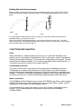
Setting the wire feed pressure 39. . . . . . . . . . . . . . . . . . . . . . . . . . . . . . . . . . . . . . . . . . . . . . . . . . .
FUNCTIONS EXPLANATION 39. . . . . . . . . . . . . . . . . . . . . . . . . . . . . . . . . . . . . . . . . . . . . . . . . . . . . .
ESABMig C420w/C420 40. . . . . . . . . . . . . . . . . . . . . . . . . . . . . . . . . . . . . . . . . . . . . . . . . . . . . . . . . . .
ESABMig C420sw/C420s 40. . . . . . . . . . . . . . . . . . . . . . . . . . . . . . . . . . . . . . . . . . . . . . . . . . . . . . . . .
MAINTENANCE 42. . . . . . . . . . . . . . . . . . . . . . . . . . . . . . . . . . . . . . . . . . . . . . . . . . . . . . . . . . . . . . . . . . . .
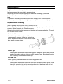
Inspection and cleaning 42. . . . . . . . . . . . . . . . . . . . . . . . . . . . . . . . . . . . . . . . . . . . . . . . . . . . . . . . .
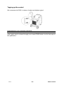
Topping up the coolant 43. . . . . . . . . . . . . . . . . . . . . . . . . . . . . . . . . . . . . . . . . . . . . . . . . . . . . . . . . .
ORDERING OF SPARE PARTS 43. . . . . . . . . . . . . . . . . . . . . . . . . . . . . . . . . . . . . . . . . . . . . . . . . . . . . .
NOTES 44. . . . . . . . . . . . . . . . . . . . . . . . . . . . . . . . . . . . . . . . . . . . . . . . . . . . . . . . . . . . . . . . . . . . . . . . . . .

Edition 030410
– 4 –
doce1
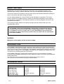
READ THIS FIRST
Maintenance and repair work should be performed by an experienced person, and
electrical work only by a trained electrician. Use only recommended replacement parts.
This service manual is intended for use by technicians with electrical/electronic training for
help in connection with fault–tracing and repair.
Use the wiring diagram as a form of index for the description of operation. The circuit
board is divided into numbered blocks, which are described individually in more detail in
the description of operation. All component names in the wiring diagram are listed in the
component description.
This manual contains details of all design changes that have been made up to and
including March 2003.
The ESABMig C420w/C420 and ESABMig C420sw/C420s are designed and tested in
accordance with international and European standard IEC/EN 60974–1 and EN 50199.
On completion of service or repair work, it is the responsibility of the person(s) etc.
performing the work to ensure that the product does not depart from the requirements
of the above standard.
WARNING
Many parts of the power unit are at mains voltage.
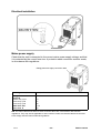
INTRODUCTION
The ESABMig C420w/C420sw are step–controlled compact welding power units incorporating wire
feed mechanism intended for MIG/MAG welding with solid wires of steel, stainless steel or aluminium,
and cored wires with or without shielding gas. The ESABMig C420w/420sw are equipped with cooling
liquid system for welding torch. The ESABMig C420/420s are not equipped with cooling system and
can operate only with appropriate gas cooled torches.
The ESABMig C420w/420 is equipped with standard control unit (manual setting of all welding
parameters) and ESABMig C420sw/420s contains additional synergy control facility (preprogrammed
welding parameters).
The power units are fan–cooled and equipped with thermal overload protection.
The machines can be fitted with a flow guard (C420sw/C420w).
TECHNICAL DATA
ESABMig C420/C420w ESABMig C420s/C420sw
Voltage 400–415V, 3~50/60Hz 400–415V, 3~50/60Hz
Permissible load
at100 % duty cycle 315 A/30V 315 A/30V
at 60 % duty cycle 400 A/34V 400 A/34V
at 50 % duty cycle 420 A/35V 420 A/35V
Setting range (DC) 50A/16,5V–420A/35V 50A/16,5V–420A/35V
Open circuit voltage 14–47V 14–47V

Edition 030410
– 5 –doce1
Open circuit power 520W 520W
with cooling unit 730W 730W
Efficiency at max current 77% 77%
Power factor at max current 0,92 0,92
Control voltage 42V, 50/60Hz 42V, 50/60Hz
Wire feed speed 1,9 – 25,0m/min 1,6 – 25,0m/min
Burnback time 0 – 0,5s 0 – 0,35s
Creep start OFF / ON ON
2/4 stroke 2 / 4 2 / 4 /
Welding gun connection EURO EURO
Max diameter of wire bobbin 300mm 300mm
Wire dimension range 0,6 – 1,6mm 0,6 – 1,6mm
Dimensions lxwxh 935 x 640 x 800mm 935 x 640 x 800mm
Weight 209kg 209kg
with cooling unit 217kg 217kg
Operating temperature –10 to +40
o
C –10 to +40
o
C
Enclosure class IP 23 IP 23
Application classification
ESABMig C420/C420w
Voltage 230/400–415/500V 3~50Hz 230/440–460 3~60Hz
Permissible load
at100 % duty cycle 315 A/30V
at 60 % duty cycle 400 A/34V
at 50 % duty cycle 420 A/35V
Setting range (DC) 50A/16,5V–420A/35V
Open circuit voltage 14–47V
Open circuit power 520W
with cooling unit 730W
Efficiency at max current 77%
Power factor at max current 0,92
Control voltage 42V, 50/60Hz
Wire feed speed 1,9 – 25,0m/min
Burnback time 0 – 0,5s
Creep start OFF / ON
2/4 stroke 2 / 4
Welding gun connection EURO
Max diameter of wire bobbin 300mm
Wire dimension range 0,6 – 1,6mm
Dimensions lxwxh 935 x 640 x 800mm
Weight 209kg
with cooling unit 217kg
Operating temperature –10 to +40
o
C
Enclosure class IP 23
Application classification

Edition 030410
– 6 –
doce1
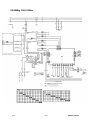
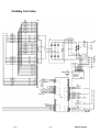
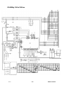
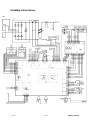
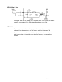
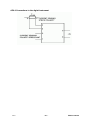
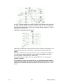
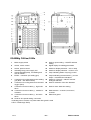
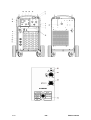
WIRING DIAGRAM
Component description
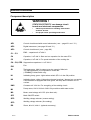
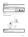
WARNING !
STATIC ELECTRICITY can damage circuit
boards and electronic components.
S Observe precautions for handling electrostatic
sensitive devices.
S Use proper static–proof bags and boxes.
ESD
AP1
Control circuit board with control electronics ( see – page XX and YY ).
AP2
Digital instrument ( see page XX and YY ).
AP3
Control circuit board ( see – page XX).
C1 – C3
EMC – capacitors 2 uF 450 V.
C4
Capacitor, 3 uF 400 V. Start and run capacitor for fan motor EV1.
C5
Capacitor, 6 uF 400 V. For speed reduction of the cooling fan.
C6 – C8, CES
Suppression capacitors 0.1 uF 250 V.
EV1
Fan.
G1
Tachogenerator, 660 Hz output at a wire speed of 25m/min.
The tachogenerator is incorporated in motor M2
( ESABMig C420w/C420 only).
H1
Indicating lamp, green. Lights when switch QF1 is in the ON position.
H2
Indicating lamp, yellow. Lights when thermal overload ( thermal cut–out active).
If the machine is equipped with flow guard, the lamp also indicates loss of
coolant.
KM1
Contactor 42 V 50 Hz. For energising of the welding circuit.
M1
Pump motor, 230 V 50 Hz 0.2 kW. Only machines with water cooler.
M2
Motor, rated voltage 42 V DC (wire feed unit).
QF1
Main ON/OFF switch.
QF2
Welding voltage selector (coarse setting).
QF3
Welding voltage selector (fine setting).
RS
Shunt, 60 mV / 400 A (optional accessory).

Edition 030410
– 7 –doce1
S2
ELP switch – on the cooling water outlet, activates pump M1.
Only in machines with water cooler.
SL1
Flow guard (optional accessory; only in machines with water cooler.).
ST1
Thermal switch – overheating protection, in the inductor L1 ( NC, 120
o
C).
ST2
Thermal switch – overheating protection, on the bridge V1 ( NC, 120
o
C).
ST3
Thermal switch – change–over the speed of the fan motor EV1 (NO, 80
o
C).
The switch opens when the machine temperature falls to 60
o
C.
TC1
Control power supply transformer.
TC2
Transformer for CO2 heater (optional accessory).
TM1
Main transformer.
V1
Diode bridge (3ph.).
V2
Diode bridge (1ph.; ESABMig C420sw/C420s only).
XB1
EURO–Connector, for welding gun connection.
XB2 – XB4
Welding current socket, single––pole (return current wire).
XT1
9 pole/ 3 pole – terminal block
(machine with/without water cooler–respectively).
XT2
Auxilary 1 pole connector.
XT3
2 pole terminal block (optional accessory).
XTP
Terminal block for polarity reversing .

Edition 030410
– 8 –
doce1
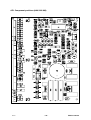
ESABMig C420/C420w

Edition 030410
– 9 –doce1
ESABMig C420/C420w

Edition 030410
– 10 –
doce1
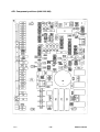
ESABMig C420s/C420sw

Edition 030410
– 11 –doce1
ESABMig C420s/C420sw

Edition 030410
– 12 –
doce1
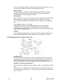
DESCRIPTION OF OPERATION
This description of operation describes the function of circuit boards and other components
in the power unit. It is divided into sections, numbered to correspond to the circuit board
numbers and divisions into function blocks.
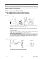
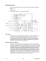
AP1 Control board (for C420w/C420)
Note: AP1 – 0486 205 882 only for machines manufactured till May 2003
Note: AP1 – 0486 205 886 only for machines manufactured after May 2003
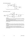
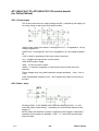
AP1:1 Power supply
The wire feed unit receives 42 V from the control power supply transformer in
the welding power unit via relay contact on AP3.
42 V AC is supplied to the welding gun trigger switch, the gas valve and the
contactor.
DC power supplies
Diodes D30 – D33 rectify the 42 V supply to 60 V. Capacitor C61 smooths the
supply, which is then used to power the wire feeder motor.
Transistor Q2 is a pre–regulator that drops the voltage from 60 V to 20 V. Q2 is
current–limited to about 200 mA.
VR1 and VR2 are voltage regulators, producing 5 V and 15 V respectively. The
circuit board’s microprocessor monitors the voltages. If the 15 V supply falls
below 13 V, the wire feed unit is stopped.
AP1:2 Activation, contactor
The start signal is connected to contactor KM1.

Edition 030410
– 13 –doce1
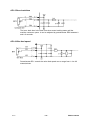
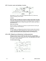
AP1:3 Activation, gas valve
The gas valve is connected to connectors F04 and F05.
AP1:4 2–stroke / 4–stroke
2–stroke
When switch SP2 is open, 2–stroke control mode is selected. This means that
closing the welding gun trigger switch starts the wire feed motor, opens the gas
valve and closes the power unit contactor.
Releasing the switch stops the motor, releases the contactor and closes the
gas valve. If burn–back time is operative, welding ceases after the burn–back
time has elapsed.
4–stroke
When switch SP21 is closed, 4–stroke control mode is selected. This means
that first closure of the trigger switch operates the gas valve, with the wire feed
motor starting, and the power unit contactor operating, when the trigger switch
is released.
Closing the trigger switch for the second time stops the motor and
de–energises the contactor in the power unit. Releasing the switch closes the
gas valve. If burn–back time is operative, welding ceases after the burn–back
time has elapsed.

Edition 030410
– 14 –
doce1
AP1:5 Burn–back time
The burn–back time is the time from when motor braking starts until the
machine contactor opens. It can be adjusted by potentiometer RP2 between 0
and 0.5 seconds.
AP1:6 Wire feed speed
Potentiometer RP1 controls the wire feed speed over a range from 1.9 to 25
metres/minute.

Edition 030410
– 15 –doce1
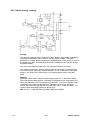
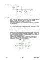
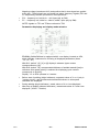
AP1:7 Motor driving / braking
Driving
The motor is powered by the smoothed +60 V supply. Pulse width modulation,
controlled by transistor Q3, is used to vary the motor voltage. The pulse
frequency is 12 kHz, and the maximum conducting time of the pulses is 97% of
the pulse cycle time. Freewheeling diode D11 maintains motor current during
the pulse breaks.
At a drive roller speed of 266 r/min, the wire feed speed is 25 m/min.
The voltage drop across resistor R92 provides a signal that is proportional to
the motor current. When the current exceeds 15.4 A, IC6:2 turns off the gate
pulse to Q3. When the current drops, Q3 conducts again at the next gate
pulse.
Braking
When the motor starts, capacitor C60 charges up to 15 V, with zener diode
D20 limiting the voltage across it. Braking is activated by the optocoupler IC3.
When the transistor in IC3 is turned on by the LED, 15 V from capacitor C60 is
connected to the gate of transistor Q4. Transistor Q4 turns on and short
circuits the motor through the resistors R85–R87 (AP1 – 0486 205 886). The
resistors limit the braking current to about 20 A.
NB: On AP1 – 0486 205 882 only R86 & R86 are installed.

Edition 030410
– 16 –
doce1
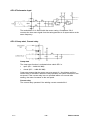
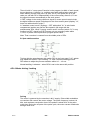
AP1:8 Tachometer input
The tachometer G1 is fitted inside the motor casing. Comparator IC5;2
converts the sine wave signal from the tachogenerator to a square wave at the
same frequency.
AP1:9 Creep start, Current relay
Creep start
The creep start function is activated when switch SP1 is:
S open (AP1 – 0486 205 886)
S closed (AP1 – 0486 205 882)
Creep start means that the motor runs at a speed of 1.9 m/minute until the
current relay is activated. When the relay operates, the speed increases to the
set speed. If the current relay has not operated within one second after
starting, the motor increases to the set speed.
Current relay
The current relay operates if the welding current exceeds 20 A.

Edition 030410
– 17 –doce1
AP1:10 Start / Stop
The trigger switch in the welding gun is supplied at 42 V AC. Closing the switch
energises optocoupler IC10, pulling down the voltage across C46.
AP1:11 Processor
The processor stores the machine program. It monitors the power supply
voltages: if the voltages drop to too low a level, wire feed is stopped, as
described in section AP1:1 above.
The processor also monitors speed. If the wire speed deviates from the set
value by more than 1.5 m/min for more than five seconds, wire feed will be
stopped.

Edition 030410
– 18 –
doce1
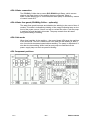
AP1 Component positions (0486 205 886)

Edition 030410
– 19 –doce1
AP1 Component positions (0486 205 882)

Edition 030410
– 20 –
doce1
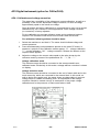
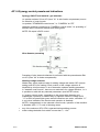
AP2 Digital instrument (option for C420w/C420)
AP2:1 Calibration and voltage correction
The meter has a possibility of the voltage and current calibration, as well as a
possibility of the current–dependant voltage correction, to show a voltage
approximately equal to the actual arc voltage.
Since all meters are factory calibrated it is recommended to carry out a second
calibration only if it’s needed. In most applications a zero voltage correction
(no correction) is factory adjusted.
For the calibration an accurate reference meter and a resistance load are
required. The resistance load should force at least 100A current flow.
For calibration following actions should be done:
1 Switch the machine on and load it. The meter should indicate voltage and
current presence.
2 Press simultaneously both pushbuttons placed on the meter PC board. In
sequence, symbols of the calibration modes appear: ”U” – voltage calibration,
”I” – current calibration, ”dU” – voltage correction. Release the buttons as the
required mode appears.
3 Adjust the voltage or the current value equal to the value shown by the
reference meter by means of the pushbuttons: S1 – ”+”, S2 – ”–”.
Voltage calibration mode
The reference meter should be connected to the same potentials as a
calibrated meter. Exclusively in this mode a voltage without correction is shown
on display.
Voltage reduction mode
The reference meter should be connected to the end of mass cable and to the
torch current tip, which are connected to the external load. In this mode, as
well as during the regular work, the meter shows a voltage taking in account
voltage drops on cables and welding torch. An adjustment of the voltage
correction should be carried out only in assumption of the proper voltage
calibration and in the presence of load current above 100A.
Page is loading ...
Page is loading ...
Page is loading ...
Page is loading ...
Page is loading ...
Page is loading ...
Page is loading ...
Page is loading ...
Page is loading ...
Page is loading ...
Page is loading ...
Page is loading ...
Page is loading ...
Page is loading ...
Page is loading ...
Page is loading ...
Page is loading ...
Page is loading ...
Page is loading ...
Page is loading ...
Page is loading ...
Page is loading ...
Page is loading ...
Page is loading ...
Page is loading ...
Page is loading ...
-
 1
1
-
 2
2
-
 3
3
-
 4
4
-
 5
5
-
 6
6
-
 7
7
-
 8
8
-
 9
9
-
 10
10
-
 11
11
-
 12
12
-
 13
13
-
 14
14
-
 15
15
-
 16
16
-
 17
17
-
 18
18
-
 19
19
-
 20
20
-
 21
21
-
 22
22
-
 23
23
-
 24
24
-
 25
25
-
 26
26
-
 27
27
-
 28
28
-
 29
29
-
 30
30
-
 31
31
-
 32
32
-
 33
33
-
 34
34
-
 35
35
-
 36
36
-
 37
37
-
 38
38
-
 39
39
-
 40
40
-
 41
41
-
 42
42
-
 43
43
-
 44
44
-
 45
45
-
 46
46


ESAB ESABMig C420 User manual
- Category
- Welding System
- Type
- User manual
- This manual is also suitable for
Ask a question and I''ll find the answer in the document
Finding information in a document is now easier with AI
Related papers
-
ESAB ESABMig C420 User manual
-
-
-
-
ESAB Feed 30, Feed 30w User manual
-
-
ESAB ESABMig 325 User manual
-
-
-
Other documents
-
Abtus CAT-GA111R User Operating Manual
-
SmartWitness AP1 EMEA Installation guide
-
NAD Stereo Amplifier C420 User manual
-
 astra telematics AT100 Quick Installation Manual
-
Erreka VIVO-D103 Quick Installation And Programming Manual
-
PAC RP4-CH11 Tech Brief
-
Digisol DG-WM2005SI Quick Installation Guide
-
Sensata AP1 Video Telematics User guide
-
ETS 930D & 930D-FTS User manual
-
Zip Aquapoint III AP3/15 Installation Instructions Manual
