Page is loading ...

Remote Automation Solutions
Form A6248
Part Number D301345X012
June 2017
Gas Chromatograph Software Interface User
Manual (for FloBoss™ 107)

Gas Chromatograph Software Interface User Manual (for FB107)
ii Revised June-2017
Revision Tracking Sheet
June 2017
This manual may be revised periodically to incorporate new or updated information. The revision date
of each page appears at the bottom of the page opposite the page number. A change in revision date
to any page also changes the date of the manual that appears on the front cover. Listed below is the
revision date of each page (if applicable):
Page
Revision
All pages
June-2017
All pages
February-2010
All pages
February-2009
All pages
October-2008
All pages
September-2008
Page 5, 7
February-2008
Initial Release
January-2008

Gas Chromatograph Software Interface User Manual (for FB107)
Revised June-2017 Contents iii
Contents
Chapter 1 – Introduction 1
1.1 Scope and Organization ..................................................................................................................... 1
1.2 Product Overview ............................................................................................................................... 1
1.2.1 Communications Wiring ......................................................................................................... 2
1.2.2 Auto-configure ........................................................................................................................ 3
1.2.3 Validating GC Data ................................................................................................................ 5
1.3 Program Requirements ...................................................................................................................... 7
1.3.1 License Key ............................................................................................................................ 7
Chapter 2 – Installation 9
2.1 Installing the License Key .................................................................................................................. 9
2.2 Downloading the Program ................................................................................................................ 10
Chapter 3 – Configuration 15
3.1 GC Interface Screen ........................................................................................................................ 16
3.2 GC Configuration Screen ................................................................................................................. 19
3.3 GC Stream Data Screen .................................................................................................................. 22
3.4 Meter Setup Screen ......................................................................................................................... 26
3.5 Saving the Configuration .................................................................................................................. 28
Chapter 4 – Reference 31
4.1 Point Type 22/25: GC User Program Configuration and Status ...................................................... 32
4.2 Point Type 23/26: GC User C Program Stream Data ...................................................................... 37

Gas Chromatograph Software Interface User Manual (for FB107)
iv Contents Revised June-2017
[This page is intentionally left blank.]

Gas Chromatograph Software Interface User Manual (for FB107)
Revised June-2017 Introduction 1
Chapter 1 – Introduction
Caution
When implementing control using this product, observe best industry
practices as suggested by applicable and appropriate environmental,
health, and safety organizations. While this product can be used as a
safety component in a system, it is NOT intended or designed to be the
ONLY safety mechanism in that system.
This chapter describes the structure of this manual and presents an
overview of the Gas Chromatograph Software Interface for the
FloBoss™ 107.
1.1 Scope and Organization
This document serves as the user manual for the Gas Chromatograph
Software Interface, which is intended for use in a FloBoss 107 (FB107).
This manual describes how to download, install, and configure the Gas
Chromatograph Software Interface user program (referred to as the “GC
Interface program” or “the program” throughout the rest of this manual).
You access and configure this program using ROCLINK™ 800
Configuration Software (version 2.40 or greater) loaded on a personal
computer (PC) running Windows
®
7 (32 or 64-bit).
The sections in this manual provide information in a sequence
appropriate for first-time users. Once you become familiar with the
procedures and the software running in FB107, the manual becomes a
reference tool.
This manual has the following major sections:
Chapter 1 – Introduction
Chapter 2 – Installation
Chapter 3 – Configuration
Chapter 4 – Reference
This manual assumes that you are familiar with the FB107 and its
configuration. For more information, refer to the following manuals:
FloBoss 107 Flow Manager Instruction Manual (part
D301232X012)
ROCLINK 800 Configuration Software User Manual (for FB107)
(part D301249X012)
1.2 Product Overview
The GC Interface program enables the FB107 to communicate directly
with up to two gas chromatographs (GCs) on the same EIA-232 (RS-
232), EIA-485 (RS-485), or Ethernet communications port. Gas
Chromatographs supported include the Daniel (Danalyzer) and
Rosemount Analytical Models 500, 570, 590, 700, 770 and

Gas Chromatograph Software Interface User Manual (for FB107)
2 Introduction Revised June-2017
1000/1000A. GC controllers supported include the Daniel and
Rosemount Analytical Models 2251, 2255, 2350, 2350A and 2360. The
program communicates directly with the GC using Modbus protocol (in
which the FB107 has Master status). The FB107 polls data from the GC,
validates that data, and updates the appropriate meter run parameters
using that data. The program can poll up to eight GC streams on one GC
or up to a total of ten streams on two GCs.
Note: Using MON 2000 software, you set the Daniel GC
communications port to the SIM 2251 protocol. For all other
parameter configurations, refer to the MON 2000
documentation.
In order to update meter run data in the FB107, you must assign the
streams to a meter run in the FB107’s database. This allows the FB107
to log the gas component data, heating value, and specific gravity and
use these values in volume, mass, and energy calculations.
Note: Two versions of the program are included. Installation and
operation are identical between the two programs, but they use
different point type locations, different display numbers, and are
loaded into different program slots on the FB107.
GCInterface_1.bin loads into user program location 1 and uses
point types 22 and 23. GCInterface_2.bin loads into user
program location 2 and uses point types 25 and 26.
The manual shows installation of GCInterface_1.bin. Load
GCInterface_1.bin unless another user program is currently
installed in user program location 1.
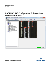
1.2.1 Communications Wiring
The GC must be connected to the communications port on the FB107
with wiring between 16 and 24 AWG. Figure 1 shows the wiring for an
EIA-232 (RS-232) to a Daniel 2350A GC.

Gas Chromatograph Software Interface User Manual (for FB107)
Revised June-2017 Introduction 3
Figure 1-1. Communications Wiring
1.2.2 Auto-configure
The GC Program provides an auto-configure option on the GC Interface
screen (see Figure 3-2). This option enables the program to
automatically configure the communication ports and Modbus
parameters necessary to poll the GC(s). For this option to work,
however, you must first specify a communication port in the Comm
Port # field on the GC Interface screen, specify the maximum number of
streams and Modbus address for each GC in use, and modify the
Modbus register table location, if desired.
When you select Auto-configure on the GC Interface screen, the
program sets the selected communication port parameters to the
following values:
Note: The following communication port parameters are configured if
you are using an RS-232 or RS-485 module only.
Baud Rate:
9600
Data Bits:
8
Stop Bits:
1
Parity:
None
Key-On Delay:
200 mSec
Key-Off Delay:
200 mSec
Port Owner:
Modbus Master
When you select Auto-configure on the GC Interface screen, the
program sets the Modbus configuration parameters for the selected
communications port to the following values:
FB107
EIA-232 (RS-232) Port
Daniel 2350A
Terminals J6 (port 2), J10
(port 3), or J11 (port 4)
Rx
T
x
RTS
DTR
GND
6
5
4
3
2
1
S
IN_2
S
OUT_2
GND

Gas Chromatograph Software Interface User Manual (for FB107)
4 Introduction Revised June-2017
Transmission Mode:
RTU
Byte Order:
MSB First
Event Log Enable
Disabled
Master Starting Request Number:
1
Master Number of Requests:
8
Master Continuous Polling Enable:
Disabled
When you select Auto-configure on the GC Interface screen, the
program automatically configures the Modbus Master Table (using
values in the Comm Port # and Modbus Address fields on the GC
Interface screen) to poll for the following registers in the GC:
3001–3016:
Component IDs, Table 1
3017–3032:
Component IDs, Table 2
3034:
Current Stream
3035:
Mask of Streams associated with Table 1
3045:
Cycle Start Time – minutes
3046:
GC Alarm 1
3047:
GC Alarm 2
3059:
Calibration/Analysis Flag
7001–7016:
Gas Composition Values Mole % Comp 1–16
7033:
BTU (day)
7034:
BTU (saturated)
7035:
Specific Gravity
7036:
Compressibility
7037:
Wobbe Index
7038:
Total Unnormalized Mole %
7039
Total GPM CF
7040–7044
User Defined Calc Values
7070–7084
User Defined Average
9034:
Active Alarm Status
9035:
Unacknowledged Alarm Status
Note: Depending on the GC device, registers 9034 and 9035 may
require a Modbus conversion code to be manually configured.
When you select Auto-configure on the GC Interface screen, the
program sets the Modbus Master Tables for each GC with a valid
address. The first GC’s master table uses the first logical point for the
communications port, and the second GC (if present) uses the second
logical point for its communications port. The actual poll sequence set
for each GC is:
3045–3047

Gas Chromatograph Software Interface User Manual (for FB107)
Revised June-2017 Introduction 5
3001–3032
3034–3035
3059
7001–7016
7033–7044
7070–7084
9034–9035
3045
Note: Depending on the GC device, registers 9034 and 9035 may
require a Modbus conversion code to be manually configured.
The Modbus Register to TLP Mapping assigns TLPs to registers. The
program maps TLPs to the register table you specify in the Modbus
Register Table Location field on the GC Interface screen. The
parameters necessary for this program automatically map to the
appropriate registers.
Finally, when the auto-configure process completes, the program
disables the auto-configure parameter.
Note: After the auto-configure process completes, you may modify the
Modbus Master Table and/or the Modbus Register Table, but
register 3045 must be the first and last register polled. The first
poll must be stored in a register mapped to GC Stream parameter
Sample Min Start (23/26,0,17) and the last poll must be stored in
a register mapped to GC Stream parameter Sample Min End
(23/26,0,16).
1.2.3 Validating GC Data
When the polls are complete, the program validates the data to ensure
the polling was successful and data is correct. This validation occurs
before the program copies the GC stream data to the meter run. Checks
include:
The Communication Status (Point 121, Parameter 6, 12, 18, etc.)
must return valid responses (value of 8) for all registers polled. If
errors are present, the meter runs are not updated.
If you disable Bypass Alarm 1 (Point 22/25, Parameter 11), the
Alarm Flag 1 (Point 23/26, Parameter 18, bits 14 & 15) from the GC
is checked for errors. If errors are present, the meter runs are not
updated.
If you disable Bypass Alarm 2 (Point 22/25, Parameter 12), the
Alarm Flag 2 (Point 23/26, Parameter 19, bits 0, 1, 2 & 3) from the
GC is checked for errors. If errors are present, the meter runs are not
updated.

Gas Chromatograph Software Interface User Manual (for FB107)
6 Introduction Revised June-2017
The program checks the Calibration Flag (Point 23/26, Parameter
20) to ensure it is in the Analysis State. If it is not in the Analysis
State, the meter runs are not be updated.
The Starting Sample Minute value (Point 23/26, Parameter 17) must
be different than the previous value, or the meter runs are not
updated.
The Starting Sample Minute value (Point 23/26, Parameter 17) and
Ending Sample Minute value (Point 23/26, Parameter 16) in the poll
must match or the meter runs are not updated.
The current Stream Number (Point 23/26, Parameter 2) must be
assigned to a meter run.
The Total Un-Normalized Mole % value (Point 23/26, Parameter 9)
must be within plus or minus the Total Mole % Deviation value
(Point 22/25, Parameter 14) of 100%. If this value is outside of this
limit, the meter runs are not updated.
The Mole Sum value (Point 23/26, Parameter 21) must be within
plus or minus the Total Mole % Deviation value (Point 22/25,
Parameter 14) of 100%. If this value is outside of this limit, the
meter runs are not updated.
If you enable HV Limits (Point 23/26, Parameter 90) on the GC
Stream Data screen, ensure that the Stream Heating Value is
between the Heating Value Low (Point 23/26, Parameter 91) and
Heating Value High (Point 23/26, Parameter 92) values.
Note: If you do not enable the HV Limits (which is a per-stream
value), the module uses the Heating Value (described below) as
the default.
The Heating Value (Point 23/26, Parameter 4 or 5, depending on
Wet vs. Dry) must be between Heating Value Low (Point 22/25,
Parameter 9) and Heating Value High (Point 22/25, Parameter 10).
If this value is outside the limits, the meter runs are not updated.
Note: The Heating Value is the default parameter the module checks
first. If you have enabled the HV Limits parameter (which is a
per-stream value), that value overrides this value.
The Specific Gravity (Point 23/26, Parameter 6) must be between
0.07 and 1.52. If this value is outside of this limit, the meter runs are
not updated.
Note: The program copies each GC stream component to its
corresponding component in the meter run, with the exception
of neo-pentane. Neo-pentane is added to the iso-pentane
component and then copied to the meter run. The heating value
and specific gravity are also copied to the appropriate meter run.

Gas Chromatograph Software Interface User Manual (for FB107)
Revised June-2017 Introduction 7
1.3 Program Requirements
The GC Interface program is compatible with version 1.01 (or greater)
of the FB107 firmware and with version 1.86 (or greater) of the
ROCLINK 800 software.
Program specifics include:
File Name
Target Unit/
Version
User Defined
Points (UDP)
Flash Used
(in bytes)
DRAM Used
(in bytes)
ROCLINK 800
Version
Display
Number
GCInterface_1.bin
FB107 1.01
22, 23
(location 1)
29025
16,384
1.86
22, 23, 24
GCInterface_2.bin
FB107 1.01
25, 26
(location 2)
29025
16,384
1.86
24, 25, 26
For information on viewing the memory allocation of user programs,
refer to the ROCLINK 800 Configuration Software User Manual (for
FloBoss™ 107) (part D301249X012).
1.3.1 License Key
Some applications require that you install a license in the CPU to run
the application. This license software is specific to these applications
and is the property of the individual vendor (shown in the Vendor Name
field on the License Key Administrator screens).
RAS (and other authorized vendors) distributes software licenses on
security-enhanced universal serial bus (USB) drives.
You must install the following license keys to use the GC Interface
Program.
GC Interface License Key.

Gas Chromatograph Software Interface User Manual (for FB107)
8 Introduction Revised June-2017
[This page is intentionally left blank.]

Gas Chromatograph Software Interface User Manual (for FB107)
Revised June-2017 Installation 9
Chapter 2 – Installation
This section provides instructions for installing the GC Interface
program. Read Section 1.3 of this manual for program requirements.
Note: The program and license key can be installed in any order. The
manual shows the installation of the license key first.
2.1 Installing the License Key
A license key is required to use the GC Interface program. To install a
USB key-based license.
Caution
Failure to exercise proper electrostatic discharge precautions, such as
wearing a grounded wrist strap may reset the processor or damage
electronic components, resulting in interrupted operations.
When working on units located in a hazardous area (where explosive
gases may be present), make sure the area is in a non-hazardous state
before performing these procedures. Performing these procedures in a
hazardous area could result in personal injury or property damage.
To install a USB key-based license on the FB107:
1. Insert the USB license key in a USB port on your PC.
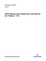
2. Select Utilities > License Key Administrator > Transfer Between
Device and Key from the ROCLINK 800 menu bar. The Transfer
Licenses Between a Device and a Key screen displays.
Figure 2-1. Transfer Licenses Between a Device and a Key

Gas Chromatograph Software Interface User Manual (for FB107)
10 Installation Revised June-2017
Note: This screen has three sections. The upper portion (Licenses
on Device) shows any software licenses installed on the
FB107. The middle portion (Licenses on Key) shows
software licenses on the license key. The lower portion of the
screen (License Key Event Log) provides a rolling log of the
last eight events related to this license key.
3. Select the key-based license you want to transfer to the FB107
(GC Interface, as shown in Figure 2-1).
4. Click Move to Device. ROCLINK moves the license from the key
to the FB107 and updates the screen.
Figure 2-2. License Installed
Note: An FB107 can hold up to six different licenses, although you
can install only one instance of each license on the FB107.
When you click Move to Device, ROCLINK 800 moves
only one instance of the license onto the FB107 and
automatically decreases the license quantity on the KEY.
5. Verify the license name displays in the Licenses on Device section
of the screen. Proceed to Section 2.2 to download the user program.
2.2 Downloading the Program
This section provides instructions for installing the program into the
Flash memory on the FB107.
Note: Connect a PC to the FloBoss’s LOI port before starting the
download.

Gas Chromatograph Software Interface User Manual (for FB107)
Revised June-2017 Installation 11
Note: Two versions of the program are included. Installation and
operation are identical between the two programs, but they use
different point type locations, different display numbers, and are
loaded into different program slots on the FB107.
GCInterface_1.bin loads into user program location 1 and uses
point types 22 and 23. GCInterface_2.bin loads into user
program location 2 and uses point types 25 and 26.
The manual shows installation of GCInterface_1.bin. Load
GCInterface_1.bin unless another user program is currently
installed in user program location 1.
To download the user program using ROCLINK 800 software:
1. Start and logon to the ROCLINK 800.
2. Select ROC > Direct Connect to connect to the ROC800.
3. Select Utilities > User Program Administrator from the
ROCLINK menu bar. The User Program Administrator screen
displays (see Figure 2-3):
Figure 2-3. User Program Administrator
4. Click Browse in the Download User Program File frame. The Select
User Program File screen displays (see Figure 2-4).
5. Select the path and user program file to download from the CD-
ROM (Program files are typically located in the Program Files

Gas Chromatograph Software Interface User Manual (for FB107)
12 Installation Revised June-2017
folder on the CD-ROM). As Figure 2-4 shows, the screen lists all
valid user program files with the .BIN extension:
Note: Load only one of the included program files. The manual
shows installation of GCInterface_1.bin. Load
GCInterface_1.bin unless another user program is currently
installed in user program location 1.
Figure 2-4. Select User Program File
6. Click Open to select the program file. The User Program
Administrator screen displays. As shown in Figure 2-5, note that the
Download User Program File frame identifies the selected program
and that the Download & Start button is active:

Gas Chromatograph Software Interface User Manual (for FB107)
Revised June-2017 Installation 13
Figure 2-5. User Program Administrator
7. Click Download & Start to begin loading the selected program.
The following message displays:
Figure 2-6. Confirm Download
8. Click Yes to begin the download. When the download completes the
following message displays:
Figure 2-7. ROCLINK 800 Download Confirmation

Gas Chromatograph Software Interface User Manual (for FB107)
14 Installation Revised June-2017
9. Click OK. The User Program Administrator screen displays (see
Figure 2-8). Note that:
The User Programs Installed in Device frame identifies the
installed program(s).
The Status field indicates that the program is running.
Figure 2-8. User Program Administrator
Note: If you install the program before you install the license key,
the Status field reads “License Key Not Found.”
10. Click Close. Proceed to Chapter 3 – Configuration to configure the
program.

Gas Chromatograph Software Interface User Manual (for FB107)
Revised June-2017 Configuration 15
Chapter 3 – Configuration
This section provides information on how to configure the Gas
Chromatograph user program.
After you have loaded the GC Interface program on the FB107, you
configure the program using three program-specific screens (GC
Interface, GC Configuration, and GC Stream Data) and one ROCLINK
800 screen (Meter Setup):
Use the GC Interface screen to configure one or more GC addresses,
select a Comm port, modify the Modbus Register Table location (if
necessary), assign the GC streams to meter runs, enable GC polling,
and enable auto-configuration.
Use the GC Configuration screen to set GC-specific parameters,
including component IDs, GC alarm options, hexane plus options,
data limits, and heating value adjustment parameters.
Use the GC Stream Data screen to verify communications between
the GC and the FB107, set SRBX alarms, and configure stream-
specific heating value checks.
Use the Fluid Properties tab on the ROCLINK 800 Meter Setup
screen to indicate the type of heating value read from the GC and to
select the “live” gas quality option.
You must configure the software before you can establish
communications with the GC. To configure the program (after logging
onto ROCLINK 800 and successfully installing the program and license
key), proceed through the program screens as shown in this section.
Note: Using MON 2000 software, you set the Daniel GC
communications port to the SIM 2251 protocol. For all other
parameter configurations, refer to the MON 2000
documentation.
You can access all the program-specific screens from the main
ROCLINK 800 screen:

Gas Chromatograph Software Interface User Manual (for FB107)
16 Configuration Revised June-2017
Figure 3-1. Main ROCLINK 800 screen
3.1 GC Interface Screen
Use this screen to configure one or more GC addresses, select a Comm
port, modify the Modbus Register Table location (if necessary), assign
the GC streams to meter runs, enable GC polling, and enable automatic
configuration of the Modbus parameters and communications ports. To
access this screen:
1. From the Directory Tree, select User Program > GC Interface.
2. Double-click Display #22 GC Interface. The GC Interface screen
displays:
/