Dell FN IO Module Owner's manual

Category
Network switches
Type
Owner's manual

This manual is also suitable for

A Dell EMC Deployment and Configuration Guide
PowerEdge FX2 FN I/O Module VLT
Deployment Guide
Configuring, testing and validating VLT on a pair of FN410S I/O Modules in a
PowerEdge FX2 chassis (v2.2)
A Dell Deployment Guide
Dell Networking Solutions Engineering
August 2016
2 PowerEdge FX2 FN I/O Module VLT Deployment Guide | Version 2.2
Revisions
Date
Description
Authors
August 2016
V2.2 DNOS updates
DNSE: EB, SJC
July 2016
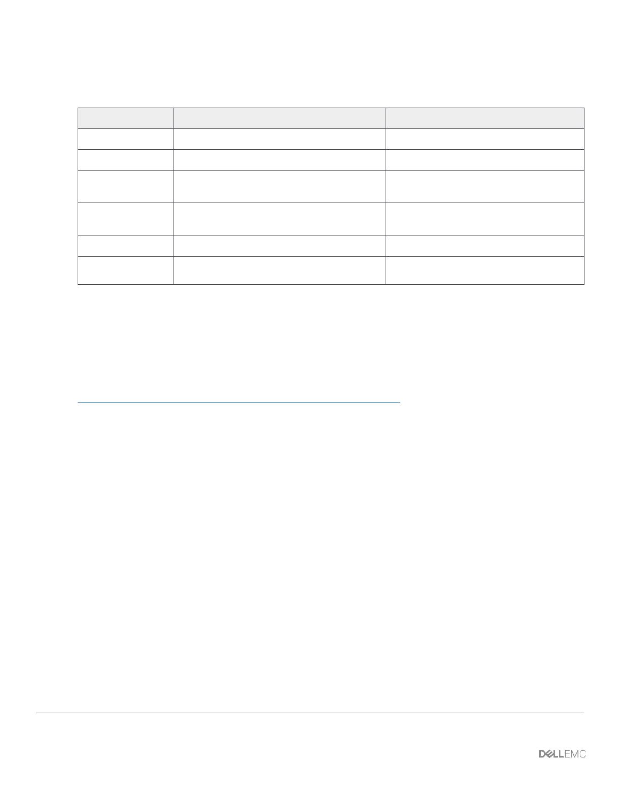
V2.1 EMC Integration changes
DNSE: EB
September 2015
V2.0 Added DNOS version 9.9 configuration
information. Added FN IOM modes section
DNSE: NB, KL, MMF, KL
July 2015
V1.2 Added additional SMUX configuration.
Removed redundant sections.
DNSE: CB, KL, MMF, JCS
May 2015
v1.1 Fixed Paragraph
DNSE: KL
December 2014
Initial Document Release
DNSE: CB, KL MMF, LC
Copyright © 2014-2016 Dell Inc. or its subsidiaries. All Rights Reserved.
Except as stated below, no part of this document may be reproduced, distributed or transmitted in any form or by any means, without express
permission of Dell.
You may distribute this document within your company or organization only, without alteration of its contents.
THIS DOCUMENT IS PROVIDED “AS-IS”, AND WITHOUT ANY WARRANTY, EXPRESS OR IMPLIED. IMPLIED WARRANTIES OF
MERCHANTABILITY AND FITNESS FOR A PARTICULAR PURPOSE ARE SPECIFICALLY DISCLAIMED. PRODUCT WARRANTIES
APPLICABLE TO THE DELL PRODUCTS DESCRIBED IN THIS DOCUMENT MAY BE FOUND AT:
http://www.dell.com/learn/us/en/vn/terms-of-sale-commercial-and-public-sector-warranties
Performance of network reference architectures discussed in this document may vary with differing deployment conditions, network loads,
and the like. Third party products may be included in reference architectures for the convenience of the reader. Inclusion of such third party
products does not necessarily constitute Dell’s recommendation of those products. Please consult your Dell representative for additional
information.
Trademarks used in this text: Dell™, the Dell logo, Dell Boomi™, PowerEdge™, PowerVault™, PowerConnect™, OpenManage™,
EqualLogic™, Compellent™, KACE™, FlexAddress™, Force10™ and Vostro™ are trademarks of Dell Inc. EMC VNX®, and EMC
Unisphere® are registered trademarks of Dell. Other Dell trademarks may be used in this document. Cisco Nexus®, Cisco MDS®, Cisco NX-
0S®, and other Cisco Catalyst® are registered trademarks of Cisco System Inc. Intel®, Pentium®, Xeon®, Core® and Celeron® are
registered trademarks of Intel Corporation in the U.S. and other countries. AMD® is a registered trademark and AMD Opteron™, AMD
Phenom™ and AMD Sempron™ are trademarks of Advanced Micro Devices, Inc. Microsoft®, Windows®, Windows Server®, Internet
Explorer®, MS-DOS®, Windows Vista® and Active Directory® are either trademarks or registered trademarks of Microsoft Corporation in the
United States and/or other countries. Red Hat® and Red Hat® Enterprise Linux® are registered trademarks of Red Hat, Inc. in the United
States and/or other countries. Novell® and SUSE® are registered trademarks of Novell Inc. in the United States and other countries.
Oracle® is a registered trademark of Oracle Corporation and/or its affiliates. VMware®, Virtual SMP®, vMotion®, vCenter® and vSphere®
are registered trademarks or trademarks of VMware, Inc. in the United States or other countries. IBM® is a registered trademark of
International Business Machines Corporation. Broadcom® and NetXtreme® are registered trademarks of QLogic is a registered trademark of
QLogic Corporation. Other trademarks and trade names may be used in this document to refer to either the entities claiming the marks
and/or names or their products and are the property of their respective owners. Dell disclaims proprietary interest in the marks and names of
others.
3 PowerEdge FX2 FN I/O Module VLT Deployment Guide | Version 2.2
Table of contents
Revisions............................................................................................................................................................................. 2
1 Introduction ................................................................................................................................................................... 5
2 The Dell FX2 and FN I/O Modules ............................................................................................................................... 7
2.1 FN I/O Modules description ................................................................................................................................ 9
2.2 Networking Block FN Series Operational Modes ............................................................................................... 9
3 Initial out-of-box connectivity check and default settings ........................................................................................... 11
4 VLT and the example environments .......................................................................................................................... 12
4.1 Benefits of VLT ................................................................................................................................................. 13
4.2 Typographical conventions and common abbreviations .................................................................................. 15
5 FN IOM Dell Blade I/O manager and internal port mapping features ........................................................................ 15
5.1 FN IOM Dell Blade I/O manager GUI ............................................................................................................... 15
5.2 FN IOM internal port mapping -- detailed overview .......................................................................................... 18
6 Environment One: Basic VLT deployment with VLT mode ........................................................................................ 22
6.1 Environment One: VLT mode configuration ..................................................................................................... 23
6.2 Testing VLT functionality .................................................................................................................................. 29
7 Environment Two: Dell Networking switches with mVLT and IOM in Full Switch mode ............................................ 32
7.1 Environment Two: IOM Full Switch mode configuration .................................................................................. 33
7.1.1 Configuring the IOM for Full Switch mode ........................................................................................................ 34
7.1.2 Configuring the VLTi peer link .......................................................................................................................... 35
7.2 Environment Two: Configuring the Dell Networking S4810 ............................................................................. 39
7.3 Verifying VLT Connectivity ............................................................................................................................... 42
8 Environment Three: Dell Networking switches with mVLT and FN IOM in programmable MUX mode. ................... 51
8.1 Environment Three: FN IOM configuration ....................................................................................................... 52
8.1.1 Configuring the FN IOM for programmable MUX mode ................................................................................... 53
8.1.2 Configuring VLT on the FN IOM ....................................................................................................................... 54
8.2 Environment Three: Configuring the Dell Networking S4810 ........................................................................... 58
8.3 Environment Three: Verifying VLT Connectivity ............................................................................................... 61
9 Environment Four: VLT interoperability with Cisco vPC ............................................................................................ 70
9.1 Environment Four: FN IOM configuration ......................................................................................................... 71
9.1.1 Configuring the FN IOM for programmable MUX mode ................................................................................... 71
9.1.2 Configuring VLT on the FN IOM ....................................................................................................................... 72
4 PowerEdge FX2 FN I/O Module VLT Deployment Guide | Version 2.2
9.2 Environment Four: Cisco Nexus 5000 Series vPC configuration ..................................................................... 76
9.3 Environment Four: Verify VLT connectivity ...................................................................................................... 83
9.4 Environment Four: Verify VPC connectivity ..................................................................................................... 84
A References ................................................................................................................................................................. 90
B Components ............................................................................................................................................................... 90
C Terminology ................................................................................................................................................................ 91
D Reset FN IOM to Default Factory Configuration ........................................................................................................ 94
E FN IOM initial out-of-box configuration and default settings .................................................................................... 100
E.1 Configure interfaces and the port channel on the upstream switch ............................................................... 101
E.2 Verify the configuration ................................................................................................................................... 104
F Support and feedback .............................................................................................................................................. 106
5 PowerEdge FX2 FN I/O Module VLT Deployment Guide | Version 2.2
1 Introduction
Dell Networking provides customers with the most efficient use of current networking equipment at the
lowest cost, while still providing today’s great new technologies focused around the explosive data
growth in the industry. The various application demands have driven the need for increased
bandwidth, lower latency infrastructures in today’s networks. Dell EMC’s portfolio covers all these key
areas to provide the best in service and customer experience.
Today’s businesses find it difficult to keep pace with the changing networking and enterprise
landscape. With limited resources, they must support a variety of devices that provide key business
functions, deliver IT services that are reliable and flexible, and provide discernible cost savings.
Remote
Data Centers
Dell
Servers
Dell
Storage
Data Center
Dell Network
Controllers
and Security
Campus
Remote/Branch
Office
VRTX
Dell Campus
Networking
Internet
Dell Data Center
Networking
Public Cloud
Storage
Network
WAN
Networking architecture overview
The Dell PowerEdge FX architecture is a revolutionary approach to shared infrastructure for Enterprise
Computing. It combines the density and innovative agility of hyper-scale computing with the ease of
use and efficiency of advanced management technologies. The FX2 provides a straightforward,
modular approach to infrastructure, and introduces a more practical way to manage the complex IT
needs of businesses.
6 PowerEdge FX2 FN I/O Module VLT Deployment Guide | Version 2.2
Remo te
Da ta Center s
De ll Se rvers
De ll St o rage
Data Center
De ll Net w ork
Con trollers
and S ecur ity
Ca mp us
Remote/Br anch
Offi ce
VRTX
Del l Campus Netwo rking
Intern et
D el l Data Center Ne twork ing
Pu bli c Cl oud
Storag e
Netw or
k
WA N
Dell
Servers
Dell Storage
Data Center
Dell Network
Controllers and
Security
Storage
Network
Dell Data Center
Networking
Zooming in to focus on the data center and storage networking
This deployment guide will provide a step-by-step configuration in the data center utilizing the FN I/O
Module, the PowerEdge FN410S. In this deployment guide, the two FN410S’s installed in the rear of
the FX2 chassis are configured as a virtual link trunk (VLT) pair of switches. This provides the
functionality for the pair of switches to perform as one logical switch
What is VLT?
VLT allows physical links between two switching devices to appear as a single virtual link to other
networking devices. VLT reduces the role of spanning tree protocols (STPs) by allowing link
aggregation group (LAG) terminations on two separate distribution or core switches, and by supporting
a loop-free topology. VLT provides Layer 2 multipathing, creating redundancy through increased
bandwidth, enabling multiple parallel paths between nodes and load-balancing traffic where alternative
paths exist.
7 PowerEdge FX2 FN I/O Module VLT Deployment Guide | Version 2.2
2 The Dell FX2 and FN I/O Modules
Introducing the Dell FX Architecture, a great way to bring optimized workloads, maximize efficiency
and simplify complexity in today’s data center.
Dell PowerEdge FX2
The Dell FX2 enclosure is unique in its modular capabilities that come in a compact 2U size. This
innovative design combines the density and efficiency of blade servers with the simplicity and cost
benefits of the smaller rack-based server systems.
FX2 chassis with FN IOM (FN410S)
8 PowerEdge FX2 FN I/O Module VLT Deployment Guide | Version 2.2
FX2 compute and networking modules
FX2 module descriptions
9 PowerEdge FX2 FN I/O Module VLT Deployment Guide | Version 2.2
2.1 FN I/O Modules description
The PowerEdge FX2 is a chassis capable of housing compute, network and storage modules. The
network modules, referred to as one of three FN I/O Modules (FN IOMs), behave as traditional
network switches that are housed in the rear of the FX2 chassis. All three FN IOMs offer network
services for both the Ethernet and storage fabrics in a data center. While the FN410S is used in this
deployment guide, Dell EMC offers three options of FN IOMs providing plug-and-play Ethernet as well
as LAN/SAN convergence with iSCSI and FCoE. In addition to these features, the third model also
offers native Fibre Channel traffic using NPIV Proxy Gateway mode (NPG mode).
8 x 10GbE KR Internal Facing
4 x 10GbE SFP+ External Facing
USB Console
USB Storage
FN410S
4-port SFP+ I/O Module
Provides 4 ports of SFP+ 10GbE
connectivity. Supports optical and
DAC cable media.
8 x 10GbE KR Internal Facing
4 x 10GBASE-T External Facing
USB Console
USB Storage
FN410T
4-port 10GBASE-T I/O Module
Provides 4 ports of 10GBASE-T
connectivity. Supports cost
effective copper media up to 100
meters.
8 x 10GbE KR Internal Facing
2 x 2-,4-,8-Gbit/s FC SFP+
2 x 10GbE SFP+
USB Console
USB Storage
FN2210S
4-port Combo FC/Ethernet I/O
Module
Delivers up to 2 ports of 2, 4, or
8Gbit/s Fiber Channel in NPG
mode. Ethernet is provided by 2
ports of SFP+ 10GbE connectivity.
Supports optical and DAC cable
media.
2.2 Networking Block FN Series Operational Modes
The FN IOM supports five operational modes: Standalone (SMUX), VLT, Stacking, Programmable
MUX (PMUX) and Full-switch. See Table 1 for detailed descriptions of each mode. To enable a new
operational mode the command stack-unit 0 iom-mode <IOM_Mode> is issued in configuration
mode. After enabling a new operational mode, the switch must be reloaded.
10 PowerEdge FX2 FN I/O Module VLT Deployment Guide | Version 2.2
Standalone Mode
(Default mode)
Stacking
Mode
VLT Mode
PMUX
Mode
Automated mode
No Customization
I/O Aggregation
I/O Aggregation
Offers Active-Active
multi-path for servers
Semi-customization
Full-switch
Mode
I/O Aggregation
Creates a stack up to 6
units
Semi-customization
I/O Aggregation
Offers custom
configurations using CLI
Moderate customization
L2/L3 switching
Everything needs to be
configured using CLI
Full customizations
FN410S
FN410T
FN2210S
FN Series operational modes
IOM modes and descriptions
Description
This is the factory default mode for the IOM. SMUX is a fully
automated, zero-touch mode that allows VLAN memberships to be
defined on the server-facing ports while all upstream ports are
configured in port channel 128 and cannot be modified.
In this low-touch mode, all configurations except VLAN membership
are automated. Port 9 is dedicated to the VLT interconnect in this
mode.
PMUX mode provides operational flexibility by allowing the
administrator to create multiple LAGs, configure VLANs on uplinks
and to configure DCB parameters on the server-facing ports.
In Stacking mode, multiple switches can be combined to make a
single logical switch, which is managed by a designated master unit in
the stack. This mode can be useful because it simplifies management
and redundant configurations.
In Full Switch mode, all switch features are made available. This mode
requires the most configuration, but allows for the most flexibility and
customization.
11 PowerEdge FX2 FN I/O Module VLT Deployment Guide | Version 2.2
3 Initial out-of-box connectivity check and default settings
The environments documented within this guide cover configuring Virtual Link Trunking (VLT) in
various topologies; however, many times there will be a need to simply bring up a single networking
connection in the data center without VLT. This will be connecting a single link from the FN IOM to the
ToR switch without configuration on the FN IOM side to show that basic network connections work.
Out of the box, the FN IOM will come in Standalone mode with the applicable default settings this
mode has in place. This applies to FN 410S, FN 410T, and FN 2210S (applicable to ports in Ethernet
mode only).
Three easy steps cover this process:
1. Ensure the FN IOM is in Standalone Mode
2. Create an LACP LAG on the upstream top-of-rack (ToR) switch
3. Verify the connection
More detail on these steps can be found in Appendix E.
Note: Default settings on the FN IOM will have the server facing network ports shut down until the
uplink port channel is operational to the ToR (top of rack) switch. This is due to a feature called
Uplink Failure Detection whereby, when upstream connectivity fails, the FN IOM disables the
downstream links. This feature is essential for fail-over between two ports on the same CNA/NIC
adapter.
For more information on Uplink Failure Detection and all other configuration settings, see the Dell
PowerEdge FN I/O Module Configuration Guide.
12 PowerEdge FX2 FN I/O Module VLT Deployment Guide | Version 2.2
4 VLT and the example environments
The rest of this guide illustrates configuring two FN410S FN I/O Modules in a PowerEdge FX2 chassis
to use the VLT protocol for redundant, load-balanced connections. The initial configuration from the
default Standalone mode to VLT, Full Switch and Programmable Mux mode can be performed either
via the Dell Blade I/O Manager GUI or via standard CLI. This configuration works with the FN410S,
FN410T and FN2210S (applicable to ports in Ethernet mode only).
This document describes four VLT environments in a step-by-step manner:
Environment 1 - a basic VLT deployment using low-touch mode is presented.
Environment 2 - an example of multi-Virtual Link Trunking (mVLT) using Full Switch mode
configuration.
Environment 3 - an example of mVLT using Programmable MUX (PMUX) mode configuration.
Environment 4 - the FN IOMs are incorporated into a Cisco Nexus environment utilizing virtual
Port Channel (vPC) to create a fully redundant layer 2 topology.
Note: In order to utilize the new Dell Blade I/O Manager GUI, as well as the new Full Switch mode
feature, the FN IOM Switching modules will need to be upgraded to Dell Networking Operating
System (DNOS) 9.10 firmware. Please refer to the DNOS release notes included with the 9.10
firmware for the FN IOM upgrade procedure.
13 PowerEdge FX2 FN I/O Module VLT Deployment Guide | Version 2.2
4.1 Benefits of VLT
In a non-Virtual Link Trunking (VLT) environment utilizing spanning tree protocol, as in Figure 8,
redundancy involves idle equipment and increased costs with no added value in the event of a device
failure. On the other hand, in a VLT environment (Figure 9), all paths are active, utilizing all available
links and switches to their fullest potential. This doubles the throughput, thus increasing performance
and adding immediate value.
Non-VLT
Environment
Active Path
Idle
Non-VLT Environment with Active/Passive (Standby)
VLT
Environment
Active Path
VLT Active-Active Environment
VLT also takes advantage of teamed Network Interface Cards (NICs) and switch pairs, causing them
to appear as a single switch to devices outside the VLT domain. The physical versus logical
connectivity, using a pair of FN IOMs in a PowerEdge FX2 chassis, is illustrated below in Figure 10
and Figure 11.
14 PowerEdge FX2 FN I/O Module VLT Deployment Guide | Version 2.2
NIC Port 1
NIC Port 2
TEAM
Internal
Connections
Te0/1
Te0/1
Blade Server 1
FN410S-A1
FN410S-A2
PowerEdge FX2
Chassis
Internal interfaces
participating in VLT
VLT member/
interfaces
VLTi / ICL peer link
Physical Connectivity in a PowerEdge FX2 Chassis Using IOMs
NIC1
NIC2
TEAM Virtual
Interface
PowerEdge FX2
Chassis
Logical view of Teamed Virtual
Interface connected to two IOMs as
one logical switch
Logical Connectivity in a PowerEdge FX2 Chassis Using IOMs
15 PowerEdge FX2 FN I/O Module VLT Deployment Guide | Version 2.2
4.2 Typographical conventions and common abbreviations
The following conventions are used in the command line examples in this document:
Monospace
Text
CLI (Command Line Interface) examples
Italic
Monospace
Text
Variables in CLI examples
Bold
monospace
Text
Commands entered at the CLI prompt
5 FN IOM Dell Blade I/O manager and internal port
mapping features
5.1 FN IOM Dell Blade I/O manager GUI
In previous versions of the Dell Networking Operation System (DNOS) 9.x, the FN410S, FN410T and
FN2210S FX2 switching modules were only configurable via CLI. Now, with DNOS 9.10 these FX2
switching modules can be configured for most common deployments with an easy to use GUI
application. The new “Dell Blade I/O Manager” GUI application allows IT administrators to configure
features such as:
Configuring modes, combo ports, account credentials, SNMP parameters, uplink failure
detection and NTP through the Initial Setup Wizard
Viewing logs and alerts and configuring settings for viewing logs and alerts
Viewing port settings and configuring port settings, uplink ports, uplink failure detection, and
combo port settings
Assigning VLANs, Configuring LAGs, IGMP, Port Mirroring, Fibre Channel, iSCSI, and DCB
Configuring TACACS+, RADIUS, AAA
Configuring FN IOM users and passwords
Configuring Broadcast Storm Control
Configuring Auto LAG
Configuring the default VLAN
Configuring NTP servers
Rebooting the FN IOM
The features listed above allow IT administrators to quickly deploy the FX2 FN IOMs in most data
center environments. The Dell Blade I/O Manager is typically launched from the FX2 CMC > I/O
16 PowerEdge FX2 FN I/O Module VLT Deployment Guide | Version 2.2
Module Overview section, but it can also be launched by typing the management IP address of the
FN IOM into a browser with a port number of 8081, i.e. 172.25.189.209:8081
The FX2 CMC I/O Module Overview page (Figure 12) is the preferred method to launch the FN IOM
Dell Blade I/O Manager GUI. When the Launch I/O Module GUI button is clicked the login page
(Figure 13) will allow authorized users access to this feature-rich application.
FX2 CMC I/O module overview
17 PowerEdge FX2 FN I/O Module VLT Deployment Guide | Version 2.2
FX2 FN IOM Dell Blade IO manager login screen
When the correct account credentials (default is root/calvin) are entered into the Dell Blade I/O
Manager Login page, the initial Dashboard view will be presented (Figure 14).
Dell Blade I/O manager dashboard
18 PowerEdge FX2 FN I/O Module VLT Deployment Guide | Version 2.2
The Dell Blade I/O Manager Dashboard page allows an overall configuration view of the FN IOM,
which includes:
FN IOM Mode
Management IP address
Recently logged activity
Bandwidth utilization
Detailed Port view
Detailed mode view (Standalone, VLT, Stacked, Programmable Mux, Full Switch)
The menu choices on the left include logging information, Port configuration (both internal and
external), Switching, Security, and Settings. As can be seen from this brief overview, the FN IOM Dell
Blade I/O Manager can provide much of the functionality that is typically relegated to the CLI.
5.2 FN IOM internal port mapping -- detailed overview
Quarter-height slots - dual-port CNAs
In quarter-height slots configured with dual-port CNAs, the servers map to a single port on each of the
two IOAs.
The naming convention for quarter-height slots are different from the naming conventions for the half-
height and full-height slots. As shown in Figure 1514, the first row of the quarter-height slots are
designated 1a through 1d, and the second row 3a through 3d. Figure 15 and Table 2 present the port
mapping for quarter-height slots with dual-port CNAs.
Note: Quad-port CNAs are not available for quarter-height servers.
19 PowerEdge FX2 FN I/O Module VLT Deployment Guide | Version 2.2
FN2210S IOA A1 (Top)
Internal Ports
5 6
3
7
4
8
2
FN2210S IOA A2 (Bottom)
Internal Ports
1b
3a 3b
1c 1d
3c 3d
5 6
3
7
4
8
21
1
1a
Quarter-height slots with dual-port CNAs
Half-height slots with dual-port CNAs
Slot
IOA A1 port
numbers
(top)
IOA A2 port
numbers
(bottom)
1a
1
1
1b
2
2
1c
3
3
1d
4
4
3a
5
5
3b
6
6
3c
7
7
3d
8
8
20 PowerEdge FX2 FN I/O Module VLT Deployment Guide | Version 2.2
Half-height slots dual-port CNAs
In half-height slots with dual-port CNAs installed in the server blades, the servers map to a single port
on each of the two IOAs. Figure 16 and Table 3 present the port mapping for half-height slots with
dual-port CNAs.
Note: Ports 2, 4, 6 and 8 are not used when using half-height blades with dual-port adapters.
Slot 2
Slot 3 Slot 4
FN2210S IOA A1 (Top)
Internal Ports
5 6
3
7
4
8
21
FN2210S IOA A2 (Bottom)
Internal Ports
5 6
3
7
4
8
1
Slot 1
2
IOA Port mapping half-height slots with dual-port CNAs
Half-height slots with dual-port CNAs
Slot
IOA A1
port
numbers
(top)
IOA A2 port
numbers
(bottom)
1
1
1
2
3
3
3
5
5
4
7
7
  • Page 1 1
  • Page 2 2
  • Page 3 3
  • Page 4 4
  • Page 5 5
  • Page 6 6
  • Page 7 7
  • Page 8 8
  • Page 9 9
  • Page 10 10
  • Page 11 11
  • Page 12 12
  • Page 13 13
  • Page 14 14
  • Page 15 15
  • Page 16 16
  • Page 17 17
  • Page 18 18
  • Page 19 19
  • Page 20 20
  • Page 21 21
  • Page 22 22
  • Page 23 23
  • Page 24 24
  • Page 25 25
  • Page 26 26
  • Page 27 27
  • Page 28 28
  • Page 29 29
  • Page 30 30
  • Page 31 31
  • Page 32 32
  • Page 33 33
  • Page 34 34
  • Page 35 35
  • Page 36 36
  • Page 37 37
  • Page 38 38
  • Page 39 39
  • Page 40 40
  • Page 41 41
  • Page 42 42
  • Page 43 43
  • Page 44 44
  • Page 45 45
  • Page 46 46
  • Page 47 47
  • Page 48 48
  • Page 49 49
  • Page 50 50
  • Page 51 51
  • Page 52 52
  • Page 53 53
  • Page 54 54
  • Page 55 55
  • Page 56 56
  • Page 57 57
  • Page 58 58
  • Page 59 59
  • Page 60 60
  • Page 61 61
  • Page 62 62
  • Page 63 63
  • Page 64 64
  • Page 65 65
  • Page 66 66
  • Page 67 67
  • Page 68 68
  • Page 69 69
  • Page 70 70
  • Page 71 71
  • Page 72 72
  • Page 73 73
  • Page 74 74
  • Page 75 75
  • Page 76 76
  • Page 77 77
  • Page 78 78
  • Page 79 79
  • Page 80 80
  • Page 81 81
  • Page 82 82
  • Page 83 83
  • Page 84 84
  • Page 85 85
  • Page 86 86
  • Page 87 87
  • Page 88 88
  • Page 89 89
  • Page 90 90
  • Page 91 91
  • Page 92 92
  • Page 93 93
  • Page 94 94
  • Page 95 95
  • Page 96 96
  • Page 97 97
  • Page 98 98
  • Page 99 99
  • Page 100 100
  • Page 101 101
  • Page 102 102
  • Page 103 103
  • Page 104 104
  • Page 105 105
  • Page 106 106

Dell FN IO Module Owner's manual

Category
Network switches
Type
Owner's manual
This manual is also suitable for

Ask a question and I''ll find the answer in the document

Finding information in a document is now easier with AI