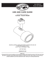
Hampton Bay EC1577WH Installation guide

Type
Installation guide

Regal King EC1577WH is a 3-light linear track lighting system, which is part of the Hampton Bay EC series. It is intended for use with Hampton Bay EC series line voltage track systems only. Some of its capabilities include:

  • Pendant mounting is not allowed, only track mounting.
  • The mounting screws are to be mounted along the track in the keyhole slots provided.
  • All electrical connections must be in accordance with local codes and the National Electrical Code.
  • Do not attempt to energize anything other than EC series track lighting fixtures or components on the track.
THANK YOU
create quality products designed to enhance your home. Visit us online to see our full line of products available for your home improvement
needs. Thank you for choosing Hampton Bay!
USE AND CARE GUIDE
Questions, problems, missing parts? Before returning to the store call
Hampton Bay Customer Service
8 a.m. - 6 p.m., EST, Monday - Friday
1-877-527-0313
HOMEDEPOT.COM
Item #539-805
Model #EC1577WH
3 Light Linear Track Kit
linear track kit. We strive to continually
2
Table of Contents
IMPORTANT SAFETY INSTRUCTIONS
Safety Information
WARNING: Do not install this lighting system in a damp or
wet location.
IMPORTANT: For use with Hampton Bay EC series line
voltage track systems only.
CAUTION: Lighted lamp is hot!
Read all instructions. Save these instructions and refer to them
made.
Do not install any part of this track system less than 7 feet
Do not install any lamps closer than 6 inches from any curtain
or similar combustible material.
This track system is not intended for use with a power supply
cord or convenience receptacle adaptor.
This track system must be supplied by a single branch
120 volt circuit.
The track is not intended to be pendant mounted such as by a
stem or cable.
The mounting screws are to be mounted along the track in the
keyhole slots provided.
Disconnect electrical power before adding to or changing the
CAUTION: To reduce the risk of a burn during re-lamping,
remove from the track before re-lamping.
CAUTION: Hot surface, keep away from curtains or
any other combustible material.
NOTE: All electrical connections must be in accordance with
local codes and the National Electrical Code. If you are
unfamiliar with methods of installing electrical wiring, secure
Table of Contents
......................................
2
Safety Information
....................................
2
Warranty
...................................................
...................................................
3
3
3
.....................................
.....................................
.....................................
Tools required
3
Hardware Included
.....................................
4
Package Contents
Pre-Installation
.........................................
Installation
Operation
Care and Cleaning
........................................
8
8
8
5
Troubleshooting
........................................
SAVE THESE INSTRUCTIONS
CAUTION: Do not touch lamp at any time. Use a soft cloth.
Oil from skin may damage lamp.
Before energizing, make sure that the lighting system is clear
of all material which could cause a direct short, and check all
electrical connections to make sure they are secure.
Do not attempt to energize anything other than EC series track
tools, extension cords, appliances, etc. to the track.
Lamp gets hot quickly! Touch only the switch or plug when
turning on. Do not touch the hot lamp lens. Turn off power and
allow bulbs to cool down before replacing.
WHEN INSTALLING OR USING THIS TRACK SYSTEM, BASIC SAFETY PRECAUTIONS SHOULD ALWAYS BE FOLLOWED INCLUDING THE
FOLLOWING:
lighting xtures or components on the track. To reduce the risk
of re and electrical shock, do not attempt to connect power
3
Warranty
PLANNING INSTALLATION
TOOLS REQUIRED
Ladder Safety
goggles
Wire
stripper
Gloves
Phillips
screwdriver
Electrical
tape
Drill 7/32 in. or 5/8 in. Drill bits
HARDWARE INCLUDED
AA
B
B
CC
DD
EE
Pre-installation
Part
Description
Quantity
2stlbo elggoT AA
2
wercs spillihP
BB
2
rohcnA
CC
DD
Wire connector
3
2wercs enihcaM EE
Contact the Customer Service Team at 1-877-527-0313 or visit www.homedepot.com.
Read all instructions before assembly.
To avoid damaging this product, assemble it on a soft, non-abrasive surface such as carpet or cardboard. Inspect each part for
damage that may have occurred during shipping.
Keep your receipt and these instructions for proof of purchase.
Hacksaw
rs from
date of purchase. This warranty applies only to the original consumer purchaser and only to products used in normal use and service. If
this product is found to be defective, the manufacturer’s only obligation, and your exclusive remedy, is the repair or replacement of the
product at the manufacturer’s discretion, provided that the product has not been damaged through misuse, abuse, accident,
operly
installed, set-up, or used in any way not in accordance with the instructions supplied with the product. This warranty shall not apply to
a failure of the product as a result of an accident, misuse, abuse, negligence, alteration, or faulty installation, or any other failure not
urface
and/or weathering, as this is considered normal wear and tear. The manufacturer does not warrant and specially disclaims any warranty,
disclaims any liability and shall not be liable for any consequential or incidental loss or damage, including but not limited to any labor/
expense costs involved in the replacement or repair of said product.
NOTE: Hardware not shown to actual size.
HOMEDEPOT.COM
Please contact 1-877-527-0313 for further assistance.
4
Pre-installation (continued)
PACKAGE CONTENTS
Description
Quantity
A
2
B
1
C
1
D
1
E
2
F
1
G
3
3
3
3
H
Bulb
J
I
B
A
C
D
E
F
G
H
I
J
Part
Track mounting screw [preassembled to mounting plate (B)]
Mounting plate
Twist-lock connector [preassembled to mounting plate (B)]
Canopy [preassembled to mounting plate (B)]
Canopy screw [preassembled to canopy (D)]
Track section
Track head
Trim [preassembled to track head (G)]
Connector’s locking tab [preassembled to track head (G)]
5
Installation
1
B
2
Loosen the track mounting screws (A) preassembled to the
mounting plate (B).
Do not remove the track mounting screws (A) completely.
E
D
B
A
Field cuttin
g the track to special
lengths (Optional)
Separating the canopy
F
NOTE: Cutting should be done preferably from the dead end of the track.
Remove all burrs, insulators, and copper bus bars from the
track.
Push the copper bus bars back into the insulators 3/8th in.
from the end of the insulators.
After you complete step 4, the bus bar insulators should be
a minimum of 3/8th in. and a maximum of ½ in. from each
end of the insulator. If this is not the case, make appropriate
Reinstall the dead end and/or appropriate feed connector,
and tighten the screw.
length of track that is 4 feet or less in length has one mounting
opening spaced a maximum of 6 in. from each track end
section. A single section of track that is greater than 4 feet
in length must have mounting openings a maximum of 12 in.
from each end of the track with additional openings a
minimum of every 4 feet along the length of the track section.
Additional openings every 4 feet along the track section may
be added as needed.
Remove the canopy screws (E) from the canopy (D) to
expose the mounting plate (B).
HOMEDEPOT.COM
Please contact 1-877-527-0313 for further assistance.
and bus bars even to end) to the desired length. Be sure to
reinstalled to the track end.
6
Installation (continued)
3
DD
Outlet Box
Installing the mounting bracket
4
EE B
Secure the mounting plate (B) to the outlet box with machine
screws (EE).
Installing the track to the ceiling
5
F
AA
Place the linear track section (F) in the desired location on the mounting plate (B) between the two track mounting screws (A).
Mark the location of the track section (F) on the ceiling with a pencil (not included) through the mounting holes in the bottom of the
track section (F).
Attach the track section (F) to the desired location on the ceiling in one of the following ways:
Drill a 5/8 in. hole at each mark on the ceiling.
Insert toggle bolts (AA) through the track section (F), and
thread 1/2 in. toggle onto bolts.
Place the track section (F) against the ceiling, and insert the
toggle bolts (AA) into the holes until the spring open.
Tighten the bolts (AA).
5a
Connecting the wires
NOTE: Toggle bolts (AA) should be used for standard installation into drywall, drop ceiling, or suspended ceiling
applications. Anchors (CC) are used for masonry installations ONLY.
Toggle bolt installation
Connect the wires (white wires from connector to the white
wires from the supply circuit, black wires from the connector
to the black wires from the supply circuit, and the green
ground wire from the connector to the ground wire of the
supply circuit) using the wire connectors (DD).
Wrap electircal tape (not included) around wire connectors
(DD) and make sure they are secure.
Push all excess wire and wire connectors (DD) back into the
outlet box (not included).
Align the holes in the mounting plate (B) with the holes in the
outlet box.
B
F
A
7
C
F
B
D
E
5b
Anchor installation
6
7
BB
F
CC
Installation (continued)
Drill a 7/32 in. hole at each mark on the ceiling, and insert
the anchors (CC) into the mounting surface.
Insert the Phillips screws (BB) through the track section (F),
and tighten to the anchors (CC).
Attaching the mounting plate to the track
Connecting the canopy to the track
Remove the trim (I) from the track head (G).
Installing the bulb
G
I
H
8
Pull the bulb socket from the track head (G) and insert the
bulb (H) into the socket.
Attach the trim (I) to the bulb (H). Reattach the trim (I) to the
track head (G).
Tighten the track mounting screws (A) to secure the track
section (F) to the mounting plate (B).
Twist the twist-lock connector (C) into the track section (F).
Secure the canopy (D) to the mounting plate (B) by tightening
the previously removed canopy screws (E).
When the twist-lock connector (C) is twisted into position on
the track section (F), make sure the two copper tabs on the
side of the twist-lock connector (C) align with the two copper
strips inside the track section (F). This is necessary to
maintain polarity.
HOMEDEPOT.COM
Please contact 1-877-527-0313 for further assistance.
G
F
G
J
F
8
Installing the track head to the track
Removing the track head from the track
Installation (continued)
9
Operation
Care and Cleaning
CAUTION:
Problem
Possible
C
ause
Solution
Make sure the power supply is on.
There is a faulty wire connection.
There is a faulty switch.
There are crossed wires, or the power
wire is not properly grounded.
NOTE: The ground side of the track head (G) connector is the side with two
metal tabs. The ground side of the track section (F) has an indented groove
on the face and two internal copper strips. The track head (G) can only be
assembled if the ground sides of the track head (G) connector and the track
section (F) are aligned.
J
The light bulb will
not illuminate.
Check the wire connections.
Identify the ground side on the track head (G) connector and track
section (F).
Push the top portion of the track head (G) connector into the slot of the
track section (F).
Pull down the connector’s locking tab (J). Twist the ground side of the track
head (G) connector toward the ground side of the track section (F) until the
track head (G) connector snaps into place.
Ground tab
Ground groove
Ground side of connector
Use a dry or slightly dampened, clean cloth (use clean water, never use a solvent) to wipe the interior and exterior surfaces of the
Troubleshooting
Fuse blows or circuit breaker trips
when the light bulb is illuminated.
The light bulb is burned out.
The power is off.
Replace the light bulb.
Check the wiring.
you are not comfortable troubleshooting
wiring problems.
Test or replace the switch.
track head (G) to cool down.
Pull down on the track head connector’s locking tab (J), and twist until
the track head (G) disengages.
Questions, problems, missing parts? Before returning to the store,
call Hampton Bay Customer Service
8 a.m. - 6 p.m., EST, Monday-Friday
1-877-527-0313
HOMEDEPOT.COM
Retain this manual for future use.
  • Page 1 1
  • Page 2 2
  • Page 3 3
  • Page 4 4
  • Page 5 5
  • Page 6 6
  • Page 7 7
  • Page 8 8
  • Page 9 9
  • Page 10 10
  • Page 11 11
  • Page 12 12
  • Page 13 13
  • Page 14 14
  • Page 15 15
  • Page 16 16
  • Page 17 17
  • Page 18 18
  • Page 19 19
  • Page 20 20
  • Page 21 21
  • Page 22 22
  • Page 23 23
  • Page 24 24
  • Page 25 25
  • Page 26 26
  • Page 27 27

Hampton Bay EC1577WH Installation guide

Type
Installation guide

Regal King EC1577WH is a 3-light linear track lighting system, which is part of the Hampton Bay EC series. It is intended for use with Hampton Bay EC series line voltage track systems only. Some of its capabilities include:

  • Pendant mounting is not allowed, only track mounting.
  • The mounting screws are to be mounted along the track in the keyhole slots provided.
  • All electrical connections must be in accordance with local codes and the National Electrical Code.
  • Do not attempt to energize anything other than EC series track lighting fixtures or components on the track.

Ask a question and I''ll find the answer in the document
Finding information in a document is now easier with AI