Page is loading ...

SITRANS F
Coriolis flowmeters
SITRANS F C MASS 2100 Di 3-40
Operating Instructions • 07/2010
SITRANS F


1
Introduction
2
Safety notes
3
Description
SITRANS F
4
Installing/Mounting
Coriolis Flowmeters
SITRANS F C MASS 2100 Di 3-40
5
Connecting
6
Commissioning
Operating Instructions
7
Service and maintenance
8
Technical data
A
Appendix
Coriolis flow sensor type MASS 2100 Di 3, 6, 15, 25
or 40 designed for use with transmitter types
SITRANS F C MASS 6000 or SIFLOW FC070
07/2010
A5E02896535-01

Legal information
Warning notice system
This manual contains notices you have to observe in order to ensure your personal safety, as well as to prevent
damage to property. The notices referring to your personal safety are highlighted in the manual by a safety alert
symbol, notices referring only to property damage have no safety alert symbol. These notices shown below are
graded according to the degree of danger.
DANGER
indicates that death or severe personal injury will result if proper precautions are not taken.
WARNING
indicates that death or severe personal injury may result if proper precautions are not taken.
CAUTION
with a safety alert symbol, indicates that minor personal injury can result if proper precautions are not taken.
CAUTION
without a safety alert symbol, indicates that property damage can result if proper precautions are not taken.
NOTICE
indicates that an unintended result or situation can occur if the corresponding information is not taken into
account.
If more than one degree of danger is present, the warning notice representing the highest degree of danger will
be used. A notice warning of injury to persons with a safety alert symbol may also include a warning relating to
property damage.
Qualified Personnel
The product/system described in this documentation may be operated only by personnel qualified for the specific
task in accordance with the relevant documentation for the specific task, in particular its warning notices and
safety instructions. Qualified personnel are those who, based on their training and experience, are capable of
identifying risks and avoiding potential hazards when working with these products/systems.
Proper use of Siemens products
Note the following:
WARNING
Siemens products may only be used for the applications described in the catalog and in the relevant technical
documentation. If products and components from other manufacturers are used, these must be recommended
or approved by Siemens. Proper transport, storage, installation, assembly, commissioning, operation and
maintenance are required to ensure that the products operate safely and without any problems. The permissible
ambient conditions must be adhered to. The information in the relevant documentation must be observed.
Trademarks
All names identified by ® are registered trademarks of the Siemens AG. The remaining trademarks in this
publication may be trademarks whose use by third parties for their own purposes could violate the rights of the
owner.
Disclaimer of Liability
We have reviewed the contents of this publication to ensure consistency with the hardware and software
described. Since variance cannot be precluded entirely, we cannot guarantee full consistency. However, the
information in this publication is reviewed regularly and any necessary corrections are included in subsequent
editions.
Siemens AG order number: A5E02896535 Copyright © Siemens AG 2010.
Industry Sector Ⓟ 08/2010 Technical data subject to change
Postfach 48 48
90026 NÜRNBERG
GERMANY

SITRANS F C MASS 2100 Di 3-40
Operating Instructions, 07/2010, SFIDK.PS.028.Z1.02
3
Table of contents
1 Introduction................................................................................................................................................ 5
1.1 Items supplied................................................................................................................................5
1.2 History............................................................................................................................................6
1.3 Further Information ........................................................................................................................6
2 Safety notes............................................................................................................................................... 9
2.1 Laws and directives .......................................................................................................................9
2.2 Installation in hazardous area......................................................................................................10
3 Description............................................................................................................................................... 13
3.1 Design..........................................................................................................................................13
3.2 Theory of operation......................................................................................................................15
4 Installing/Mounting................................................................................................................................... 17
4.1 Installation safety precautions......................................................................................................17
4.2 Determining a location .................................................................................................................18
4.3 Orienting the sensor.....................................................................................................................19
4.4 Mounting the sensor ....................................................................................................................21
4.5 Mounting a pressure guard..........................................................................................................22
5 Connecting .............................................................................................................................................. 23
5.1 Safety precautions .......................................................................................................................23
5.2 Wiring...........................................................................................................................................24
5.3 Turning the terminal box ..............................................................................................................25
6 Commissioning ........................................................................................................................................ 27
6.1 Zero point adjustment ..................................................................................................................27
7 Service and maintenance ........................................................................................................................ 29
7.1 Maintenance.................................................................................................................................29
7.2 Transportation/storage.................................................................................................................29
7.3 Recalibration ................................................................................................................................29
7.4
Unit repair.....................................................................................................................................30
7.5 Technical support.........................................................................................................................30
7.6 Return procedures .......................................................................................................................31
8 Technical data ......................................................................................................................................... 33
8.1 Technical specifications ...............................................................................................................33
8.2 Measurement range.....................................................................................................................34

Table of contents
SITRANS F C MASS 2100 Di 3-40
4 Operating Instructions, 07/2010, SFIDK.PS.028.Z1.02
8.3 Accuracy specifications............................................................................................................... 35
8.4 Pressure drop.............................................................................................................................. 36
8.5 Pressure / temperature range ..................................................................................................... 38
8.6 Electrical connection schematics................................................................................................ 41
8.7 Dimensions and weight............................................................................................................... 42
A Appendix.................................................................................................................................................. 47
A.1 Ordering ...................................................................................................................................... 47
Glossary .................................................................................................................................................. 49
Index........................................................................................................................................................ 53

SITRANS F C MASS 2100 Di 3-40
Operating Instructions, 07/2010, SFIDK.PS.028.Z1.02
5
Introduction
1
These instructions contain all the information you need for using the device.
The instructions are aimed at persons mechanically installing the device, connecting it
electronically, configuring the parameters and commissioning it as well as service and
maintenance engineers.
Note
It is the responsibility of the customer that the instructions and directions provi
ded in the
manual are read, understood and followed by the relevant personnel before installing the
device.
1.1 Items supplied
• MASS 2100 sensor
• Sensorprom
• Calibration report
• Quick Start
• SITRANS F technical literature CD-ROM
Inspection
1. Check for visual mechanical damage due to possible improper handling during shipment.
All claims for damage are to be made promptly to the carrier.
2. Make sure the scope of delivery, and the information on the type plate corresponds to
your order and the delivery note.

Introduction
1.2 History
SITRANS F C MASS 2100 Di 3-40
6 Operating Instructions, 07/2010, SFIDK.PS.028.Z1.02
Identification
&RGH1R
;;;;;;;;;;;;;;;;;;;;;;;;;;;;;;;;;;;;;;;;;;
6HULDO1R
'131
37<HDU
&RQQHFWLRQ
0DWHULDO
&DO)DFWRU
7PHGLDrWRr&,3,3
;;;;;;;;;;;;;;;;
0(;;;;;;;;;1::<
;;;;;;;;;;;;
;;EDU;;
;;;;;;;;;;
;;;;;O
;;;;;;;;;;;
(1FDWHJRU\,,
,,*
'(0.2$7(;;
([LD,,&77
6HQVRUW,QWULQVLFVDIHW\VSHFLILFDWLRQ
6((0$18$/55
7(&+1,&$/'$7$,17(5)$&('$7$
6LHPHQV$6)ORZ,QWUXPHQWV
0DGHLQ'HQPDUN1RUGERUJYHM1RUGERUJ
6,75$16)&0$66
① Code number Device specific code number
② Serial number Device specific serial number
③ DN / PN Process connector nominal size / sensor pressure rating
④ PT / Year Test pressure and time stamp
⑤ Connection Process connector
⑥ Material Material of the pipe
⑦ Cal. factor Device specific calibration factor
Figure 1-1 MASS 2100 Type plate
1.2 History
The contents of these instructions are regularly reviewed and corrections are included in
subsequent editions. We welcome all suggestions for improvement.
The following table shows the most important changes in the documentation compared to
each previous edition.
Edition Remarks
07/2010 First edition of Operating Instructions for SITRANS F C MASS 2100 DN 3-40.
The document replaces all previous Instructions for use.
1.3 Further Information
The contents of these Operating Instructions shall not become part of or modify any prior or
existing agreement, commitment or legal relationship. All obligations on the part of Siemens
AG are contained in the respective sales contract which also contains the complete and
solely applicable warranty conditions. Any statements contained herein do not create new
warranties or modify the existing warranty.

Introduction
1.3 Further Information
SITRANS F C MASS 2100 Di 3-40
Operating Instructions, 07/2010, SFIDK.PS.028.Z1.02
7
Product information on the Internet
The Operating Instructions are available on the CD-ROM shipped with the device, and on
the Internet on the Siemens homepage, where further information on the range of SITRANS
F flowmeters may also be found:
Product information on the internet (http://www.siemens.com/flowdocumentation
)
Worldwide contact person
If you need more information or have particular problems not covered sufficiently by the
operating instructions, please get in touch with your contact person. You can find contact
information for your local contact person on the Internet:
Local contact person (http://www.automation.siemens.com/partner
)
See also
Technical support (Page 30)

Introduction
1.3 Further Information
SITRANS F C MASS 2100 Di 3-40
8 Operating Instructions, 07/2010, SFIDK.PS.028.Z1.02

SITRANS F C MASS 2100 Di 3-40
Operating Instructions, 07/2010, SFIDK.PS.028.Z1.02
9
2
Safety notes
CAUTION
Correct, reliable operation of the product requires proper transport, storage, positioning and
assembly as well as careful operation and maintenance. Only qualified personnel should
install or operate this instrument.
Note
Alterations to the product, including opening or improper repairs
of the product, are not
permitted.
If this requirement is not observed, the CE mark and the manufacturer's warranty will expire.
2.1 Laws and directives
General requirements
Installation of the equipment must comply with national regulations. For example EN 60079-
14 for the European Community.
Instrument safety standards
The device has been tested at the factory, based on the safety requirements. In order to
maintain this condition over the expected life of the device the requirements described in
these Operating Instructions must be observed.
CAUTION
Material compatibility
Siemens Flow Instruments can provide assistance with the selection of wetted sensor
parts. However, the full responsibility for the selection rests with the customer and Siemens
Flow Instruments can take no responsibility for any failure due to material incompatibility.
CE marked equipment
The CE-mark symbolizes the compliance of the device with the following guidelines:
● EMC-directive 2004/108/EC
● Low voltage directive 2006/95/EC

Safety notes
2.2 Installation in hazardous area
SITRANS F C MASS 2100 Di 3-40
10 Operating Instructions, 07/2010, SFIDK.PS.028.Z1.02
● Pressure equipment directive (PED/DGRL) 93/23/EC
● ATEX Directive 94/9/EC
2.2 Installation in hazardous area
WARNING
Equipment used in hazardous areas must be Ex-approved and marked accordingly.
It is required that the special conditions for safe use provided in the manual and in the Ex
certificate are followed!
Hazardous area approvals
The device is approved for use in hazardous area and has the following approval:
● II 1G EEx ia IIC T3-T6
WARNING
Make sure the hazardous area approval is suitable for the environment in whi
ch the
device is installed.
• SITRANS F C MASS 6000 Ex d is approved for use in hazardous area.
• SITRANS F C MASS 6000 19" Ex (IP65) is approved for Class I Div 2 and Zone 2.
• SIFLOW FC070 Ex is approved for use in Zone 2.
Intrinsically safe data
Table 2- 1 Sensor circuit
Sensor circuit
(Terminal 1-2)
Di3 Di6 Di15 Di25 Di40
Ui 16V 16V 16V 16V 16V
Ii 0.132A 0.132A 0.132A 0.132A 0.132A
Pi 0.75W 0.75W 0.75W 0.75W 0.75W
Li or Li/Ri 0.5mH or
80[μH/Ω]
1.5mH or
40[μH/Ω]
30[μH/Ω] 1mH or
10[μH/Ω]
15[μH/Ω]
Ci 50pF 50pF 50pF 50pF 50pF

Safety notes
2.2 Installation in hazardous area
SITRANS F C MASS 2100 Di 3-40
Operating Instructions, 07/2010, SFIDK.PS.028.Z1.02
11
Table 2- 2 Temperature sensor circuit
Temperature sensor (Terminals 3,4 & 9)
Ui 15V
Ii 8mA
Pi 0.03W
Li Insignificant
Ci 50pF
Table 2- 3 Pickup driver circuit
Pickup driver (Terminals 5-6 & 7-8)
Ui 15V
Ii 15mA
Pi 0.056W
Li 0.5mH
Ci 50pF
WARNING
With intrinsically safe circuits, use only certified transmitters appropriate for the sensor.
If a non-conforming supply unit is used, the "fail-safe" type of protection will no longer be
effective and the approval certification will be invalid.
Temperature specifications for Ex use
Temperature class Ambient temperature [°C] Process media temperature [°C]
T3 -20 ... +50 -50 ... +180
T4 -20 ... +50 -50 ... +125
T5 -20 ... +50 -50 ... +90
T6 -20 ... +50 -50 ... +60
For ambient temperatures below -10°C and above +60°C use field wiring suitable for both minimum
and maximum ambient temperature.

Safety notes
2.2 Installation in hazardous area
SITRANS F C MASS 2100 Di 3-40
12 Operating Instructions, 07/2010, SFIDK.PS.028.Z1.02
Hazardous area safety requirements
It is required that:
● Electrical connections are in accordance with national directives such as IEC/EN60079-
14 (Installing Electrical Systems in Explosion Hazardous Areas).
● Sensor and transmitter are connected to the potential equalization.
WARNING
Laying of cables
Cable for use
in zone 1 and 2 or 21 and 22 must satisfy the requirements for having a
proof voltage AC 500 V applied between the conductor/ground, conductor/shield and
shield/ground.

SITRANS F C MASS 2100 Di 3-40
Operating Instructions, 07/2010, SFIDK.PS.028.Z1.02
13
3
Description
Measurement of liquids and gases
SITRANS F C Coriolis mass flow meters are designed for measurement of a variety of
liquids and gases. The meters are multi parameter devices offering accurate measurement
of mass flow, volume flow, density, fraction, Brix/Plato, and temperature.
Main applications
The main applications of the Coriolis flow meter can be found in all industries, such as:
● Chemical & Pharma: Detergents, bulk chemicals, pharmaceuticals, acids, alkalis
● Food & Beverage: Dairy products, beer, wine, softdrinks, plato/brix, fruit juices and pulps,
bottling, CO
2
dosing, CIP/SIP-liquids
● Automotive: Fuel injection, nozzle & pump testing, filling of AC units, engine consumption,
paint robots
● Oil & Gas: Filling of gas bottles, furnace control, CNG-dispensers, test separators
● Water & Waste Water: Dosing of chemicals for water treatment
3.1 Design
Versions
MASS 2100 DI 3-40, remote
versio
n
MASS 2100 compact mounted
with MASS 6000 IP67
MASS 2100 compact mounted
with MASS 6000 Ex d
The MASS 2100 Di3–40 is designed for use with the whole range of SITRANS F C
transmitters presently including MASS 6000 IP67, MASS 6000 19", MASS 6000 Ex d and
Siflow FC070.
All transmitters are suitable for remote installation and the MASS 6000 IP67 and MASS 6000
Ex d transmitters are also applicable for compact installations (mounted directly on the
sensor). Regardless of transmitter version, the accuracy specification remains valid.

Description
3.1 Design
SITRANS F C MASS 2100 Di 3-40
14 Operating Instructions, 07/2010, SFIDK.PS.028.Z1.02
Description
① Transmitter connection
② Threaded hole for e.g. pressure guard
③ Nipple
④ Process connector
⑤ Mounting bracket
⑥ Type plate
⑦ Earth terminal
Figure 3-1 Product description
Design
The MASS 2100 sensor design is based on a single bent tube welded directly to the process
connections at each end. The tube has a large internal diameter which reduces pressure
loss and improves overall flow capacity. All Mass 2100 sensors come with an intrinsically
safe Ex design.
The sensors are available in two material configurations (W1.4435, AISI 316L or W2.4602,
Hastelloy C22). The enclosure is made of stainless steel W1.4301, AISI 316L with an
encapsulation grade of IP67/NEMA 4.
Maximum immunity towards process noise is among many things obtained through the
center block.
The sensors can be equipped with a pressure guard or flushed at the corresponding holes at
the end of the sensor.

Description
3.2 Theory of operation
SITRANS F C MASS 2100 Di 3-40
Operating Instructions, 07/2010, SFIDK.PS.028.Z1.02
15
Heating Jacket
MASS 2100, DI 3 to DI 40 can optionally be ordered with an integral heating coil to avoid
solidification of sensitive fluids as e.g. chocolate or bitumen during down-time or periods
between discontinuing processes. This feature gives the freedom to let e.g. hot water,
superheated steam or hot oil maintain a constant temperature inside the sensor.
Figure 3-2 MASS 2100 heating jacket version cut-off
① integral heating connector
② Process connector
Figure 3-3 MASS 2100 heating jacket version
3.2 Theory of operation
The flow measuring principle is based on Coriolis law of movement.
The Sitrans F C sensors are energized by an electromechanical driver circuit which
oscillates the pipe at its resonant frequency. Two pick-ups, 1 and 2 are placed symmetrically
on both sides of the driver. When the media flows through the sensor, Coriolis force will act
on the measuring tube and cause a tube deflection which can be measured as a phase shift
between pick-up 1 and pick up 2.
The phase shift is proportional to the mass flow rate. The amplitude of the driver is
automatically regulated via a "phase locked loop", to ensure a stable output from the 2
pickups in the region of 80 to 120 mV. The temperature of the sensor is measured by a
Pt1000, in a 4-wire configuration.
The flow proportional signal from the 2 pick-ups, the temperature measurement and the
driver frequency are fed into the transmitter for calculations of mass, density, volume,
fraction, Brix/Plato, and temperature.

Description
3.2 Theory of operation
SITRANS F C MASS 2100 Di 3-40
16 Operating Instructions, 07/2010, SFIDK.PS.028.Z1.02
SENSORPROM
All SITRANS F C Coriolis flow meters feature a SENSORPROM® memory unit which stores
sensor specific calibration data and transmitter settings for the lifetime of the product. The
factory settings matching the sensor are stored in the SENSORPROM® unit. At
commissioning the flow meter commences measurement without any initial programming.
Also customer specified settings are downloaded to the SENSORPROM® unit.
Figure 3-4 Sensorprom memory unit

SITRANS F C MASS 2100 Di 3-40
Operating Instructions, 07/2010, SFIDK.PS.028.Z1.02
17
4
Installing/Mounting
SITRANS F flowmete
rs are
suitabl
e for in- and outdoor installations.
● Make sure that pressure and temperature specifications indicated on the device type
plate / label will not be exceeded.
WARNING
Installation in hazardous location
Special requ
irements apply to the location and interconnection of sensor and
transmitter. See "Installation in hazardous area" (Page 10)
4.1 Installation safety precautions
WARNING
In applications with working pressures/media that can be dangerous to people,
surroundings, equipment or others in case of pipe fracture, we recommend that special
precautions such as special placement, shielding or installation of a security guard or a
security valve are taken when the sensor is mounted.
● Ensure that stresses and loading caused by e.g. earthquakes, traffic, high winds and fire
damage if appropriate are taken into account during installation.
● Ensure that the flowmeter is installed such that it does not act as a focus for pipeline
stresses. External loadings are not taken into account in the flowmeter design.
● Provide adequate protection to minimise any risk of contact with hot surfaces.
WARNING
Prevent personal injuries by assuring that operation belo
w pressure guards cannot take
place.
WARNING
The sensor enclosure is not rated for pressure containment.

Installing/Mounting
4.2 Determining a location
SITRANS F C MASS 2100 Di 3-40
18 Operating Instructions, 07/2010, SFIDK.PS.028.Z1.02
4.2 Determining a location
CAUTION
Do not install the sensor in the vicinity of strong electromagnetic fields, e.g. near motors,
pumps, transformers etc.
Upstream / downstream
● No pipe run requirements, i.e. straight inlet/outlet sections are not necessary.
● Avoid long drop lines downstream from the flow meter to prevent the meter tube from
draining (min. back pressure: 0.2 Bar).
● Avoid installing the sensor immediately upstream of a free discharge in a drop line.
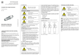
Location in the system
The optimum location in the system depends on the application:
● Liquid applications
For liquid applications the presence of gas or air bubbles in the fluid may result in
erroneous measurements, particularly in the density measurement. Therefore do not
install the flow meter at the highest point in the system, where gas / air bubbles will be
trapped. For liquids it is advantageous to install the flow meter in low pipeline sections, at
the bottom of a U-section in the pipeline.
Figure 4-1 Liquid applications
● Gas applications
For gas applications the presence of oil may result in erroneous measurements.
Therefore do not install the flow meter at the lowest point of the system, or install a filter.
Figure 4-2 Gas applications
/