Page is loading ...

User’s Guide
Direct Digital Video to RGB Video Converter
68-610-01 Rev. A
Printed in the USA
05 02
DVI-RGB 100

DVI-RGB 100 • Installation 3DVI-RGB 100 • Installation
Installation
2
Overview
The DVI-RGB 100 converter converts direct digital video to analog RGB
video. The converter accepts a single link of digital-only Digital Visual
Interface (DVI-D) video from a computer, or other digital video source
device, on a standard 25-pin female DVI-D connector. Digital Flat Panel
(DFP) video can be input via a DFP-to-DVI adapter. The converter
outputs analog RGBHV, RGBS, or RGsB video on five, four, or three
female BNC connectors. The converter also buffers the DVI input and
loops it through on a DVI connector for use by a local monitor (figure 1).
Power High Resolution Workstation
Projector
100-240 50/60 Hz
0.35A MAX
O
U
T
P
U
T
I
N
P
U
T
B
U
F
F
E
R
E
D
L
O
O
P
-
T
H
R
O
U
G
H
R
H
G
V
B
S
SOG ON/OFF
SPARE
D
D
C
S
O
U
R
C
E
M
O
N
I
T
O
R
S
E
L
E
C
T
O
R
O
U
T
P
U
T
R
E
S
O
L
.
DVI-RGB 100
Figure 1 — Typical DVI-RGB 100 application
The video source uses the bidirectional Display Data Channel (DDC) to
determine the video resolution and refresh rate. The video source can
obtain the rate directly from the local monitor or the user can select 1 of
14 resolutions and rates built into the converter.
Level and peaking adjustments allow the user to enhance the RGB video
output for transmission across long distances.
The DVI-RGB 100 is rack mountable and has an internal switching
power supply for worldwide power compatibility.
Rear Panel Connections and Controls
1
Input connector — Connect a single link of direct digital video to
this 25-pin DVI-D connector (figure 2) using the included cable.
2
Buffered Loop-through connector — If desired, connect a direct
digital local monitor to this 25-pin DVI-D connector.
100-240 50/60 Hz
0.35A MAX
OUTPUT
INPUT
BUFFERED
LOOP-THROUGH
R
H
G
V
B
S
SOG ON/OFF
SPARE
DDC
SOURCE
MONITOR
SELECTOR
OUTPUT
RESOL.
21 57
346
Figure 2 — DVI-RGB 100 rear panel
3
Output connectors — Connect an RGB display to these female
BNC connectors.
For RGBHV video — Connect to five
BNC connectors as shown at right.
Ensure that the SOG On/Off switch (
6
) is
turned off.
For RGBS video — Connect to four BNC
connectors as shown at right. Ensure that
the SOG On/Off switch (
6
) is turned off.
For RGsB video — Connect to three BNC
connectors as shown at right. Ensure that
the SOG On/Off switch (
6
) is turned on.
4
DDC Source switch — Set this switch to
the Monitor (up) position to connect the
DDC channel between the direct digital
video source and the local monitor.
Set this switch to the Selector (down) position to connect the DDC
channel between the direct digital video source and the built-in
DVI-RGB 100 DDC logic.
5
Output Resol.(ution) rotary switch — If the DDC Source switch
(
4
) is in the Selector position, set this switch to the appropriate
position to select the desired direct digital video resolution and
refresh rate. The table below identifies the switch positions and
the associated resolutions and vertical refresh rates.
.soPnoituloseRetaR.V.soPnoituloseRetaR.V.soPnoituloseRetaR.V
0084x046065 084x25806A 4201x082106
1084x046576 867x420106B 4201x082157
2006x008067 867x420157C 4201x563106
3006x008578 4201x420106D 027x082106
4084x848069 567x082165F,EerapS
R
H
G
V
B
S
R
H
G
V
B
S
R
H
G
V
B
S

DVI-RGB 100 • Installation and Operation 5DVI-RGB 100 • Installation
Installation
4
Many monitors will not support all of the resolutions and refresh
rates shown. If you get no display, try a different rate.
6
SOG (Sync on Green) On/Off switch— Set this switch to the On
(up) position to enable SOG for RGsB video.
Set this switch to the Off (down) position to disable SOG for
RGBS or RGBHV video.
7
AC power connector — Plug a standard IEC power cord into this
connector to connect the converter to a 100 to 240VAC, 50 Hz or
60 Hz power source.
Installation
1. Power off the computer and its local monitor.
2. For optional rack mounting, mount the converter on a 19" 1U
Universal Rack Shelf (Extron part #60-190-01) (figure 3).
(2) 4-40 x 3/16" Screws
Use 2 Mounting Holes on
Opposite Corners
False Front Panel
uses 2 front holes
D
V
I
-
R
G
B
1
0
0
D
V
I T
O
R
G
B
C
O
N
V
E
R
T
E
R
B
O
O
S
T
L
E
V
E
L
C
O
N
T
R
O
L
P
E
A
K
Figure 3 — Rack mounting the DVI-RGB 100
a. Remove the rubber feet from the case if installed.
b. Mount the converter on the rack shelf, using two 4-40 x 3/16
screws in opposite (diagonal) corners.
c. Install a blank panel (included in the rack kit) or another 1U
half-rack unit on the unused side of the rack.
3. Connect the input, loop-through and output cables. See Rear Panel
Connections and Controls.
The maximum permissible length of the DVI input and output
cables is 16.4 feet (5 meters). Ensure that the cables do not exceed
the maximum permissible length, otherwise images may be
distorted or missing. Extron does not guarantee signal integrity
beyond 16.4 feet.
4. Configure the DDC, Output Resolution, and SOG switches. See
Rear Panel Connections and Controls.
5. Connect power to the DVI-RGB 100.
6. Power on the local monitor and other connected display device(s).
7. Power on the computer
Front Panel Controls and Indicator
DVI-RGB 100
DVI TO RGB CONVERTER
BOOST
LEVEL
CONTROL
PEAK
8 9 10
Figure 4 — DVI-RGB 100 front panel
8
Power LED — The Power LED lights when the DVI-RGB 100 is
receiving power.
9
Level Boost control — The Level Boost control alters the bright-
ness of the picture on the RGB output. Judge the adjustment
visually by looking at the display.
• At the minimum level setting (the counterclockwise limit of
this control), the converter outputs video at 0.5 volts p-p.
• At the control’s midpoint, the converter outputs video at 0.7
volts p-p (unity level).
• At the maximum level setting (the clockwise limit of this
control), the converter outputs video at 1.45 volts p-p.
Select a level setting of 0.7 volts and above to compensate for the
signal level decrease that occurs with long cables. Set the level at
the maximum setting for cable lengths over 500 feet.
Level Boost has no affect on the DVI output of the Buffered Loop-
through connector.

DVI-RGB 100 • Operation 7DVI-RGB 100 • Operation
Indicators and Specifications
6
10
Peak(ing) control — The Peaking control affects the sharpness of
the picture on the RGB output. Increased peaking can
compensate for detail (mid- and high-frequency) loss from low
bandwidth system components or capacitance in long cables. The
minimum setting (at the counterclockwise limit) provides no
peaking. The maximum setting (at the clockwise limit) provides
100% peaking. Adjust this control while viewing the displayed
image to obtain the optimum picture sharpness.
Peaking has no affect on the DVI output of the Buffered Loop-
through connector.
Operation
After the DVI-RGB 100 and its connected devices are powered up, the
system is fully operational. If any problems are encountered, verify that
the cables are routed and connected properly.
The computer reads the DDC on power up to determine the direct
digital video resolution and refresh rate to output. Ensure that
the local DVI monitor and the RGBHV monitor can both display
the selected resolution and refresh rate, otherwise images may be
distorted or missing.
Ensure that the computer and local DVI monitor are connected to
the DVI-RGB 100, and the DVI-RGB 100 and local monitor have
power applied, before applying power to the computer. If the other
devices are not turned on before the computer is, the image will
not appear.
DVI Connector Pin Assignments
Figure 5 and the table below define the DVI pin assignments.
1
9
8
17 24
81
24 17
Female Connector
Male Connector
Figure 5 — DVI connectors
DVI/DFP signals run at a very high frequency and are especially prone
to bad video connections, too many adapters, or excessive cable length.
To avoid the loss of an image or jitter, follow these guidelines:
• Do not exceed 16.4 feet (5 meters) on the input or buffered loop-
through of the converter.
The missing connectors on the included DVI cable are not
required for the single link of DVI-D data supported by the
DVI-RGB 100. These pins are grayed out on the following table.
niP langiS niP langiS niP langiS
1-2ataDSDMT9 -1ataDSDMT71-0ataDSDMT
2+2ataDSDMT01+1ataDSDMT81+0ataDSDMT
3
4/2ataDSDMT
dleihS
11
3/1ataDSDMT
dleihS
91
5/0ataDSDMT
dleihS
4 -4ataDSDMT 21 -3ataDSDMT 02 -5ataDSDMT
5 +4ataDSDMT 31 +3ataDSDMT 12 +5ataDSDMT
6kcolCCDD41rewoPV5+22
kcolCSDMT
dleihS
7ataDCDD51)V5+(dnuorG32+kcolCSDMT
8noitcennoCoN61tceteDgulPtoH42-kcolCSDMT
• Use only the cable designed for DVI signals supplied by Extron.
• Limit or avoid the use of adapters.
• Use only approved DVI/DFP connectors.
CAUTION
Use only cables specifically intended for DVI or DFP
interfaces. Use of non-DVI or non-DFP cables or modified
cables can cause the DVI-RGB 100 to fail.
Specifications
Video
Bit rate (pixel bandwidth) .......... 1.6 gigabits/second/color
Pixel data bit depth ..................... 24 bit
Control data bit depth ................. 6 bit
Maximum resolutions ................. 1280 x 1024 at 85 Hz, 1600 x 1200 at 60 Hz
Video input
Number/signal type ................... 1 DVI-D digital video
Connectors .................................... 1 DVI-D female (DVI input)
1 DVI-D female (DVI loop through)
Minimum/maximum levels ...... 0.5V to 1.0V p-p
Impedance .................................... 50 ohms
Maximum DC offset .................... ±0.5V
Video output
Number/signal type ................... 1 RGBHV, RGBS, RGsB
Connectors .................................... 6 BNC female

Extron Electronics, USA
1230 South Lewis Street
Anaheim, CA 92805
USA
714.491.1500
Fax 714.491.1517
Extron Electronics, Europe
Beeldschermweg 6C
3821 AH Amersfoort
The Netherlands
+31.33.453.4040
Fax +31.33.453.4050
Extron Electronics, Asia
135 Joo Seng Road, #04-01
PM Industrial Building
Singapore 368363
+65.6383.4400
Fax +65.6383.4664
Extron Electronics, Japan
Daisan DMJ Building 6F
3-9-1 Kudan Minami
Chiyoda-ku, Tokyo 102-0074 Japan
+81.3.3511.7655
Fax +81.3.3511.7656
www.extron.com
© 2002 Extron Electronics. All rights reserved.
Minimum/maximum levels ...... 0.7V to 1.4V p-p (continuously adjustable)
Impedance .................................... 75 ohms
Return loss .................................... -35dB @ 5 MHz
DC offset ....................................... ±5mV maximum with input at 0 offset
Sync
Output type .................................. RGBHV, RGBS, RGsB
Output level .................................. TTL (5V p-p) (unterminated)
Output impedance ....................... 75 ohms
Polarity .......................................... Positive or negative (follows input)
General
Power ............................................. 100VAC to 240VAC, 50/60 Hz, 25 watts, internal,
auto-switchable.
Product requires 0.15 A to 0.3 A.
Temperature/humidity .............. Storage -40° to +158°F (-40° to +70°C) / 10% to
90%, non-condensing
Operating +32° to +122°F (0° to +50°C) / 10% to
90%, non-condensing
Rack mount................................... Yes, with optional rack shelf, part #60-190-01
Enclosure type .............................. Metal
Enclosure dimensions ................. 1.7" H x 8.7" W x 6.0" D (1U high, half rack
width)
4.3 cm H x 22.1 cm W x 15.2 cm D
(Depth excludes connectors and knobs.)
Product weight ............................. 1.6 lbs (0.7 kg)
Shipping weight .......................... 4 lbs (1.8 kg)
Vibration ....................................... ISTA/NSTA 1A in carton (International Safe
Transit Association)
Listings .......................................... UL, CUL
Compliances ................................. CE, FCC Class A, VCCI, AZ/NZS, ICES
MTBF ............................................. 30,000 hours
Warranty ....................................... 3 years parts and labor
Specifications are subject to change without notice.
Optional Adapters and Cables
• 26-497-01 DVI (male), DFP (female)
• 26-498-01 DVI (female), DFP (male)
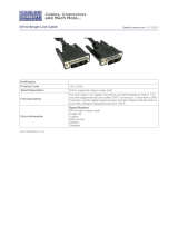
• 26-535-01 DVI-D M-M extension cable, 6.6’
• 26-535-02 DVI-D M-M extension cable, 9.9’
/