Xeno

MULTIPLEX Xeno Quick start guide

  • Hello! I am an AI chatbot trained to assist you with the MULTIPLEX Xeno Quick start guide. I’ve already reviewed the document and can help you find the information you need or explain it in simple terms. Just ask your questions, and providing more details will help me assist you more effectively!
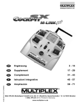
QuickStart Guide for MPX RR models & MPX Cockpit SX
MULTIPLEX Modellsport GmbH & Co.KG • Westliche Gewerbestraße 1 • D-75015 Bretten • www.multiplex-rc.de Page 1/2
QuickStart Guide # 82 5480 (28-03-11/JES) • Errors and omissions excepted! • ¤ MULTIPLEX
1st MPX RR MODEL
I. Install Multiplex receiver in the model
Follow the instructions supplied with the model.
II. Connect the servos according to the Multiplex sequence
Servo sequence:
Note: The servo assignment is not always clear at the early stage. The important
point is to assign the speed controller correctly, to avoid any danger of the motor
starting up accidentally. The control surface servos can be assigned later.
III. Install the battery (do not connect it!) and check the Centre of Gravity
Observe the position stated in the model instructions.
2nd COCKPIT SX M-LINK RADIO CONTROL SYSTEM
I. Prepare the Cockpit SX transmitter
I.I. Transmitter with
model memory
-> move to II.
I.II. Transmitter with empty model memory
- Download Multiplex Launcher from MPX site
- Install Launcher on PC
- Use Launcher to transfer the memory contents to the
transmitter
II. Select the model memory at the Cockpit SX
At the „GO TO“ point of the (MEMO) menu:
Use the round 3D digi-adjuster in the centre of the transmitter.
(Functions: left 4 & right 3 and press r)
1x 4 to MENU, ..................1x r (SETUP appears)
4x 3 to MEMO, ..................1x r (GO TO appears)
1x r (0 appears, flashing)
3 Select model .................r (concludes select process)
ĺ Memory name and transmitter voltage displayed; Select process concluded.
III. Set stick mode (which stick controls what?)
Note: You will find a list and explanation of the stick modes on the back under
“Notes & explanations, Selecting the stick mode”.
1x 4 to MENU, ..................1x r (SETUP appears)
1x r (MODEL appears),.....1x r (MODE appears)
1x r (number, flashing)
Select MODE....................1x r (Select process concluded)
ĺ Switch transmitter off!
3rdBIND TRANSMITTER TO RECEIVER
I. Prepare the transmitter for binding
- Hold the 3D digi-adjuster on the transmitter pressed in and switch the transmitter on.
- Now turn the 3D digi-adjuster to the right 3 as far as BIND, then press the button r
(BIND appears).
ĺ Binding procedure started, beep sequence emitted, transmitter LED flashes fast
II. Prepare receiver for binding
- Switch receiver ON, or connect the battery.
- Press the SET button on the top of the receiver for at least ten seconds until the
LED goes out.
- Only now release the SET button.
ĺ Binding procedure initiated, the LED on the receiver flashes fast.
Note
: transmitter power is greatly reduced for the binding process; reduce the
distance between the model and the transmitter to 50 cm or less.
III. Binding procedure concluded
Once bound, the transmitter and receiver automatically switch to regular operation:
the LEDs flash slowly, and the transmitter screen displays the name of the selected
model and the transmitter battery’s voltage.
4th CONTROL SURFACE NEUTRAL POSITIONS
Switch on the transmitter and receiver, and check the neutral position of the control
surfaces.
This is accomplished by moving all the sticks to the neutral position, with the
exception of the throttle (motor off). Push the right-hand slider forward (if using one of
the stick modes 5 - 8 pull it back, as this is the throttle), and select Flight Phase 2.
Use key to loosen the grubscrews in the swivel connectors, set the control surfaces to
neutral, then re-tighten the screws firmly.
Exception: if your model is the Multiplex FunCopter, select Flight Phase 1, and follow
the instructions in the section entitled “Checking the working systems, settings”.
QuickStart Guide for MPX RR models & MPX Cockpit SX
MULTIPLEX Modellsport GmbH & Co.KG • Westliche Gewerbestraße 1 • D-75015 Bretten • www.multiplex-rc.de Page 2/2
QuickStart Guide # 82 5480 (28-03-11/JES) • Errors and omissions excepted! • ¤ MULTIPLEX
5th EXPLANATION OF SERVO FUNCTIONS, AND HOW TO CHECK THEM
Note: If any control surface moves in the wrong “sense” (direction), return to
Section 1. “Connecting servos according to the Multiplex sequence”.
centre
off
left
back
right
forwa
r
Ailerons:
Roll:
in line with wing
Swashplate exactly level
left up right down
Swashplate tilt to the left
left down right up
Swashplate tilt to the right
Rudder:
Yaw:
in line with fin
undefined!
moves left
tail rotor pushrod move
towards
moves right
tail rotor pushrod move
forward
Elevator:
Pitch axis:
horizontal
Swashplate exactly level
moves up
Swashplate tilt forward
moves down
Swashplate tilt towards
Throttel:
motor off
Caution:
half-throttle
Caution:
full-throttle
6th FUNCTIONS / MIXERS OF MPX MODEL MEMORIES
Airplane Helicopter
Combi-Switch* Flight phase 4:
Hover
Dual-Rate** Dual-Rate**
THR-CUT
Emergency throttle CUT
no function
Flight phases for gliders:
3:speed
2:normal
1:thermal
Flight phases:
3:Hover
2:Cruise
1:Hover
right-hand slider:
Spoiler***
or Throttel
no function
Trim buttons
On/Off switch
3-D digi-adjustor
*Combi-Switch: same-side rudder mixed in with ailerons. **Dual-
Rate: aileron / elevator / rudder, switches between two travel
settings.
***Spoiler: ailerons up or down acting as landing aid.
7th PREPARATION, FIRST FLIGHT
- Move the Dual Rate switch to the bottom position to give reduced control surface
travels, then select Flight Phase 2 for a fixed-wing model, or Flight Phase 1 for a
helicopter
- Use Fail-Safe (See “Notes & explanations, Fail-Safe”).
- It is essential to carry out a range-check before the first flight, as described in the radio
control system instructions.
- Allow the model to gain height briskly immediately after launch, so that you can check
the model’s trims (see “Notes and explanations, trimming”).
All of us in the MULTIPLEX team hope you have many hours of pleasure and success
flying your new model.
8th NOTES & EXPLANATIONS
I. Selecting the stick mode
The stick mode determines which transmitter control operates the functions aileron,
elevator, rudder, throttle and spoiler. Modes 1 - 4 are available for model helicopters,
and Modes 1 - 8 for fixed-wing models. If you are a beginner, we recommend that you
assign THROTTLE to one of the sticks.
Stick mode table:
Mode
left stick
ÕÖ ×Ø
right stick
ÕÖ ×Ø
right
slider
<
Mode
left stick
ÕÖ ×Ø
right stick
ÕÖ ×Ø
right
slider
1 Rudder Elevator Aileron Throttle 5 Rudder Elevator Aileron Spoiler
2 Rudder Throttle Aileron Elevator 6 Rudder Spoiler Aileron Elevator
3 Aileron Elevator Rudder Throttle 7 Aileron Elevator Rudder Spoiler
4 Aileron Throttle Rudder Elevator
Spoiler
8 Aileron Spoiler Rudder Elevator
Throttle
Once you have decided on a stick mode, you must disable the centring spring on the
throttle stick to prevent it returning to the neutral position automatically.
See page 12 of the Cockpit SX operating instructions for directions.
II. Fail-Safe
Use the transmitter to set all the servos (and the speed controller) to the neutral
position, then briefly press the SET button on the receiver (0.5 to 1 second). This
action stores the current servo positions, and the LED flashes in confirmation.
ĺ If interference affects the radio link, the servos run to these defined positions until
reception is restored.
III. Trims
The trim buttons are positioned close to the sticks. They are used to adjust the servo
centre positions / control surface neutral positions.
This may be necessary if, for example, your model climbs, dives or veers to one side
instead of flying straight, even though you are holding the sticks at centre. Correct the
model’s trim by moving the trims in the direction opposite to the direction of flight
which you wish to correct. The settings are automatically stored.
IV. What to do if “THROTTLE>0” appears on the screen?
Throttle-check is a safety query for the throttle control; the function prevents the motor
starting up accidentally when you switch the transmitter on.
The transmitter’s screen displays “THROTTLE>0” until you move the throttle control
back to the Idle position. Only then is the transmitter ready for use.
/