Sub-Zero IW30RH Installation guide

Type
Installation guide
WINE STORAGE
INSTALLATION GUIDE
SPECIFICATIONS, INSTALLATION, AND MORE
2 | Sub-Zero Customer Care 800.222.7820
WINE STORAGE
Contents
3 Wine Storage
4 Opening Dimensions
5 Electrical
6 Plumbing
6 Preparation
6 Anti-Tip Bracket
8 Placement
8 Alignment
9 Water Line
10 Custom Panels
12 Panel Installation
14 Completion
Features and specications are subject to change at any
time without notice. Visit subzero.com/specs for the most
up-to-date information.
Important Note
To ensure this product is installed and operated as safely
and efciently as possible, take note of the following types
of highlighted information throughout this guide:
IMPORTANT NOTE highlights information that is especially
important.
CAUTION indicates a situation where minor injury or product
damage may occur if instructions are not followed.
WARNING states a hazard that may cause serious injury or
death if precautions are not followed.
IMPORTANT NOTE: Throughout this guide, dimensions in
parentheses are millimeters unless otherwise specied.
IMPORTANT NOTE: Save these instructions for the local
electrical inspector.
subzero.com | 3
Product Information
Important product information, including the model and
serial number, are listed on the product rating plate. The
rating plate is located on the handle side wall, directly below
the control panel. Refer to the illustration below.
If service is necessary, contact Sub-Zero Factory Certied
Service with the model and serial number. For the name
of the nearest Sub-Zero Factory Certied Service or for
questions regarding the installation, visit the Support &
Service section of our website, subzero.com, or call
Sub-Zero Customer Care at 800-222-7820.
WINE STORAGE
Tools and Materials
Screwdrivers—standard, Phillips, and Torx.
Power drill.
Drill bits (masonry bits required for concrete installation).
Standard socket and wrench set.
2' and 4' levels.
Tubing cutter.
3'
(.9 m) of
1
/4" OD copper, braided stainless steel, or
PEX tubing.
Saddle valve.
Material to protect home, ooring, and cabinetry during
installation.
Rating plate location
RATING PLATE
4 | Sub-Zero Customer Care 800.222.7820
SITE PREPARATION
Opening Dimensions
WINE STORAGE
OPENING DIMENSIONS
W
18" Model 18" (457)
24" Model 24" (610)
30" Model 30" (762)
The depth of each wine storage model is 24" (610). Allow for
panel thickness when planning the nished opening depth.
A minimum 3
1
/2" (89) nished return is required on all sides
of the opening. Framed cabinets will require additional
nished ller material behind the face frame for a proper
installation. Refer to the illustration.
DUAL INSTALLATION
When installing two units side by side in a dual installa-
tion, the opening width is the width of the two units added
together. A dual installation kit is required for this installa-
tion. If a dual installation kit is not specied, a minimum
2"
(51) ller strip is required between the units.
Dual installation kits are available through an authorized
Sub-Zero dealer. For local dealer information, visit the nd
a showroom section of our website, subzero.com. For
questions regarding the installation, call Sub-Zero Customer
Care at 800-222-7820.
W
OPENING WIDTH
84"
(2134)
OPENING
HEIGHT
NOTE:
3
1
/2" (89) finished returns will be visible and should be finished to match cabinetry.
SIDE
VIEW
TOP VIEW
FRONT VIEW
3
/4" (19)
TYPICAL
FRAMED
CABINETRY
W
FILLER
3
1
/2" (89)
FINISHED
RETURN
FRAMELESS
CABINETRY
W
3
/4" (19)
TYPICAL
3
1
/2" (89)
FINISHED
RETURN
25" (635)
OPENING
DEPTH
subzero.com | 5
SITE PREPARATION
HOME SECURITY CONNECTION
If the unit will be connected to a home security system, low-
voltage leads must be provided to the unit. Two connectors
are located behind the top trim. Provide 10'
(3 m) minimum
lead wires for each connector, exiting the back wall near the
electrical receptacle.
Remove the top trim by disengaging the trim from the hinge
side of the unit. Rotate the trim and remove the trim pin from
the handle side vertical support. Refer to the illustrations
below. Use spade terminals or wire nuts to make proper
wiring connections. Refer to the following color codes:
Normally open contacts—white with red stripe wire.
Common—gray with white stripe wire.
CAUTION
The alarm circuit in the unit is intended as a low-
voltage, low-current device only. It should not be used
to switch line power. Any unused terminals should be
completely insulated and all wires should be secured
away from conductive or moving components.
Electrical Requirements
Installation must comply with all applicable electrical codes.
The electrical supply must be located within the shaded
area shown in the illustration and chart below. A separate
circuit servicing only this appliance is required. A ground
fault circuit interrupter (GFCI) is not recommended and may
cause interruption of operation.
The electrical outlet must be positioned with the grounding
prong to the right of the thinner blades.
CAUTION
The outlet must be checked by a qualied electrician
to be sure it is wired with the correct polarity. Verify the
outlet is properly grounded.
WARNING
Do not use an extension cord, two-prong adapter, or
remove the power cord ground prong.
ELECTRICAL REQUIREMENTS
Electrical Supply 115 VAC, 60 Hz
Service 15 amp dedicated circuit
Receptacle 3-prong grounding-type
ELECTRICAL SUPPLY LOCATION
A
18" Model 6" (152)
24" Model 9
1
/2" (241)
30" Model 12
1
/2" (318)
A
1
/4" (6)
1
/4" (6)
4
1
/4"
(108)
4
1
/2"
(114)
FLOOR
LEFT SIDE
OF OPENING
Electrical supply location
PIN
Top trim—hinge side
Top trim—handle side
6 | Sub-Zero Customer Care 800.222.7820
Preparation
Uncrate the unit and inspect for damage. Remove the wood
base and discard the shipping bolts and brackets. Remove
and recycle packing materials. Do not discard the kickplate,
anti-tip bracket, and hardware.
Remove the kickplate by extracting the two mounting
screws. Refer to the illustration below.
Anti-Tip Bracket
WARNING
To prevent the unit from tipping forward, the anti-tip
bracket must be installed.
The back of the anti-tip bracket must be installed 24" (610)
from the front of the unit (without panels). Use all anti-tip
bracket hardware as instructed for wood or concrete oors.
IMPORTANT NOTE: For wood or concrete oor applications,
if the #12 screws do not hit a wall stud or wall plate, use the
#8 screws and #12 washers with the wall anchors.
IMPORTANT NOTE: In some installations, the subooring or
nished oor may necessitate angling the screws used to
fasten the anti-tip bracket to the back wall.
SITE PREPARATION
SCREW
Kickplate removal
Plumbing Requirements
Installation must comply with all applicable plumbing codes.
For model IW-30CI, the water supply line should be located
within the shaded area shown in the illustration below.
The water supply line should be connected to the house
supply with an easily accessible shut-off valve. Do not use
self-piercing valves. The water supply line must be ush to
the oor and not interfere with the installation of the anti-tip
bracket.
A reverse osmosis system can be used provided there is
constant water pressure of 35–120 psi
(2.4–8.3 bar) supplied
to the unit at all times. In this application, the water ltra-
tion system must be bypassed. Refer to Water Filter Bypass
on page 15. A copper line is not recommended for this
application.
PLUMBING REQUIREMENTS
Water Supply Line
1
/4" OD copper, braided
stainless steel, or PEX tubing
Water Pressure 35–120 psi
(2.4–8.3 bar)
Excess Water Line for Connection 36" (914)
WATER SUPPLY LOCATION
A
IW-30CI 6" (152)
3" (76)
6" (152)
RIGHT SIDE
OF OPENING
AREA EXTENDS
1
/2" (13)
FORWARD ON FLOOR
A
Water supply location (IW-30CI)
subzero.com | 7
SITE PREPARATION
CONCRETE WEDGE ANCHOR INSTALLATION
1 Drill a
3
/8" (10) diameter hole any depth exceeding the
minimum embedment. Clean the hole or drill additional
depth to accommodate the drill nes.
2 Assemble the washer and nut ush with the end of
anchor to protect threads. Drive the anchor through the
material to be fastened until the washer is ush with the
surface material.
3 Expand the anchor by tightening the nut 3–5 turns past
hand-tight position or to 25 foot-pounds of torque.
WARNING
Verify there are no electrical wires or plumbing in the
area which the screws could penetrate.
CAUTION
Always wear safety glasses and use other necessary
protective devices or apparel when installing or working
with anchors.
Anchors are not recommended for use in lightweight
masonry material such as block or brick, or for use in
new concrete which has not had sufcient time to cure.
The use of core drills is not recommended to drill holes
for the anchors.
Anti-Tip Bracket
WOOD FLOOR APPLICATION
After properly locating the anti-tip bracket in the opening,
drill pilot holes
3
/16" (5) diameter maximum in the wall studs
or wall plate. Use the #12 screws and washers to secure the
brackets. Verify the screws penetrate through the ooring
material and into the wall studs or wall plate a minimum of
3
/4" (19). Refer to the illustration and chart below.
CONCRETE FLOOR APPLICATION
After properly locating the anti-tip bracket in the opening,
drill pilot holes
3
/16" (5) diameter maximum in the wall studs
or wall plate. Drill
3
/8" (10) diameter holes into the concrete
a minimum of 1
1
/2" (38) deep. Use the #12 screws and
washers to secure the brackets to the wall, and use the
3
/8"
wedge anchors to secure the brackets to the oor. Verify the
screws penetrate the wall studs or wall plate a minimum of
3
/4" (19). Refer to the illustration and chart below.
ANTI-TIP BRACKET PLACEMENT
A
18" Model 9" (229)
24" Model 12" (305)
30" Model 15" (381)
A
A
SUBFLOORING
WOOD FLOOR
WALL PLATE
FINISHED
FLOORING
A
A
SUBFLOORING
CONCRETE
FLOOR
WALL PLATE
FINISHED
FLOORING
1
1
/2"(38)
min
Wood oor
Concrete oor
8 | Sub-Zero Customer Care 800.222.7820
INSTALLATION
Placement
CAUTION
Before moving the unit into position, secure the door/
drawers closed and protect any nished ooring.
Use an appliance dolly to move the unit near the opening.
The front leveling legs are extended below the front rollers to
improve stability during placement. Once the unit is placed
in front of the opening, completely retract the front leveling
legs to allow the unit to be rolled into position. The front and
rear leveling legs can be adjusted from the front once the
unit is positioned.
If the unit has been on its back or side, it must stand upright
for a minimum of 24 hours before connecting power.
Plug the power cord into the grounded outlet and roll the
unit into position. Verify the anti-tip bracket is properly
engaged.
Alignment
LEVELING
Once the unit is in position, the height adjustment can be
made from the front. Using a Phillips drive, turn clockwise to
raise the unit or counterclockwise to lower. Use the lowest
torque setting when using a power drill. Do not turn the
leveling legs by hand. Refer to the illustration below.
When the unit is properly leveled, door/drawer adjustments
are less likely to be necessary.
IMPORTANT NOTE: Level the unit to the oor, not the sur-
rounding cabinetry. This could affect the operation of the
unit, such as door closing.
WARNING
To reduce the possibility of the unit tipping forward, the
front leveling legs must be in contact with the oor.
REAR
ADJUSTMENT
FRONT
ADJUSTMENT
Leveling
subzero.com | 9
INSTALLATION
Water Line
For model IW-30CI, approximately 3' (.9 m) of
1
/4" plastic
tubing is connected to the unit with a preassembled
1
/4"
compression connection under the unit. The water line t-
ting connection kit, provided with the unit, contains a
1
/4"
compression union tting for connection to the household
water line.
Purge the water line prior to nal connection to the unit. This
will remove any debris that may be present in the tubing
from installing the new water line. Connect the plastic tubing
from the unit to the house water supply line with the tting
connection kit provided. Check all water line ttings for
leaks.
Locate the water line in the notch as shown in the illustration
below.
IMPORTANT NOTE: If a reverse osmosis system is used, it
is recommended the water ltration system be bypassed by
removing the lter.
IMPORTANT NOTE: Water lines cannot be exposed to
freezing temperatures.
WATER LINE
CONNECTION
NOTCH
Water line (IW-30CI)
Alignment
ANCHORING
Adjust the depth of the unit to t ush with the surrounding
cabinetry. Once aligned, verify the door/drawers open prop-
erly, then install the screws in each side trim.
FRONT OF
UNIT
CABINETRY
FACE
FRAME
PANEL
THICKNESS
SCREW
SIDE TRIM
Anchoring
10 | Sub-Zero Customer Care 800.222.7820
Custom Panels
Custom door/drawer panels and handle hardware must
be installed. Stainless steel panels are available through an
authorized Sub-Zero dealer. For local dealer information,
visit the nd a showroom section of our website,
subzero.com.
The thickness of the custom panel can vary. A minimum
5
/8" (16) thick panel is required, but the thickness can be
increased provided it does not exceed the maximum panel
weight indicated in the chart below. The depth of each
model is 24"
(610). Allow for panel thickness when planning
the nished opening depth.
PANEL REQUIREMENTS
WEIGHT PER PANEL MAX
Door (column model) 35 lb (16 kg)
Door (tall model) 25 lb (11 kg)
Drawer 15 lb (7 kg)
PANEL THICKNESS MIN
All Panels
5
/8" (16)
Reveals between panels can vary,
1
/8" (3) reveals are typical.
CAUTION
When installing a panel thicker than 1" (25), the 90°
door stop may be required to prevent damage to the
unit and adjacent cabinetry.
CAUTION
As reveals between cabinetry and the unit decrease,
severe nger pinching can occur while the door is
closing.
Finish all sides of the custom panels. They will be visible
when the door is open.
D-style handles are recommended. Locate the door handle
near the edge of the panel opposite the hinge and centered
top to bottom. Locate the drawer handles near the top edge
of each panel. Stainless steel tubular and pro handles are
avail able through an authorized Sub-Zero dealer. For local
dealer information, visit the nd a showroom section of our
website, subzero.com.
PANEL INSTALLATION
subzero.com | 11
PANEL INSTALLATION
Custom Panels
DOOR PANEL HEIGHT
The height of the custom door panel can extend beyond the
typical panel height, provided it does not exceed the weight
limit. Refer to the illustration below.
1
3
/4"
(45)
A DECORATIVE VALANCE
CANNOT EXTEND
BEYOND THIS PLANE
DOOR
PANEL
HINGE
24" (610)
TO BACK OF UNIT
84"
(2134)
1
/8" (3)
Upper valance (side view)
TOE KICK CLEARANCE
The height of the toe kick area can extend beyond the
typical toe kick height, provided it does not exceed the
dimensions in the illustration below. Toe kick heights from
2"
(51) to 3
7
/8" (98) require a reduced toe kick accessory
available through an authorized Sub-Zero dealer. For local
dealer information, visit the nd a showroom section of our
website, subzero.com. For questions regarding the installa-
tion, call Sub-Zero Customer Care at 800-222-7820.
24" (610)
TO BACK OF UNIT
VENTED
LOUVERS
HINGE
**
DOOR
PANEL
1
1
/8" (29)
MAX
TOE KICK
ADJUSTMENT
A DECORATIVE TOE KICK
CANNOT EXTEND
BEYOND THIS PLANE
2" (51)*
TO
6" (152)
FROM
FLOOR
*2" (51) to 3
7
/8" (98) requires sales accessory.
**Column models only.
Toe kick (side view)
12 | Sub-Zero Customer Care 800.222.7820
PANEL INSTALLATION
Panel Installation
DOOR PANEL
Typical panel dimensions are based on an 84" (2134) nished
height with
1
/8" (3) reveals. Placement of the template must
be adjusted for panels exceeding the typical dimensions.
For tall models, the door panel should be installed rst,
followed by the upper, then lower drawer panel.
Place the panel face down on a protected work surface.
Position the template ush with the top and sides of the
panel. Verify the correct side of the template is being used,
then mark and drill holes. Refer to the illustration below.
For tall models, align the notch in the template with the
bottom of the door panel, then mark and drill holes. Refer to
the illustration below.
Use a Torx drive to partially insert a #8 x
1
/2" screw into the
second hole from the top on each side of the panel. The
screws should be approximately
3
/16" (4) proud of the panel
and will support the weight of the panel during installation.
Align the support screws on the back of the panel with the
slotted holes on both door mounting brackets. Refer to
the illustration below. Opening the door slightly may help
with alignment. Once the panel is supported by the screws,
partially insert a #8 x
1
/2" screw into the second hole from
the bottom on each side of the panel, but do not tighten.
CAUTION
As reveals between cabinetry and the unit decrease,
severe nger pinching can occur while the door is
closing.
BACK OF
DOOR PANEL
Door panel mounting
BOTTOM OF
DOOR PANEL
EDGE OF DOOR PANEL
USE TABS FOR HINGE
SIDE PANEL EDGE ON
DUAL INSTALLATION
TOP OF
DOOR PANEL
84" APPLICATION
83 7/8" ACTUAL
EDGE OF DOOR PANEL
TOP OF DOOR PANEL
BOTTOM OF
DOOR PANEL
EDGE OF DOOR PANEL
USE TABS FOR HINGE
SIDE PANEL EDGE ON
DUAL INSTALLATION
TOP OF
DOOR PANEL
84" APPLICATION
83 7/8" ACTUAL
EDGE OF DOOR PANEL
BOTTOM OF
DOOR PANEL
Door panel template—top
Door panel template—bottom
(tall model)
subzero.com | 13
PANEL INSTALLATION
PANEL ADJUSTMENT
Close the door/drawers, now adjustments can be made to
align the panels and reveals.
For side-to-side adjustment, move the panels side to side,
then install and tighten all mounting screws.
For up-and-down and in-and-out adjustments, slightly
loosen the bracket screws. Depending on the level of
adjustment required, it may be helpful to loosen all of the
bracket screws which will allow for maximum adjustment.
Once the bracket screws are loosened, use a wrench to
rotate the cams to make adjustments. After the adjustments
have been made, tighten all bracket screws. Refer to the
illustrations below.
BRACKET
SCREWS
IN-AND-OUT
CAM
BRACKET
SCREWS
UP-AND-DOWN
CAM
In-and-out adjustment
Up-and-down adjustment
Panel Installation
DRAWER PANELS—TALL MODEL
Place the panel face down on a protected work surface.
Position the template ush with the top and sides of the
panel. Verify the correct side of the template is being used,
then mark and drill holes. Refer to the illustration below.
Use a Torx drive to partially insert a #8 x
1
/2" screw into the
second hole from the top on each side of the panel. The
screws should be approximately
3
/16" (4) proud of the panel
and will support the weight of the panel during installation.
Align the support screws on the back of the panel with the
slotted holes on both drawer mounting brackets. Refer to
the illustration below. Opening the drawer slightly may help
with alignment. Once the panel is supported by the screws,
partially insert a #8 x
1
/2" screw into the second hole from
the bottom on each side of the panel, but do not tighten.
RIGHT EDGE OF DRA
WER PANEL
TOP HOLES
FOR UPPER
AND LOWER
DRAWERS
BOTTOM
HOLES FOR
LOWER
DRAWER
BOTTOM
HOLES FOR
UPPER
DRAWER
7021340
TOP OF
DRAWER PANEL
LEFT EDGE OF DRAWER PANEL
TOP OF DRAWER PANEL
BACK OF
DRAWER PANEL
Drawer panel template—top
Drawer panel mounting
14 | Sub-Zero Customer Care 800.222.7820
INSTALLATION
Completion
DOOR TRIM INSTALLATION
After the panels have been adjusted, install the decorative
side trim to the door/drawers. To install, start at the top and
align the trim with the front and rear anges on the bracket,
then snap into place by pushing the trim toward the back
of the panel. Once the top is secure, continue the installa-
tion downward until the remaining trim is completely secure.
Refer to the illustrations below.
SIDE TRIM INSTALLATION
Install the decorative trim strip to the handle side of tall
and column models. The side trim snaps over the bracket
attached to the handle side of the unit. Refer to the illustra-
tion below.
Side trim
TOP TRIM INSTALLATION
Identify the top trim strips by the notch on one end at the
bottom; this trim strip ts on the hinge side of the unit.
Insert the outer end of each trim strip behind the vertical
side trim. Engage the snap in the plastic side bracket and
slide the panel as far to the outside as possible. Refer to the
illustration below.
Rotate the inner end of each panel into the side ange of
the center shroud, next to the water lter access door. Press
on the trim strip to snap into place. Refer to the illustration
below.
Inner top trim
Outer top trim
SIDE TRIM
FRONT
FLANGE
REAR
FLANGE
Door side trim
Bracket anges
subzero.com | 15
INSTALLATION
WATER FILTER BYPASS
If the water ltration system will not be used, it can be
placed in water lter bypass mode by removing the water
lter. Follow these steps to remove the water lter:
1 Pull out on the bottom edge of the access door and tilt
upward.
2 To remove the lter, rotate counterclockwise one-quarter
turn, then pull out. Refer to the illustration below.
WARNING
Follow all city and state laws when storing, recycling,
or discarding unused refrigerators and freezers.
Completion
KICKPLATE INSTALLATION
Position the kickplate and install using the two mounting
screws. Refer to the illustration below. Kickplate must
be removable for service. The oor cannot interfere with
removal.
A maximum 6"
(152) decorative kickplate can be attached
to the factory-installed kickplate. The two rows of vented
louvers can be covered if the door panel is a minimum 4"
(102)
from nished oor.
To install a decorative kickplate, remove the paper backing
from the magnets and attach the decorative kickplate to the
magnets. The magnets allow the decorative kickplate to be
removed if necessary.
Turn power on by touching “power” on the control panel.
90° DOOR STOP
A 105° door stop is built into the hinges. To limit the door
swing to 90°, open the door slightly less than 90°, then use
a standard screwdriver blade to remove the existing clips
from each hinge. Locate the 90° clips from inside the plastic
bag containing the product literature, then insert the 90°
clips onto each hinge. Refer to the illustration below.
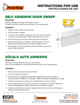
SCREWMAGNET
CLIP
Kickplate installation
90° door stop
WATER FILTER
ACCESS DOOR
Water lter removal (IW-30CI)
Sub-Zero, Sub-Zero & Design, Sub-Zero & Snowake Design, Dual Refrigeration, The Living Kitchen, Great American Kitchens The Fine Art of Kitchen Design, Wolf, Wolf &
Design, Wolf Gourmet, W & Design, red colored knobs, Cove, and Cove & Design are registered trademarks and service marks of Sub-Zero Group, Inc. and its subsidiaries.
All other trademarks are property of their respective owners in the United States and other countries.
  • Page 1 1
  • Page 2 2
  • Page 3 3
  • Page 4 4
  • Page 5 5
  • Page 6 6
  • Page 7 7
  • Page 8 8
  • Page 9 9
  • Page 10 10
  • Page 11 11
  • Page 12 12
  • Page 13 13
  • Page 14 14
  • Page 15 15
  • Page 16 16
  • Page 17 17
  • Page 18 18
  • Page 19 19
  • Page 20 20
  • Page 21 21
  • Page 22 22
  • Page 23 23
  • Page 24 24
  • Page 25 25
  • Page 26 26
  • Page 27 27
  • Page 28 28
  • Page 29 29
  • Page 30 30
  • Page 31 31
  • Page 32 32
  • Page 33 33
  • Page 34 34
  • Page 35 35
  • Page 36 36
  • Page 37 37
  • Page 38 38
  • Page 39 39
  • Page 40 40
  • Page 41 41
  • Page 42 42
  • Page 43 43
  • Page 44 44

Sub-Zero IW30RH Installation guide

Type
Installation guide

Ask a question and I''ll find the answer in the document

Finding information in a document is now easier with AI