Lincoln Electric K4071-1 User manual
- Category
- Bicycle accessories
- Type
- User manual
This manual is also suitable for

• Sales and Service through Subsidiaries and Distributors Worldwide •
2345 Murphy Blvd. Gainesville, GA 30504 TEL: 866-236-0044
• World's Leader in Welding and Cutting Products •
AUTO-DARKENING HELMET
OPERATOR’S MANUAL
IM10196
May 2014
Copyright © Lincoln Global Inc.
TABLE OF CONTENTS Page
SAFETY WARNINGS – READ BEFORE USING 1
HELMET INFORMATION 2
SPECIFICATIONS 3
OPERATING INSTRUCTIONS 4
CARTRIDGE OPERATIONS/FEATURES 5
SHADE GUIDE SETTINGS 6
HELMET CARE AND MAINTENANCE 7
TROUBLE SHOOTING 8
WARRANTY INFORMATION 9
REPLACEMENT PARTS 9

HELMET INFORMATION
This Auto-Darkening Welding Helmet will automatically change from a light
state (shade 3.5) to a dark state (Shade 9-13) when arc welding starts.
The filter automatically returns to a light state when the arc stops.
Shade control adjustments can be made while welding.
Match your welding application to the shade indicated on the shade chart.
(See Page 6)
• Operating temperature: 14°F ~ 131°F (-10°C ~ 55°C).
• Do not use or open the auto-darkening filter if damaged by shock, vibra-
tion or pressure.
• Keep the sensors and solar cell clean. Clean the filter cartridge using a
soapy water solution and soft cloth which should be damp but not saturat-
ed.
This Auto-Darkening Welding Helmet is designed for use with GMAW, GTAW,
MMAW welding, or Plasma Arc and air carbon arc cutting.
The cartridge provides protection from harmful UV and IR radiation, in both
dark and light states.
The cartridge contains two sensors to detect the light from the welding arc,
resulting in the lens darkening to a selected welding shade.
• Do not use solvents or abrasive cleaning detergent.
• If cover lens is spattered or covered with dirt, it should be replaced imme-
diately.
• Use only replacement parts specified in this manual.
• Do not use the helmet without inside and outside cover lenses properly
installed.
2
SAFETY WARNINGS – READ BEFORE USING
ARC Rays can injure eyes and burn skin
• Before welding, always inspect helmet and filter lens to be sure they are fitted
properly, in good condition and not damaged.
• Check to see that the clear lens is clean and securely attached to the helmet.
• Always wear safety glasses or goggles under the welding helmet and protective
clothing to protect your skin from radiation, burns and spatter.
• Ensure that optical radiation from other welder’s arcs in the immediate area
does not enter in from behind the helmet and auto-darkening filter.
Note: Auto-darkening filters in Lincoln helmets are designed to protect the user against harmful
ultra-violet and infrared rays both in the dark and light states. No matter what shade the filter is
set to, the UV/IR protection is always present.
FUMES AND GASES can be dangerous to your health.
• Keep your head out of fumes.
• Use enough ventilation or exhaust at the arc or both to keep fumes and gases
from your breathing zone and general area.
• When welding with electrodes which require special ventilation such as
stainless or hard facing (see instructions on container or MSDS) or on
lead or cadmium plated steel and other metals or coatings which pro-
duce highly toxic fumes, keep exposure as low as possible and within
applicable OSHA PEL and ACGIH TLV limits using local exhaust or
mechanical ventilation. In confined spaces or in some circumstances,
outdoors, a respirator may be required. Additional precautions are also
required when welding on galvanized steel.
1
WARNING
Refer to http://www.lincolnelectric.com/safety
for additional safety information.

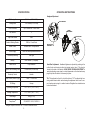
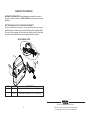
OPERATING INSTRUCTIONS
Headgear Adjustment
Head Size Adjustment: Headband tightness is adjusted by pushing in the
ratchet knob and turning to adjust to desired comfort level. This knob is
located at the back of the helmet. HEAD GEAR CROWN ADJUSTMENT is
made by adjusting crown strap for vertical placement on the head and snap-
ping the pin into the hole to lock securely in place.
Tilt: Tilt is adjusted on the left side of the helmet. TILT is adjusted by loos-
ening outside tension knob and releasing the adjustment lever from its cur-
rent location and moving it to another location. Retighten the outside tension
knob when finished.
4
SPECIFICATIONS
3
CROWN
AD
JUSTMENT
T
ILT ADJUSTMENT
RATCHET KNOB
PIN HOLES FOR
A
DJUSTMENT
LCD Viewing Area
Cartridge size
UV/IR Protection
Arc Sensors
Light State Shade
Variable Welding Shades
Shade Control
Power Supply
Low Battery Warning
Battery
Power On/Off
Light to Dark Switching Time
Sensitivity Control
Delay Control (Dark to Light)
TIG Rating
Operating Temperature
Storage Temperature
Total Weight
Compliance
(1)
97 x 44mm (3.82 x 1.73in)
110 x 90mm (4.33 x 3.54in)
Up to Shade DIN 16 at all times
2
DIN 4
DIN 9 to 13 and Grind
External knob - full adjustment
Solar cells with replaceable batteries
Red Light
AAA Alkaline (2 required)
Fully automatic
0.00004 sec (1/25,000 sec)
Variable
.1min. ~ 1.0 sec. max.
5 amps
14°F ~ 131°F (-10°C ~ 55°C)
-4°F ~ 158°F (-20°C ~ 70°C)
483g (17 Oz.)
CE,ANSI Z87.1-2003, CSA Z94.3
(1)
Headgear compliance with ANSI Z87.1 is without sweatband installed.

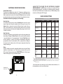
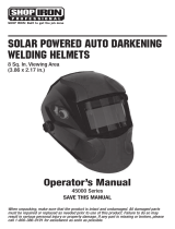
CARTRIDGE OPERATION/FEATURES
Variable Shade Control
The shade can be adjusted from shade 9 to 13 based upon welding process or
application (refer to Shade selection chart on page 6). The variable shade control
knob is mounted on the exterior of the helmet shell. Grind mode can be selected
by rotating the shade control knob counterclockwise till an audible click is heard.
Grind mode is intended for grinding only not for welding.
Sensitivity Knob
You can adjust the light sensor by turning the Sensitivity knob to the left or right as
shown in figure below. Generally, turning the knob all the way to the right, or the
highest setting, is selected for normal use. When the helmet is used in the pres-
ence of excess ambient light or with another welding machine close by, improved
helmet performance can be obtained with a lower setting turning the knob to the left
to reduce the sensitivity.
Delay Time Knob
This control is designed to protect the welder’s eyes from the strong residual rays
after welding. Changing the Delay Time knob will vary dark to light time between
.1 second (minimum) to 1.0 second (maximum). Turning the Delay Time knob to
the left is maximum (1.0 second). This setting is recommended for high amper-
age applications where the weld puddle is still very bright after the welding arc
has ceased and for situations where the filter may be temporarily blocked from
seeing the welding arc.
Power
This ADF cartridge is powered by replaceable batteries and solar power. Battery
installation is required prior to use. The batteries are located at the top of the
ADF cartridge. Replace batteries when LOW BATTERY light is lit. See the speci-
fication chart on page 3 for type of batteries required.
Variable shade
control Knob
5
ALWAYS TEST TO BE SURE THE ADF CARTRIDGE IS CHARGED
BEFORE WELDING. The TEST button is for the user to verify the ADF car-
tridgeis darkening properly. If cartridge is not darkening properly, replacebat-
teries with fresh batteries and test again before use. While welding, thearc
and solar cell will keep the ADF charged.
SHADE GUIDE SETTINGS
If your helmet does not include any one of the shades referenced above, it is
recommended you use the next darker shade.
6
L
H
T
I
S
I
V
N
E
S
I
T
Y
L
S
L
E
D
A
Y
TEST
LOW
BATTERY
S27978- 94
TMZ87W 4/9-13
CAN/CSA Z94.3 /
GUIDE FOR SHADE NUMBERS
O
PERATION ELECTRODE SIZE ARC MINIMUM SUGGESTED
(
1
)
1
/32 in. (mm) CURRENT (A) PROTECTIVE SHADE NO.
SHADE (COMFORT)
Shielded metal arc Less than 3 (2.5) Less than 60 7 –
welding 3-5 (2.5–4) 60-160 8 10
5-8 (4–6.4) 160-250 10 12
More than 8 (6.4) 250-550 11 14
Gas metal arc Less than 60 7 –
welding and flux 60-160 10 11
cored arc welding 160-250 10 12
250-500 10 14
Gas tungsten arc Less than 50 8 10
welding 50-150 8 12
150-500 10 14
Air carbon (Light) Less than 500 10 12
Arc cutting (Heavy) 500-1000 11 14
Plasma arc welding Less than 20 6 6 to 8
20-100 8 10
100-400 10 12
400-800 11 14
Plasma arc cutting (Light
)
(2)
(2)
(2)
Less than 300 8 9
(Medium) 300-400 9 12
(Heavy) 400-800 10 14
Tor c h b r a z in g – – 3 or 4
Tor c h s o l d er i n g – – 2
Carbon arc welding – – 14
PLATE THICKNESS
in. mm
Gas welding
Light Under 1/8 Under 3.2 4 or 5
Medium 1/8 to 1/2 3.2 to 12.7 5 or 6
Heavy Over 1/2 Over 12.7 6 or 8
Oxygen cutting
Light Under 1 Under 25 3 or 4
Medium 1 to 6 25 to 150 4 or 5
Heavy Over 6 Over 150 5 or 6
(1)
As
a
rule
of thumb, start with a shade that is too dark, then go to a lighter shade which gives sufficient view of the weld zone without going
below the
minimum. In oxyfuel gas welding or cutting where the torch produces a high yellow light, it is desirable to use a filter lens that absorbs
the
yellow or
sodium line the visible light of the (spectrum) operation
(2)
These values apply where the actual arc is clearly seen. Experience has shown that lighter filters may be used when the arc is hidden by the
workpiece.
.
Data from ANSI Z49.1-2005

SOLUTION
Clean or replace front
cover lens.
Clean the Auto-Darkening
cartridge with soapy water
solution and soft cloth.
Adjust sensitivity to required level.
Clean or replace front
cover lens.
Check for cracked or pit-
ted front cover lens and
replace as required.
Make sure you are not
blocking the sensors or
solar panels with your
arm or other obstacle
while welding. Adjust your
position so that the sen-
sors can see the weld arc.
Adjust sensitivity to required level.
Adjust to required level.
Replace front cover lens
as needed.
POSSIBLE CAUSE
Front cover lens dirty.
Cartridge dirty.
Sensitivity is set too low.
Front cover lens dirty.
Front cover lens is dam-
aged.
Sensors are blocked or
Solar panel is blocked.
Sensitivity set too high.
Delay set to high.
Missing, damaged,
broken, cracked or
distorted front cover
lens
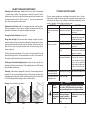
HELMET CARE AND MAINTENANCE
Replacing Front Cover Lens: Replace the front cover lens if it is damaged
– cracked, soiled or pitted. Place your finger or thumb into recess (C) at the
bottom edge of the cover lens and flex the lens upwards until it releases from
the edges marked A and B. (Refer to figure 1). Use only the replacement
front cover lenses specified in this manual.
Replace the Inside Cover Lens: if it is damaged (cracked, soiled or pitted).
Place your fingernail in recess above cartridge view window and flex lens
upwards until it releases from edges of cartridge view window.
Change the Shade Cartridge (See figure 2)
Fitting New Cartridge: Take the new shade cartridge and pass the poten-
tiometer cable under the wire loop before placing the cartridge into its retain-
ing frame inside the helmet. Hinge down the wire loop and ensure the front
edge of the loop (D) is properly retained under the retaining lugs (E) as
shown in (figure 3).
Position the shade potentiometer to the inside of the helmet with the shaft
protruding through the hole. Secure potentiometer to shell. On the outside of
the helmet, push the shade control knob onto the shaft.
Installing an Aftermarket Magnifying Lens: Unclip the wire loop (D) from
retaining lugs (E) and move hinge up. Place magnifing lens over ADF viewing
area and retain with wire loop.
Cleaning: Clean helmet by wiping with a soft cloth. Clean cartridge surfaces
regularly. Do not use strong cleaning solutions. Clean sensors and solar cells
with soapy water solution and a clean cloth and wipe dry with a lint-free cloth.
Do NOT submerge shade cartridge in water or other solution.
Storage: Store in a clean, dry location.
7
TROUBLE SHOOTING GUIDE
Test your shade cartridge prior to welding by directing the front of the car-
tridge toward a bright source of light, then using your fingers rapidly cover
and uncover the sensors. The cartridge should darken momentarily as the
sensor is exposed. A torch striker can also be used.
8
Figure 1
Figure 2 Figure 3
PROBLEM
Difficult to see through
filter.
Filter does not darken
when arc is struck.
Filter darkening with-
out arc being struck.
Filter remains dark after
completing a weld.
ADF is
cracked.
Weld spatter
is damaging
the filter.
WARNING
Cease (STOP) using this product if this prob-
lem exists. UV/IR protection may be compro-
mised resulting in burns to the eyes and skin.

WARRANTY INFORMATION
WARRANTY INFORMATION: These helmets are warranted for a period of
two years. Please contact us at 1 (866) 236-0044 for any service or warranty
questions.
SPATTER DAMAGE IS NOT COVERED BY WARRANTY:
Do not use this product without the correct protective clear cover lenses
installed properly on both sides of the Auto-Darkening Filter cartridge (ADF).
The cover lenses supplied with this helmet are properly sized to work with
this product and substitutions from other suppliers should be avoided.
REPLACEMENT PARTS
9
1
1
2
HELMET
SHELL
ITEM
1
2
PART NO.
KH778
KP2851-1
DESCRIPTION
INSIDE AND OUTSIDE COVER LENSES (2 EACH)
HEADGEAR ASSEMBLY WITH SWEATBAND
• Sales and Service through Subsidiaries and Distributors Worldwide •
2345 Murphy Blvd. Gainesville, GA 30504 TEL: 866-236-0044
• World's Leader in Welding and Cutting Products •
-
 1
1
-
 2
2
-
 3
3
-
 4
4
-
 5
5
-
 6
6


Lincoln Electric K4071-1 User manual
- Category
- Bicycle accessories
- Type
- User manual
- This manual is also suitable for
Ask a question and I''ll find the answer in the document
Finding information in a document is now easier with AI
Related papers
-
Century Darkening Helmet Operating instructions
-
Lincoln Electric K3057-1 Installation guide
-
Lincoln Electric VIKING 700G Operating instructions
-
-
-
-
Lincoln Electric VIKING 1740 Operating instructions
-
-
-
Other documents
-
-
 Autojack WH100W Owner's manual
-
 ATD Tools ATD-3721 User manual
-
Performax AntFi X60-2 User manual
-
 Antra Digital Diamond Series User manual
-
ESAB Auto-Darkening Welding Helmets User manual
-
METAL MAN ATEC8735SGC User manual
-
Harbor Freight Tools Variable Auto Darkening Welding Helmet with Metal Head Design User manual
-
ESAB A50 User manual
-
 Shop Iron 8820078 Owner's manual


