
—
ABB SOLAR INVERTERS
PVS-100/120 medium voltage compact skid
Hardware manual


Table of contents
1 Safety instructions
9Contents of this chapter ..........................................................................
9Use of warnings ...................................................................................
10Allowed usage .....................................................................................
10Safe installation, start-up and maintenance ..................................................
10General safety instructions ...................................................................
11MVCS working area safety ...................................................................
11Personal protective equipment (PPE) ..................................................
11Safety instructions for MV switchgear and MV transformer area ...................
12Safety instructions for the auxiliary services board ...................................
13Safe operation .....................................................................................
2 Introduction to this manual
15Contents of this chapter ..........................................................................
15Applicability ........................................................................................
15Target audience ...................................................................................
15Related documents ...............................................................................
16Terms and abbreviations .........................................................................
3 Hardware description
17Contents of this chapter ..........................................................................
17Product overview ..................................................................................
17External dimensions ..............................................................................
18Layout drawing ....................................................................................
18Working areas and main components .........................................................
19Main components .............................................................................
20AC cabinet components ......................................................................
20Inverter inputs ..................................................................................
20Auxiliary service board .......................................................................
22MV switchgear .................................................................................
22MV switchgear circuit ......................................................................
23MV transformer ................................................................................
24String inverter ..................................................................................
24Main circuit diagram ..............................................................................
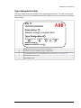
25Type designation label ...........................................................................
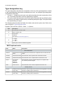
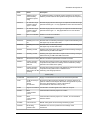
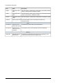
26Type designation key .............................................................................
26MVCS optional codes .........................................................................
4 Storing, lifting and transporting
29Contents of this chapter ..........................................................................
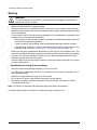
30Storing ..............................................................................................
30Conditions for using desiccant bags ........................................................
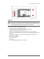
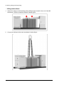
31Lifting ...............................................................................................
31Tools used for lifting ...........................................................................
32Lifting instructions .............................................................................
Table of contents 5

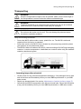
33Transporting .......................................................................................
33Incoming inspection at arrival ...............................................................
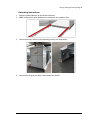
34Unloading ..........................................................................................
34Tools used for unloading .....................................................................
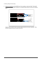
35Unloading instructions ........................................................................
5 Mechanical installation
37Contents of this chapter ..........................................................................
37Safety ...............................................................................................
37Tools ................................................................................................
37Foundation guidelines ............................................................................
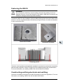
38Placing the MVCS on the foundation ..........................................................
39Fastening the MVCS .............................................................................
39Constructing earthing electrode and earthing ................................................
40Filling the pit and finalizing the surroundings .................................................
6 Electrical installation
41Contents of this chapter ..........................................................................
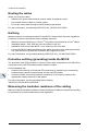
42Routing the cables ................................................................................
42Earthing ............................................................................................
42Protective earthing (grounding) inside the MVCS ............................................
42Measuring the insulation resistance of the cabling ..........................................
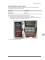
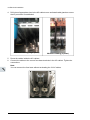
43Connecting the inverter inputs ..................................................................
45Connecting the communication and auxiliary cabling (Optional) ..........................
45Connecting the power grid cabling to the MV switchgear ...................................
7 Finalizing the installation
47Contents of this chapter ..........................................................................
47Finalizing the installation .........................................................................
48Landscaping the station ..........................................................................
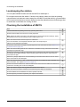
48Checking the installation of MVCS .............................................................
8 Start-up and operation
49Contents of this chapter ..........................................................................
49Tools needed ......................................................................................
49Prerequisite ........................................................................................
50Start-up procedure ................................................................................
9 Maintenance
53Contents of this chapter ..........................................................................
53Tools list ............................................................................................
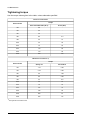
54Tightening torque .................................................................................
55Maintenance intervals ............................................................................
55Maintenance activities ........................................................................
56Maintenance intervals ........................................................................
56Cleaning procedure ...............................................................................
57Maintenance of painted surfaces ...............................................................
57Repainting the scratched areas .............................................................
57Tools and materials ........................................................................
58Painting the damaged surface (no visible rust) .......................................
6 Table of contents

58Painting the damaged surface (visible rust) ...........................................
58Maintenance of Zinc coated surfaces ......................................................
58Maintenance of grounding bars and points ...................................................
58Tools .............................................................................................
59Procedure ......................................................................................
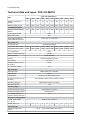
10 Technical data
61Contents of this chapter ..........................................................................
62Technical data and types: PVS-100 MVCS ..................................................
64Technical data and types: PVS-120 MVCS ...................................................
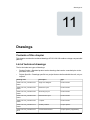
11 Drawings
67Contents of this chapter ..........................................................................
67List of technical drawings ........................................................................
Further information
Table of contents 7

8

Safety instructions
Contents of this chapter
This chapter presents the use of warnings in the manual and gives instructions for safe
installation, start-up, use and maintenance of the PVS-100/120 medium voltage compact
skid (MVCS).
Use of warnings
Warnings caution you about conditions which can result in serious injury or death and/or
damage to the equipment, and advise on how to avoid the danger. The following warning
symbols are used in this manual:
WARNING!
Electricity warning warns of hazards from electricity which can cause physical
injury and/or damage to the equipment.
WARNING!
General warning warns about conditions, other than those caused by electricity
which can result in physical injury and/or damage to the equipment.
WARNING!
General warning warns about weather conditions, prohibited maintenance
operations during a typhoon, thunderstorm, snow, rain and electrical storm.
Maintenance in such conditions can result in physical injury and/or damage to the
equipment.
1
Safety instructions 9

WARNING!
General warning warns about maintenance work on the roof which should always
be done from the outer perimeter, considering the local safety regulations.
Allowed usage
• The PVS-100/120 medium voltage compact skid (MVCS) is designed to transform AC
current from a group of inverters and finally feed to a medium voltage grid. Use the
MVCS only at its permissible input/output ratings and ambient conditions. Make sure
this compliance is satisfied before commissioning.
• The operation and maintenance of the MVCS must be carried out by certified technicians
that fulfill all local skill set and safety requirements. Any unqualified personnel must
maintain a safe distance from the MVCS. All activities must be in accordance with the
criteria described in the ABB technical documents and local regulations.
• Make changes to the MVCS only with the direct authorization of ABB. Any alterations
done outside ABB approval will invalid the warranty for the product. ABB is not liable
for any damages caused by these changes.
• The MVCS is a non-walk-in type station, designed to be operated from the outside.
Make sure the side doors are closed at all times during operation and that no personnel
is inside or in the near vicinity of the MVCS.
Safe installation, start-up and maintenance
This section contains the safety instructions which you must follow when installing,
commissioning and maintaining the MVCS. If ignored, physical injury or death may follow,
or damage may occur to the equipment.
• Only authorized electricians are allowed to install, start-up and maintain the MVCS.
Working methods, tools, components etc. must follow the IEC regulations.
• Obey all local safety regulations concerning electrical stations.
• The MVCS should be energized and de-energized only by an authorized person who
has the task-specific instructions for the operation of an MV substation and permission
from the on-site foreperson in charge of electrical work.
• If other people must be in the vicinity while the door is open, warn them, and if required,
provide supervision and guidance.
■ General safety instructions
WARNING!
Before you perform any work in the MVCS, obey the following safety precautions.
1. Clearly identify the work location.
2. Read the safety instructions of the work area and the component you are working on.
See the subsections below and the component-specific manuals.
3. Disconnect and secure against reconnection.
4. Disconnect all possible power supplies (external, auxiliary and inverters) and open all
base fuse switches. Lock the disconnectors in the open position and attach a warning
notice to them. After disconnecting power to the inverters, always wait until the stored
energy of the inverters is discharged. See also, inverters manual.
5. Use protection against any live parts.
10 Safety instructions
3

6. Take special precautions when you work close to exposed conductors.
7. Measure to ensure that there is no voltage connected.
8. Carry out earthing (grounding) and short circuiting.
9. Issue a permit to work.
■ MVCS working area safety
The MVCS has three working areas:
• AC Cabinet Area
• MV Transformer Area
• MV Switchgear Area
Each work area has separate safety instructions.
Personal protective equipment (PPE)
• Perform any operation on the equipment with suitable work clothes and instruments.
• When choosing a personnel protective equipment, consider environmental conditions
such as humidity, noise, etc. and local regulations.
• Make sure the work clothes and accessories are not prone to generate electrostatic
charges, fires or any other condition that compromises personnel safety.
• The minimum required safety equipment is as follows:
• Safety shoes
• Safety gloves
• Safety glasses
• Head protection
• Hearing protection
• Work clothes
Safety instructions for MV switchgear and MV transformer area
WARNING!
Perform the below instructions before you start working inside the MV switchgear
and/or MV transformer area. Ignoring the instructions can cause physical injury or
death, or damage to the equipment.
1. Identify the MV switchgear and read its safety instructions.
2. Check the operation of the capacitive voltage indicators in all MV switchgear bays (all
phase LEDs are switched on when a voltage is connected).
3. Disconnect the MV switchgear from all possible power supplies (external, auxiliary, and
inverters as well as any parallel connection stations), and secure by locking and tagging.
a. Stop the string inverters outside the MVCS. Open the DC disconnecting switches
in each inverter unit and add warning notices. If applicable, open the AC
disconnecting switches in each inverter unit, lock and add warning notices.
b. Open all fuse base switches of the inverter inputs, lock and add warning notices.
c. Open all auxiliary breakers, switches and fuses in the auxiliary service board, lock
and add warning notices.
d. Turn the vacuum circuit breaker of the MV switchgear to open position. Lock and
add warning notice.
Safety instructions 11

e. Turn the disconnecting switch of the MV transformer side of the MV switchgear to
open position. Lock and add a warning notice.
f. Disconnect the MV switchgear from the MV network (all possible external power
supplies, grid and parallel stations). See the User's manual of the MV switchgear.
Lock and add warning notices.
4. Check that all shrouds/screens are in place.
5. Check that you are not near to any live parts while working. All live circuits must be
protected with shrouds/screens.
6. Make sure that the MV switchgear is dead.
• Check the status of voltage indicators in all MV switchgear bays. Note that all phase
LEDs which were switched on AC cabinet at step 3 are now switched off).
7. Earth the MV switchgear and AC cabinet.
• Turn the earthing switches of the MV switchgear to “earthed” position, lock (remove
the MV switchgear Ronnis key of the V module) and add warning notices. If the
station is connected to parallel stations, make sure that you also turn the appropriate
earthing switches of the parallel stations to “earthed” position.
• Temporarily, ground the MV switchgear terminals at all possible external power
supplies (grid and parallel stations). See the User's manual of the MV switchgear.
Lock and add warning notices.
• Ground the inverter AC sides with appropriate temporary grounding set.
8. Check that the MV transformer is dead (high voltage terminals, low voltage terminals,
any auxiliary power, and instrumentation). Use an appropriate high voltage tester only
for the high voltage side, and a voltage detector with suitable testing heads for the low
voltage side.
9. Issue a work permit.
Safety instructions for the auxiliary services board
1. Open the main circuit breaker or main switch of the auxiliary service transformer, and
secure by locking and tagging.
2. Open the secondary circuit breaker of the auxiliary service transformer, and secure by
locking and tagging.
3. Open all switches, breakers and connectors of the auxiliary service board, and secure
by locking and tagging.
4. Make sure you are not near to any live parts while working. Disconnect the live circuits
or protect them with shrouds/screens.
5. Check the status of the voltage indicators in the auxiliary service board.
6. Check that the auxiliary service board is dead.
7. Issue a work permit.
12 Safety instructions
3

Safe operation
This section contains the safety instructions which you must follow when operating the
MVCS. If ignored, physical injury or death, or damage may occur.
WARNING!
Obey these instructions to prevent injury, death, or damage to the equipment
WARNING!
Keep all doors locked while the MVCS is operating. Allow access to only authorized
personnel.
1. Keep all doors of the MVCS closed during operation. Give the keys only to authorized
personnel.
2. Before you start a group of inverters, check the connections of each inverter input, and
the recommendations in the specific inverter manual.
3. Do not open the AC base fuse switches when the MVCS is operating.
4. Before you adjust the group of inverters and set them into service, make sure that all
of them are suitable for operation.
5. Do not use the inverters in a manner not specified in the manual.
Note:
• Spend as little time as possible near the inverters or the MVCS.
• Use a personal computer with a communication cable of sufficient length when you
monitor or adjust inverter parameters during operation.
Safety instructions 13

14

Introduction to this manual
Contents of this chapter
This chapter provides information about the manual such as applicability, target audience
and contents. It also lists the related documents.
Applicability
This manual is applicable to PVS-100/120 medium voltage compact skid (MVCS).
Target audience
This manual is intended for persons who transport, store, plan the installation, install,
commission and maintain the MVCS.
Read this manual before working on the MVCS. You are expected to know the fundamentals
of electricity, wiring, electrical components and electrical schematic symbols.
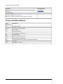
Related documents
Code (English)Document
Inverter manuals and guides
9AKK107045A7607PVS-100/120-TL Product Manual
9AKK107492A2231PVS-100/120-TL Quick Installation Guide
Option manuals and guides
9AKK107046A0405DRMO-INTERFACE- Quick Installation Guide
9AKK10103A3456String inverter- Product Manual Appendix
Other manuals and guides
1YVA000024SafeRing/SafePlus 24 kV SF6 insulated Ring Main Unit and Compact
Switchgear
2
Introduction to this manual 15

Code (English)Document
1YVA000026SafeRing/SafePlus 36 kV SF6 insulated Ring Main Unit and Compact
Switchgear
List of drawings
-
See list in chapter Drawings (page 67).
Note: The drawings are delivered with the unit only on request.
Terms and abbreviations
DescriptionTerm/
Abbreviation
Alternating currentAC
Construction of MV switchgearCV/CCV
Direct currentDC
High cube containerHC
Low voltage (50...1000 V AC)LV
Medium voltageMV
Medium voltage compact skidMVCS
Personal protective equipmentPPE
Sulfur hexafluoride (this gas type is used in MV switchgear).SF6
SwitchgearSWG
Total harmonic distortionTHD
16 Introduction to this manual

Hardware description
Contents of this chapter
This chapter provides an overview of the PVS-100/120 medium voltage compact skid
(MVCS). It also includes layout, type designation label and type designation information.
Product overview
The PVS-100/120 medium voltage compact skid connects a group of inverters to a medium
voltage power grid. This solution is constructed around a skid house that contains:
• MV transformer—transforms low voltage from inverters to medium voltage for the
power grid.
• Auxiliary service transformer—supplies power to the AC cabinet and auxiliary
components of the MVCS.
• MV switchgear—connects to the power grid. It is also the main protecting, switching,
breaking and disconnecting equipment of the medium-voltage side of the solar power
plant.
• AC cabinet—contains all parallel connections to the inverter inputs and the auxiliary
service boards (required for the autonomous function of the MVCS). Note that the AC
cabinet also includes an additional space for customer use (e.g. communication board,
etc.).
External dimensions
The MVCS is constructed over a skid suitable for transportation inside a 20 HC container
with,
• External dimension (length, width, height) = 5700 x 2150 x 2500 mm
• Total weight = 11 ton.
3
Hardware description 17

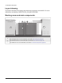
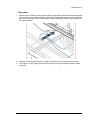
Layout drawing
This section describes the working areas and main components of the MVCS. For more
information, see drawing, 3AES-PVS-100_120_MVCS-30-DW01.
Working areas and main components
40
थापना साइट की जांच करना
R0...R2
:
•
•
A
B
C
1
2
MV switchgear area. For more information, see section MV switchgear (page 22).
A
MV transformer area. For more information, see section MV transformer (page 23).
B
AC cabinet area. For more information, see section AC cabinet components (page 20).
C
18 Hardware description

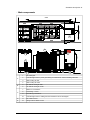
■ Main components
39
4
यांिक थापना
•
Aux. Breakers and others
1U
Ø200
152
5700
2500
2150
7
8
5
6
6
4
3
2
1
4
3
3
4
9
9
10
12
11
MV switchgear1
A
Lead-through holes for power grid cabling and terminal for external earthing electrode2
SWG cooling air inlet3
SWG cooling air outlet4
AC cabinet cooling air inlet5
B
AC cabinet cooling air outlet6
Busbar LV connections7
C
LV bushing / LV box8
HV bushing connections9
Lead-through holes for cabling from MV transformer to MV switchgear10
MV cables access11D
String inverter cables access12E
Hardware description 19

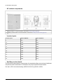
■ AC cabinet components
Inverter inputs. For more information, see section Inverter inputs (page 20).
A
Auxiliary service board. For more information, see section Auxiliary service board (page 20).
B
■ Inverter inputs
PVS-120-MVCS-...PVS-100-MVCS-...Inverter inputs
9608008
1200100010
1440120012
1680140014
1920160016
2160180018
2400200020
2640220022
2880240024
3120260026
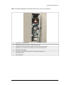
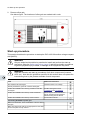
■ Auxiliary service board
The figure below describes the components of a standard auxiliary service board. Additional
components and customization is included in the project specific documentation.
See also, UPS connection drawing 3AES-PVS-100/120_MVCS-14-SP01.
20 Hardware description
Page is loading ...
Page is loading ...
Page is loading ...
Page is loading ...
Page is loading ...
Page is loading ...
Page is loading ...
Page is loading ...
Page is loading ...
Page is loading ...
Page is loading ...
Page is loading ...
Page is loading ...
Page is loading ...
Page is loading ...
Page is loading ...
Page is loading ...
Page is loading ...
Page is loading ...
Page is loading ...
Page is loading ...
Page is loading ...
Page is loading ...
Page is loading ...
Page is loading ...
Page is loading ...
Page is loading ...
Page is loading ...
Page is loading ...
Page is loading ...
Page is loading ...
Page is loading ...
Page is loading ...
Page is loading ...
Page is loading ...
Page is loading ...
Page is loading ...
Page is loading ...
Page is loading ...
Page is loading ...
Page is loading ...
Page is loading ...
Page is loading ...
Page is loading ...
Page is loading ...
Page is loading ...
Page is loading ...
Page is loading ...
Page is loading ...
Page is loading ...
-
 1
1
-
 2
2
-
 3
3
-
 4
4
-
 5
5
-
 6
6
-
 7
7
-
 8
8
-
 9
9
-
 10
10
-
 11
11
-
 12
12
-
 13
13
-
 14
14
-
 15
15
-
 16
16
-
 17
17
-
 18
18
-
 19
19
-
 20
20
-
 21
21
-
 22
22
-
 23
23
-
 24
24
-
 25
25
-
 26
26
-
 27
27
-
 28
28
-
 29
29
-
 30
30
-
 31
31
-
 32
32
-
 33
33
-
 34
34
-
 35
35
-
 36
36
-
 37
37
-
 38
38
-
 39
39
-
 40
40
-
 41
41
-
 42
42
-
 43
43
-
 44
44
-
 45
45
-
 46
46
-
 47
47
-
 48
48
-
 49
49
-
 50
50
-
 51
51
-
 52
52
-
 53
53
-
 54
54
-
 55
55
-
 56
56
-
 57
57
-
 58
58
-
 59
59
-
 60
60
-
 61
61
-
 62
62
-
 63
63
-
 64
64
-
 65
65
-
 66
66
-
 67
67
-
 68
68
-
 69
69
-
 70
70


Ask a question and I''ll find the answer in the document
Finding information in a document is now easier with AI
Related papers
-
ABB PVS-175-TL Series Quick Installation Manual
-
ABB PVS-175-TL-US User manual
-
-
-
-
-
-
-
-
Other documents
-
HQ W8-65050N Datasheet
-
Hager VME01SPD Protection Devices Surge Protection Kit User manual
-
MSI DBLBWL6040-3120 Installation guide
-
Marathon MVC 300 Owner's manual
-
Quantum Scalar 24 Installation guide
-
Sealite SL-RMU Quick start guide
-
Peavey PVs 12 User manual
-
Peavey PVS-18-SUB User manual
-
Metro DataVac TT-2X4 User manual
-
Wilo Control SC-L Installation And Operating Instructions Manual