MICRO-EPSILON reflectCONTROL Sensor User manual
- Category
- Measuring & layout tools
- Type
- User manual

MICRO-EPSILON MESSTECHNIK GmbH & Co. KG
Koenigbacher Str.15 · 94496 Ortenburg / Germany
Phone +49 8542 168 0 · Fax +49 8542 168 90
[email protected] · www.micro-epsilon.com
Your local contact: www.micro-epsilon.com/contact/worldwide/
Operating Instructions
reflectCONTROL Sensor
RCS130-160

MICRO-EPSILON
MESSTECHNIK
GmbH & Co. KG
Koenigbacher Str.15
94496 Ortenburg / Germany
Phone +49 (0) 85 42/1 68-0
Fax +49 (0) 8542/168-90
www.micro-epsilon.com
reflectCONTROL Sensor

reflectCONTROL Sensor
Contents
1. Safety .......................................................................................................................................... 5
1.1 Symbols Used .................................................................................................................................. 5
1.2 Warnings ........................................................................................................................................... 5
1.3 Notes on CE Marking ....................................................................................................................... 5
1.4 Intended Use .................................................................................................................................... 6
1.5 Proper Environment ......................................................................................................................... 6
1.6 Software Security.............................................................................................................................. 6
2. Functional Principle, Technical Data ......................................................................................... 7
2.1 Measuring Principle .......................................................................................................................... 7
2.2 Structure ........................................................................................................................................... 7
2.3 Requirements for the Target ............................................................................................................. 7
2.4 Technical Data .................................................................................................................................. 8
3. Delivery ....................................................................................................................................... 9
3.1 Unpacking/Included in Delivery ....................................................................................................... 9
3.2 Storage ............................................................................................................................................. 9
4. Installation and Assembly ........................................................................................................ 10
4.1 Precautions ..................................................................................................................................... 10
4.2 RCS130-160 Dimensions, Measuring Window .............................................................................. 10
4.3 Electrical Connections, Interfaces .................................................................................................. 11
4.3.1 Interfaces .......................................................................................................................................... 11
4.3.2 Connection Options ......................................................................................................................... 11
4.3.3 Supply Voltage ................................................................................................................................ 12
5. Operation .................................................................................................................................. 13
5.1 General ........................................................................................................................................... 13
5.2 Process to Turn On and Turn Off .................................................................................................... 13
5.2.1 Turning On ....................................................................................................................................... 13
5.2.2 Turning Off ........................................................................................................................................ 13
5.3 Positioning Target ........................................................................................................................... 14
5.4 Shading .......................................................................................................................................... 14
5.5 Measurement Procedure ................................................................................................................ 15
6. Liability for Material Defects .................................................................................................... 16
7. Service, Repair ......................................................................................................................... 16
8. Decommissioning, Disposal .................................................................................................... 16
Appendix
A 1 Optional Accessories ............................................................................................................... 17
A 2 GenICam reflectCONTROL Parameters .................................................................................. 18

reflectCONTROL Sensor

Page 5
Safety
reflectCONTROL Sensor
1. Safety
System operation assumes knowledge of the operating instructions.
1.1 Symbols Used
The following symbols are used in these operating instructions:
CAUTION
Indicates a hazardous situation which, if not avoided, may result in
minor or moderate injury.
NOTICE
Indicates a situation that may result in property damage if not
avoided.
Indicates a user action.
i
Indicates a tip for users.
Measurement
Indicates hardware or a software button/menu.
1.2 Warnings
Connect the power supply and the display/output device according to the safety regulati-
ons for electrical equipment.
> Risk of injury
> Damage to or destruction of the sensor and/or the controller
Avoid impacts and shocks to the system.
> Damage to or destruction of the system
Protect the cables against damage.
> Failure of the measuring device
1.3 Notes on CE Marking
The following apply to the reflectCONTROL Sensor RCS130-160 series:
- EU Directive 2014/30/EU
- EU Directive 2011/65/EU
Products which carry the CE mark satisfy the requirements of the EU directives cited and
the relevant applicable harmonized European standards (EN). The measuring system is
designed for use in industrial environments.
The EU Declaration of Conformity and the technical documentation are available to the
responsible authorities according to the EU Directives.
CAUTION
NOTICE

Page 6
Safety
reflectCONTROL Sensor
1.4 Intended Use
The measuring system is designed for use in an industrial environment.
It is used for non-contacting surface inspection of highly reflecting materials, quality mo-
nitoring and dimensional inspection.
The measuring system must only be operated within the limits specified in the technical
data, see 2.4.
The system must be used in such a way that no persons are endangered or machines
and other material goods are damaged in the event of malfunction or total failure of the
system.
Take additional precautions for safety and damage prevention in case of safety-related
applications.
1.5 Proper Environment
- Area between camera and target must not be soiled (for example water, abrasion, dust
etc.).
- Temperature range:
Operation: +10 ... +40 °C (+50 ... +104 °F), general
Operation: +22 °C ±2 °C (+71.6 °F ±3.6 °F) for 3D measurements
Storage: -10 ... +60 °C (+14 ...+140 °F)
- Humidity: 10 % ... 80 %, (non-condensing)
- Ambient pressure: Atmospheric pressure
- Area between sensor and target must be free of water, abrasion,
dust etc.
1.6 Software Security
The following important information must be observed for all application software based
on reflectCONTROL. The modification of hardware or software components is essentially
not permitted. Exceptions must be approved of in writing by Micro-Epsilon Messtechnik
GmbH & Co. KG.
The automatic start of software components that do not originate from Micro-Epsilon
Messtechnik GmbH & Co. KG and which run in the background of the measurement pro-
cess is not permitted. During the use of virus scanners there may be limitations in system
availability.
The integration of systems from Micro-Epsilon Messtechnik GmbH & Co. KG into net-
works must only be performed by qualified personnel. In doing so, the system operator
is responsible for security on the network.
Micro-Epsilon Messtechnik GmbH & Co. KG shall accept no claims arising from non-
observance of these safety instructions.

Page 7
Functional Principle, Technical Data
reflectCONTROL Sensor
2. Functional Principle, Technical Data
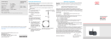
2.1 Measuring Principle
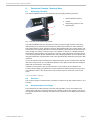
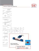
The reflectCONTROL Sensor automatically inspects highly reflecting surfaces.
1
2
3
1 reflectCONTROL Sensor
2
Holder
1
3
Supporting surface for the
target/object
1
Fig. 1 Full view of the measuring system
The reflectCONTROL Sensor operates according to the principle of phase measuring
deflectometry. The measurement technique is particularly suitable for defect detection
and measurement of even reflecting surfaces. With deflectometry, the surface itself is not
examined but its optically distorted or intensity weakening effect which shows itself in the
mirror image of a pattern. In the process, a sine pattern is shown on a display and then
the reflection of this pattern is recorded by a camera. A few images are recorded using a
CCD camera between phase displacements of the displayed pattern and curvatures and
intensity amplitudes over the entire surface are algorithmically determined using the data
obtained.
For the 3D measurement, simultaneous image acquisition by two cameras from different
directions is performed. The combined evaluation of the data of both cameras enables a
stable 3D reconstruction of the target.
Calibration is required for the 3D reconstruction. The positions of the cameras, the
screen and the imaging characteristics of the cameras are determined here using a spe-
cial calibration mirror. The 3D reconstruction provides a point cloud with X/Y/Z coordi-
nates.
1) Not included in delivery
2.2 Structure
The compact system contains all the necessary components for the measurement in one
housing.
2.3 Requirements for the Target
The prerequisite for deflectometry is that the striped pattern can be recorded by the
camera via the target. As flat and reflecting as possible surfaces are optimal. Convex cur-
ved targets (beams are scattered) may have to be examined from multiple measurement
positions.

Page 8
Functional Principle, Technical Data
reflectCONTROL Sensor
2.4 Technical Data
Model RCS130-160
Measurement area
Length x width (x * y)
1
in reference plane 170 mm x 160 mm
Acquisition of measurement data approx. 1.2 s … 6 s
Evaluation approx. 2 s … 8 s
Resolution x, y 100 µm
Planarity measurement error z
2
< 1 µm
Supply voltage 24V DC (must not exceed 26 V)
Power consumption < 50 W
Interfaces and connections
1 x GigE Vision (RJ45), 1 x Ethernet (RJ45),
power supply (3-pin Lemo connector)
Mounting mechanically reproducible adapter flange
Temperature range
Storage -10 ... +60 °C (+14 ...+140 °F)
Operation
2
0 °C … +40 °C (+32 °F ... +104 °F)
(for 3D measurements: max. fluctuation of ±2 °C
after referencing)
Humidity
2
10 % … 80 %, non-condensing
(for 3D measurements: max. fluctuation of ±2 %
after referencing)
Design
carbon housing with controlled fan, design
with integrated controller
Weight < 7 kg
1) Size specifications refer to the reference plane. Trapezoidal measuring field - the medium width is specified. Exact
dimensions, see Fig. 2.
2) Measured after referencing with a plane mirror (Ø 300 mm and a flatness of lambda/10) at a max. distance toleran-
ce of ±0.1 mm. After referencing, a maximum temperature fluctuation of ± 2 °C and change of humidity of ±2 % are
to be complied with.

Page 9
Delivery
reflectCONTROL Sensor
3. Delivery
3.1 Unpacking/Included in Delivery
1 Measuring system
1 24V supply cable, open ends
1 Operating instructions
Carefully remove the components of the measuring system from the packaging and
ensure that the goods are forwarded in such a way that no damage can occur.
Check the delivery for completeness and shipping damage immediately after unpa-
cking.
If there is damage or parts are missing, immediately contact the manufacturer or
supplier.
3.2 Storage
Temperature range (storage): -10 ... +60 °C (+14 ...+140 °F)
Humidity: 10 % ... 80 % (non-condensing)

Page 10
Installation and Assembly
reflectCONTROL Sensor
4. Installation and Assembly
4.1 Precautions
No sharp or heavy objects should be allowed to affect the cable sheath.
Avoid folding the cables. Check the plug-in connections for firm seating.
The measuring system is an optical system used to measure in the µm range.
i
Ensure careful handling during installation and operation.
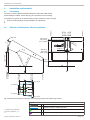
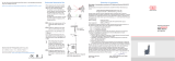
4.2 RCS130-160 Dimensions, Measuring Window
228 (8.98)
(200 / 7.87)
219 (8.62)
0
240.8 (9.48)
X
Z
163.2 (6.42)
218.2 (8.59)
3007154
Z
Y
( )
1
362 (14.25)
356 (14.01)
351.7 (13.85)
206 (8.11)
200 (7.87)
189.4 (7.46)
0
75.3
(2.96)
210 (8.27)
40 (1.57)
28 (1.10)
20 (.79)
20 (.79)
28 (1.10)
40 (1.57)
210 (8.27)
0
5 H8
+0.018
-0
( )
ø5 H8
+0.018
-0
ø5.5
(4x)
0
61.3 (2.41)
61.3 (2.41)
0
90.7 (3.57)
99.3 (3.91)
71 (2.79)
74.8 (2.94)
0
104.7 (4.12)
104.7 (4.12)
160.7 (6.33)
1)
42
(1.65)
Fig. 2 Dimensional drawing of RCS130-160 measuring system with measuring window
Legend
Position of target/object
Outer boundary of measuring field
Piercing points of both cameras’ main beams
Zero point of the measuring field’s coordinate system
1) Optionally available
mounting adapter, see
A 1

Page 11
Installation and Assembly
reflectCONTROL Sensor
65 (2.56)
0
1 (.04)
24.5 (.96)
65 (2.56)
38.5 (1.52)
31 (1.22)
19.25 (.76)
15.75 (.62)
0
19.25 (.76)
31 (1.22)
38.5 (1.52)
210 (8.27)
92 (3.62)
210 (8.27)
123 (4.84)
61 (2.40)
0
0.6 (.02)
33.34 (1.31)
33.34 (1.31)
M5x0.8 - 6H
(6x)
( )
ø20 H7
+0.021
-0
( )
5 H7
(3x)
+0.012
-0
ø90
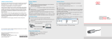
Fig. 3 Dimensional drawing of mounting bores
4.3 Electrical Connections, Interfaces
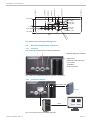
4.3.1 Interfaces
The measuring system has the following interfaces:
1 2
1 Ethernet diagnosis interface
2 GigE Vision
Parameter setting and pro-
cess control
1000 Mbps,
RJ45 connection
Fig. 4 Rear view of RCS130-160 with interface connections
4.3.2 Connection Options
HDMI
RC Sensor 24V
PS 2020
Fig. 5 Connection plan for standard operation

Page 12
Installation and Assembly
reflectCONTROL Sensor
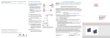
4.3.3 Supply Voltage
Nominal value: 24 V DC (22.8 ... 25.2 V, P < 60 W).
Only turn on the power supply after wiring has been completed.
Connect the inputs “1” and “2” at the sensor with a 24V power supply.
RC Sensor 24V
1
2
22,8 ...
25,2 VDC
Cable RC Sensor 24V Assignment
black (1) +24 V
black (2) Ground
yellow/green PE
Fig. 6 Supply voltage connection
Use the power supply only for measuring devices; do not use it at the same time for dri-
ves or similar sources of impulse interference. MICRO-EPSILON recommends using the
optionally available PS2020 power supply, for the sensor, see A 1.

Page 13
Operation
reflectCONTROL Sensor
5. Operation
5.1 General
The software is installed on the sensors at the factory. The user is not required to perform
any installation. The sensor is accessed via GenICam/GigE Vision from Version 2.1.
The package includes a download link to the client software from Micro-Epsilon. This
package consists of the 3D-View software and an SDK with corresponding sample
programs.
3D-View can be installed on Windows 7/8/10 (64-bit) computers and enables
- the setting of system parameters,
- the execution of measurements and
- the visualization of measurement results.
The measurement data generated can be exported in different standard formats.
5.2 Process to Turn On and Turn Off
5.2.1 Turning On
The system starts when the supply voltage is applied. The controller in the sensor starts
the boot process.
The system will be operational after a startup time of approx. 60 sec.
It can then be connected to any compatible software via GigE Vision, e.g., 3D-View by
Micro-Epsilon.
5.2.2 Turning Off
Turn off the system as follows:
Disconnect the 24V power supply.

Page 14
Operation
reflectCONTROL Sensor
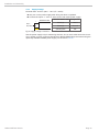
5.3 Positioning Target
The surface of the target must be in the depth of field range of the lenses both for the de-
fect detection as well as for the 3D reconstruction. The tolerances for the vertical positio-
ning are approx. 40 µm (-20 µm to +20 µm). The dimensions of the measuring fields that
the target must be located within can be found in the dimensional drawing, see Fig. 2.
228 (8.98)
(200 / 7.87)
219 (8.62)
0
240.8 (9.48)
X
Z
Target
+0.02
-
0.02
Fig. 7 Vertical tolerance field for the target surface
Position the measuring system so that it is level.
5.4 Shading
Lateral scattered light on the target can cause measurement inaccuracies.
i
Avoid scattered light, e.g. bright daylight, on the target.
Shade the measurement environment if required.

Page 15
Operation
reflectCONTROL Sensor
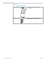
5.5 Measurement Procedure
Let the measurement equipment warm up for approx. 15 minutes, 120 minutes for high-
precision measurements, before you perform any measurement. This prevents measure-
ment inaccuracies.
The following table shows the most important steps of a measurement process:
Step 1 Positioning target Chap. 5.3
Step 2 Basic settings, e.g. camera, striped pattern
Step 3 Image acquisition
Step 4 2D Data processing 3D Data processing
Result images:
base intensity, amplitude,
curvature
3D point cloud
Step 5 Save results
Fig. 8 Measurement process steps, software blocks
Place the target in the object plane for the measurement. Then, the camera (exposure
time), the striped pattern and the number of images can be parametrized. Depending on
the selected number of images, the image acquisition takes approx. 1 ... 2 s. The result
images of the deflectometry are available after the data processing in 2D mode or 3D
mode. The expected processing time is 1… 60 s which particularly depends on the Bin-
ning, ReconstructionGridsize and Patterntype parameters.
Details about setting the parameters are available in the software description.
Please refer to the appendix, see A 2, for details about the parameters.

Page 16
Liability for Material Defects
reflectCONTROL Sensor
6. Liability for Material Defects
All components of the device have been checked and tested for functionality at the
factory.
However, if defects occur despite our careful quality control, MICRO-EPSILON or your
dealer must be notified immediately.
The liability for material defects is 12 months from delivery. Within this period, defective
parts, except for wearing parts, will be repaired or replaced free of charge, if the device is
returned to MICRO-EPSILON with shipping costs prepaid.
Any damage that is caused by improper handling, the use of force or by repairs or modi-
fications by third parties is not covered by the liability for material defects.
Repairs are carried out exclusively by MICRO-EPSILON.
Further claims can not be made. Claims arising from the purchase contract remain unaf-
fected.
In particular, MICRO-EPSILON shall not be liable for any consequential, special, indirect
or incidental damage.
In the interest of further development, Micro-Epsilon reserves the right to make design
changes without notification. For translations into other languages, the German version
shall prevail.
7. Service, Repair
For any defect on the system:
- If possible, save the current system
settings in a parameter set to reload them
into the system after the repair.
If the cause of a fault cannot be clearly
identified, please send the entire measuring
system to:
MICRO-EPSILON MESSTECHNIK
GmbH & Co. KG
Koenigbacher Str. 15
94496 Ortenburg / Germany
Tel. +49 (0) 8542 / 168-0
Fax +49 (0) 8542 / 168-90
www.micro-epsilon.com
8. Decommissioning, Disposal
Remove the electrical connection cables from the measuring system.
Incorrect disposal may cause harm to the environment.
Dispose of the device, its components and accessories, as well as the packaging
materials in compliance with the applicable country-specific waste treatment and
disposal regulations of the region of use.

Page 17
Anhang | Optional Accessories
reflectCONTROL Sensor
Appendix
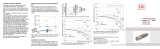
A 1 Optional Accessories
rC Sensor adapter Mounting adapter from AlMg4.5Mn0.7
item 3007154
PS2020 Power supply for DIN rail installation;
input 230 VAC, output 24 VDC/2.5 A

Page 18
Anhang | GenICam reflectCONTROL Parameters
reflectCONTROL Sensor
A 2 GenICam reflectCONTROL Parameters
Details about setting the parameters are available in the software description, see 3D View operating instructions.
Parameter Description
Observe the notes below if you operate the sensor with a third party library for GenICam/GigE Vision:
- The library must support GigE Vision 2.1. In particular, MultiPart mode must be supported.
- Three sources are available to set the parameters of the sensor, see the SourceSelector description below.
However, data are always transmitted using StreamChannel 0. Before starting data transmission with the Ac-
quisitionStart command, the entry Source0 must be selected as SourceSelector.
- The network card used should be configured as follows:
Jumbo frames: enable/use largest possible value
Interrupt moderation: enable
Interrupt moderation rate: adaptive
Receive buffer: use largest possible value
- The Coord3D_C32f pixel format is used for 3D measurements. If this pixel format is not supported by the library
used, the Mono16 pixel format can be used as an alternative. In that case, however, the resolution or measuring
range is limited.
- The operating mode and sensor data transmitted are controlled using the parameter ComponentEnable and the
associated selectors SourceSelector, RegionSelector and ComponentSelector, as well as via Trigger-
Mode and TriggerSoftware. The following modes are possible, among others:
Setup operation (continuous transmission of raw images):
• TriggerMode = Off
• ComponentEnable [Source1][Region0][Intensity] = 1
• ComponentEnable [Source2][Region0][Intensity] = 1
• Set all other selector combinations for ComponentEnable to 0
Measurement mode 2D:
• TriggerMode = On
• ComponentEnable [Source1][Region0][Amplitude] = 1
• ComponentEnable [Source1][Region0][Curvature] = 1
• ComponentEnable [Source1][Region0][Base] = 1
• ComponentEnable [Source2][Region0][Amplitude] = 1
• ComponentEnable [Source2][Region0][Curvature] = 1
• ComponentEnable [Source2][Region0][Base] = 1
• Set all other selector combinations for ComponentEnable to 0
• Trigger a measurement by "TriggerSoftware"
Measurement mode 3D:
• TriggerMode = On
• ComponentEnable [Source0][Scan3dExtraction0][Range] = 1
• If you want a mask image for invalid points: ComponentEnable [Source0][Scan3dExtraction0] [Confidence] =
1
• Set all other selector combinations for ComponentEnable to 0
• Trigger a measurement by "TriggerSoftware"

Appendix | Description GenICAM | Version 1.2
Name Description Documentation text
RegionSelector ([SourceSelector])
Selects the Region of interest to control.
Serves as a switch for the parameters to describe the measuring field. Note that this switch also
depends on the SourceSelector. The following settings are possible:
- Region0: Describes the measuring field of the cameras [Source1] or [Source2]
- Scan3dExtraction0: Describes the 3D measuring field [Source0]
Width[SourceSelector][RegionSelector]
Width of the image provided by the device (in pixels).
The width of the measuring field in pixels [Region0] or the number of points in x direction
[Scan3dExtraction0]
Height[SourceSelector][RegionSelector]
Height of the image provided by the device (in pixels).
The height of the measuring field in pixels [Region0] or the number of points in y direction
[Scan3dExtraction0]
OffsetX[SourceSelector][RegionSelector]
Horizontal offset from the origin to the region of interest (in
pixels).
The offset of the measuring field in pixels [Region0]. This parameter has no effect on
[Scan3dExtraction0].
OffsetY[SourceSelector][RegionSelector]
Vertical offset from the origin to the region of interest (in
pixels).
The offset of the measuring field in pixels [Region0]. This parameter has no effect on
[Scan3dExtraction0].
PixelFormat[SourceSelector]
[RegionSelector][ComponentSelector]
Format of the pixels provided by the device.
Indicates the pixel format used for the selected component. The pixel format Mono8 is available for
the [Intensity], [Amplitude], [Curvature], [Base] and [Confidence] components. You can select
Mono16 or Coord3D_C32f for the 3D data [Range].
BinningHorizontal
Number of horizontal photo-sensitive cells to combine
together.
Note: BinningHorizontal and BinningVertical always have the same value
BinningVertical
Number of vertical photo-sensitive cells to combine together.
Note: BinningHorizontal and BinningVertical always have the same value
ComponentSelector
([Regionselector][SourceSelector])
The ComponentSelector defines the various data
components which are available on the device for streaming.
The following entries are available:
- Intensity: Live camera image
- Amplitude: Amplitude image
- Curvature: Curvature image
- Base: Image of base intensities
- Range: 3D data
- Confidence: Mask for invalid points in 3D data
The following combinations of SourceSelector, RegionSelector and ComponentSelector are
permitted:
- [Source0][Scan3dExtraction0][Range]
- [Source0][Scan3dExtraction0][Confidence]
- [Source1/Source2][Region0][Intensity]
- [Source1/Source2][Region0][Amplitude]
- [Source1/Source2][Region0][Curvature]
- [Source1/Source2][Region0][Base]
reflectCONTROL Sensor

Appendix | Description GenICAM | Version 1.2
ComponentEnable[SourceSelector]
[Regionselector][ComponentSelector]
Controls if the selected component, which is defined by
SourceSelector, RegionSelector and ComponentSelector, is
active and streaming.
Describes the components to be transmitted. It is used in particular to distinguish between setup
operation (live mode) and measurement mode. Setup operation is enabled, if only the [Intensity]
components are enabled.
ImageScale[SourceSelector]
[ComponentSelector]
2D Mode components only: Scale Scaling factor for the gray values of the [Amplitude], [Curvature] and [Base] components
ImageOffset[SourceSelector]
[ComponentSelector]
2D Mode components only: Offset Offset for the gray values of the [Amplitude], [Curvature] and [Base] components
ExposureTime
Sets the Exposure time when ExposureMode is Timed and
ExposureAuto is Off.
Exposure time of the cameras
PatternDisplay
Defines the pattern that is shown except during measurement.
Definition of the pattern displayed on the monitor:
- Bright: Homogeneous white image with a brightness of 255
- Medium: Homogeneous gray images with a brightness of 127
- Dark: Homogeneous black image with a brightness of 0
- Pattern (standard): Measurement pattern (sine)
Homogeneous images (in particular "Dark" or "Medium") can be used as screen saver during
longer waiting periods. With successive measurements, you should maintain the "Pattern" setting
to save time.
PatternWidth
Width of sine stripes on monitor. Strip width of the sine pattern on the screen.
PatternCount
Number of different sine stripe images used for calculation. The number of sine patterns and images to be recorded which are
used for one measurement.
AmplitudeThreshold
3D mask generation + curvature image
Only pixels whose amplitude value (before offset and scaling) is greater than this threshold value
are used to calculate the result. This allows you to exclude unwanted pixels with a low degree of
reflection (e.g., outside the measured object or near the edges).
PatternType
Selects the type of pattern projection.
Provides pre-defined options for setting the number of sine patterns and the images to be
recorded that are used for one measurement:
- HighSpeed: 4
- Balanced: 6
- HighPrecision: 12
- Custom: Choose a user-defined value for the number of sine patterns (see "PatternCount")
Scan3dExtractionMethod
Selects the method for extracting 3D from the input sensor
data.
Defines the measurement modes:
- Standard: Standard measurement mode
- SensorReferencing: Is used to perform a reference measurement
Scan3dCoordinateSelector
Selects which Coordinate to retrieve data from. Is used as switch for the selected 3D coordinate
Scan3dCoordinateScale
[Scan3dCoordinateSelector]
Returns the Scale for the selected coordinate axis of the
image included in the payload
Defines the resolution of the point cloud in x and y direction. If the Mono16 format is used, scaling
can be defined additionally for the z coordinate.
reflectCONTROL Sensor
Page is loading ...
Page is loading ...
Page is loading ...
Page is loading ...
-
 1
1
-
 2
2
-
 3
3
-
 4
4
-
 5
5
-
 6
6
-
 7
7
-
 8
8
-
 9
9
-
 10
10
-
 11
11
-
 12
12
-
 13
13
-
 14
14
-
 15
15
-
 16
16
-
 17
17
-
 18
18
-
 19
19
-
 20
20
-
 21
21
-
 22
22
-
 23
23
-
 24
24


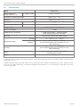
MICRO-EPSILON reflectCONTROL Sensor User manual
- Category
- Measuring & layout tools
- Type
- User manual
Ask a question and I''ll find the answer in the document
Finding information in a document is now easier with AI
Related papers
-
 MICRO-EPSILON eddyNCDT 3001 - U2 Assembly Instructions
-
 MICRO-EPSILON eddyNCDT 3001 - U6 U8 Assembly Instructions
-
 MICRO-EPSILON wireSENSOR WPS K100 User manual
-
 MICRO-EPSILON wireSENSOR WPS K100 Assembly Instructions
-
 MICRO-EPSILON wireSENSOR WPS-MK120 Assembly Instructions
-
 MICRO-EPSILON thermoMETER TIM 8 / thermoIMAGER TIM 40 Assembly Instructions
-
 MICRO-EPSILON wireSENSOR WPS-MK77 Assembly Instructions
-
 MICRO-EPSILON optoCONTROL 2600 Owner's manual
-
 MICRO-EPSILON ILD1700 User manual
-
 MICRO-EPSILON induSENSOR EDS- ... -F Series Assembly Instructions


Other documents
-
Emerson Epsilon EP Drive 400518-01 User manual
-
SICK Ranger3 3D Vision Operating instructions
-
Infinity IRS Epsilon Owner's manual
-
-
-
 Mono Epsilon 400 Operating And Maintenance Manual
-
Baumer VCXU-31C Operating instructions
-
-
-
Baumer VLXT-123M.FO Operating instructions
