Page is loading ...

User Guide
SF 10C SUB
Speakers
Ceiling-mounted Subwoofer
68-2870-01 Rev. A
03 19

Safety Instructions
Safety Instructions • English
WARNING: This symbol, , when used on the product, is intended to
alert the user of the presence of uninsulated dangerous voltage within the
product’s enclosure that may present a risk of electric shock.
ATTENTION: This symbol, , when used on the product, is intended
to alert the user of important operating and maintenance (servicing)
instructions in the literature provided with the equipment.
For information on safety guidelines, regulatory compliances, EMI/EMF
compatibility, accessibility, and related topics, see the Extron Safety and
Regulatory Compliance Guide, part number 68-290-01, on the Extron
website, www.extron.com.
Sicherheitsanweisungen • Deutsch
WARNUNG: Dieses Symbol auf dem Produkt soll den Benutzer darauf
aufmerksam machen, dass im Inneren des Gehäuses dieses Produktes
gefährliche Spannungen herrschen, die nicht isoliert sind und die einen
elektrischen Schlag verursachen können.
VORSICHT: Dieses Symbol auf dem Produkt soll dem Benutzer in
der im Lieferumfang enthaltenen Dokumentation besonders wichtige
Hinweise zur Bedienung und Wartung (Instandhaltung) geben.
Weitere Informationen über die Sicherheitsrichtlinien, Produkthandhabung,
EMI/EMF-Kompatibilität, Zugänglichkeit und verwandte Themen finden Sie in
den Extron-Richtlinien für Sicherheit und Handhabung (Artikelnummer
68-290-01) auf der Extron-Website, www.extron.com.
Instrucciones de seguridad • Español
ADVERTENCIA: Este símbolo, , cuando se utiliza en el producto,
avisa al usuario de la presencia de voltaje peligroso sin aislar dentro del
producto, lo que puede representar un riesgo de descarga eléctrica.
ATENCIÓN: Este símbolo, , cuando se utiliza en el producto, avisa
al usuario de la presencia de importantes instrucciones de uso y
mantenimiento recogidas en la documentación proporcionada con el
equipo.
Para obtener información sobre directrices de seguridad, cumplimiento
de normativas, compatibilidad electromagnética, accesibilidad y temas
relacionados, consulte la Guía de cumplimiento de normativas y seguridad
de Extron, referencia 68-290-01, en el sitio Web de Extron, www.extron.com.
Instructions de sécurité • Français
AVERTISSEMENT : Ce pictogramme, , lorsqu’il est utilisé sur le
produit, signale à l’utilisateur la présence à l’intérieur du boîtier du
produit d’une tension électrique dangereuse susceptible de provoquer
un choc électrique.
ATTENTION : Ce pictogramme, , lorsqu’il est utilisé sur le produit,
signale à l’utilisateur des instructions d’utilisation ou de maintenance
importantes qui se trouvent dans la documentation fournie avec le
matériel.
Pour en savoir plus sur les règles de sécurité, la conformité à la
réglementation, la compatibilité EMI/EMF, l’accessibilité, et autres sujets
connexes, lisez les informations de sécurité et de conformité Extron, réf.
68-290-01, sur le site Extron, www.extron.com.
Istruzioni di sicurezza • Italiano
AVVERTENZA: Il simbolo, , se usato sul prodotto, serve ad
avvertire l’utente della presenza di tensione non isolata pericolosa
all’interno del contenitore del prodotto che può costituire un rischio di
scosse elettriche.
ATTENTZIONE: Il simbolo, , se usato sul prodotto, serve ad avvertire
l’utente della presenza di importanti istruzioni di funzionamento e
manutenzione nella documentazione fornita con l’apparecchio.
Per informazioni su parametri di sicurezza, conformità alle normative,
compatibilità EMI/EMF, accessibilità e argomenti simili, fare riferimento
alla Guida alla conformità normativa e di sicurezza di Extron, cod. articolo
68-290-01, sul sito web di Extron, www.extron.com.
Instrukcje bezpieczeństwa • Polska
OSTRZEŻENIE: Ten symbol, , gdy używany na produkt, ma na celu
poinformować użytkownika o obecności izolowanego i niebezpiecznego
napięcia wewnątrz obudowy produktu, który może stanowić zagrożenie
porażenia prądem elektrycznym.
UWAGI: Ten symbol, , gdy używany na produkt, jest przeznaczony do
ostrzegania użytkownika ważne operacyjne oraz instrukcje konserwacji
(obsługi) w literaturze, wyposażone w sprzęt.
Informacji na temat wytycznych w sprawie bezpieczeństwa, regulacji
wzajemnej zgodności, zgodność EMI/EMF, dostępności i Tematy pokrewne,
zobacz Extron bezpieczeństwa i regulacyjnego zgodności przewodnik, część
numer 68-290-01, na stronie internetowej Extron, www.extron.com.
Инструкция по технике безопасности • Русский
ПРЕДУПРЕЖДЕНИЕ: Данный символ, , если указан на продукте,
предупреждает пользователя о наличии неизолированного опасного напряжения
внутри корпуса продукта, которое может привести к поражению электрическим
током.
ВНИМАНИЕ: Данный символ, , если указан на продукте,
предупреждает пользователя о наличии важных инструкций
по эксплуатации и обслуживанию в руководстве,
прилагаемом к данному оборудованию.
Для получения информации о правилах техники безопасности,
соблюдении нормативных требований, электромагнитной
совместимости (ЭМП/ЭДС), возможности доступа и других
вопросах см. руководство по безопасности и соблюдению
нормативных требований Extron на сайте Extron: ,
www.extron.com, номер по каталогу - 68-290-01.
安全说明 • 简体中文
警告: 产品上的这个标志意在警告用户该产品机壳内有暴露的危险 电压,
有触电危险。
注意: 产品上的这个标志意在提示用户设备随附的用户手册中有
重要的操作和维护(维修)说明。
关于我们产品的安全指南、遵循的规范、EMI/EMF 的兼容性、无障碍
使用的特性等相关内容,敬请访问 Extron 网站 , www.extron.com,参见
Extron 安全规范指南,产品编号 68-290-01
。

Copyright
© 2019 Extron Electronics. All rights reserved.
Trademarks
All trademarks mentioned in this guide are the properties of their respective owners.
The following registered trademarks(
®
), registered service marks(
SM
), and trademarks(
TM
) are the property of RGBSystems, Inc. or
ExtronElectronics (see the current list of trademarks on the Terms of Use page at www.extron.com):
Registered Trademarks
(
®
)
Extron, Cable Cubby, ControlScript, CrossPoint, DTP, eBUS, EDID Manager, EDID Minder, Flat Field, FlexOS, Glitch Free. Global
Configurator, GlobalScripter, GlobalViewer, Hideaway, HyperLane, IPIntercom, IPLink, KeyMinder, LinkLicense, LockIt, MediaLink,
MediaPort, NetPA, PlenumVault, PoleVault, PowerCage, PURE3, Quantum, Show Me, SoundField, SpeedMount, SpeedSwitch,
StudioStation, SystemINTEGRATOR, TeamWork, TouchLink, V-Lock, VideoLounge, VN-Matrix, VoiceLift, WallVault, WindoWall, XTP,
XTPSystems, and ZipClip
Registered Service Mark
(SM)
: S3 Service Support Solutions
Trademarks
(
™
)
AAP, AFL (Accu-RateFrameLock), ADSP(Advanced Digital Sync Processing), Auto-Image, AVEdge, CableCover, CDRS(ClassD
Ripple Suppression), Codec Connect, DDSP(Digital Display Sync Processing), DMI (DynamicMotionInterpolation), DriverConfigurator,
DSPConfigurator, DSVP(Digital Sync Validation Processing), eLink, EQIP, Everlast, FastBite, FOX, FOXBOX, IP Intercom HelpDesk,
MAAP, MicroDigital, Opti-Torque, PendantConnect, ProDSP, QS-FPC(QuickSwitch Front Panel Controller), RoomAgent, Scope-Trigger,
ShareLink, SIS, SimpleInstructionSet, Skew-Free, SpeedNav, Triple-Action Switching, True4K, Vector™ 4K , WebShare, XTRA, and
ZipCaddy
安全記事 • 繁體中文
警告: 若產品上使用此符號,是為了提醒使用者,產品機殼內存在著
可能會導致觸電之風險的未絕緣危險電壓。
注意 若產品上使用此符號,是為了提醒使用者,設備隨附的用戶手冊中有
重要的操作和維護(維修)説明。
有關安全性指導方針、法規遵守、EMI/EMF 相容性、存取範圍和相關主題的詳細資
訊,請瀏覽 Extron 網站:www.extron.com,然後參閱《Extron 安全性與法規
遵守手冊》,準則編號 68-290-01。
安全上のご注意
• 日本語
警告: この記号 が製品上に表示されている場合は、筐体内に絶縁されて
いない高電圧が流れ、感電の危険があることを示しています。
注意:この記号 が製品上に表示されている場合は、本機の取扱説明書に
記載されている重要な操作と保守(整備)の指示についてユーザーの注意
を喚起するものです。
安全上のご注意、法規厳守、EMI/EMF適合性、その他の関連項目に
つ い て は 、エ ク スト ロ ン の ウェ ブ サ イト www.extron.com よ り 『 Extron Safety
and Regulatory Compliance Guide』 ( P/N 68-290-01) をご覧ください。
안전 지침 • 한국어
경고: 이 기호 가 제품에 사용될 경우, 제품의 인클로저 내에 있는
접지되지 않은 위험한 전류로 인해 사용자가 감전될 위험이 있음을
경고합니다.
주의: 이 기호 가 제품에 사용될 경우, 장비와 함께 제공된 책자에 나와
있는 주요 운영 및 유지보수(정비) 지침을 경고합
니다.
안전 가이드라인, 규제 준수, EMI/EMF 호환성, 접근성, 그리고 관련 항목에
대한 자세한 내용은 Extron 웹 사이트(www.extron.com)의 Extron 안전 및
규제 준수 안내서, 68-290-01 조항을 참조하십시오.

FCC Class A Notice
This equipment has been tested and found to comply with the limits for a Class A digital
device, pursuant to part15 of the FCC rules. The ClassA limits provide reasonable
protection against harmful interference when the equipment is operated in a commercial
environment. This equipment generates, uses, and can radiate radio frequency energy
and, if not installed and used in accordance with the instruction manual, may cause
harmful interference to radio communications. Operation of this equipment in a
residential area is likely to cause interference. This interference must be corrected at the
expense of the user.
ATTENTION: The Twisted Pair Extension technology works with shielded twisted
pair (STP) cables only. To ensure FCC Class A and CE compliance, STP cables
and STP Connectors are also required.
For more information on safety guidelines, regulatory compliances, EMI/EMF
compatibility, accessibility, and related topics, see the “Extron Safety and
Regulatory Compliance Guide” on the Extron website.
Conventions Used in this Guide
Notifications
The following notifications are used in this guide:
WARNING: Potential risk of severe injury or death.
AVERTISSEMENT : Risque potentiel de blessure grave ou de mort.
CAUTION: Risk of minor personal injury.
ATTENTION : Risque de blessuremineure.
ATTENTION:
• Risk of property damage.
• Risque de dommages matériels.
NOTE: A note draws attention to important information.
TIP: A tip provides a suggestion to make working with the application easier.
Specifications Availability
Product specifications are available on the Extron website, www.extron.com.
Extron Glossary of Terms
A glossary of terms is available at http://www.extron.com/technology/glossary.aspx.

vSF 10C SUB • Contents
Contents
Introduction............................................................ 1
About this Guide ................................................. 1
About the SF 10C SUB ...................................... 1
Features ............................................................. 3
Installation .............................................................. 4
Placement Considerations .................................. 4
Installation Environment .................................. 4
Acoustical Reinforcement ............................... 5
Mounting the Subwoofer .................................... 6
Suspending in the Ceiling ............................... 6
Resting on a Floor ........................................ 11
Mounting the Port Tube .................................... 13
Installing the Grille ............................................. 13
Connection and Operation ................................ 15
Connection ................................................... 15
Operational Considerations ........................... 17
Troubleshooting ................................................ 18

SF 10C SUB • Contents vi

SF 10C SUB • Introduction 1
Introduction
• About this Guide
• About the SF 10C SUB
• Features
About this Guide
This guide describes the Extron SF 10C SUB, a subwoofer, that is typically installed above
a suspended ceiling. This guide describes how to install, operate, and configure the
subwoofer.
About the SF 10C SUB
The SF 10C SUB (see figure 1 on the next page) is a plenum-rated, 8 ohm, 4th order band-
pass subwoofer with a tuned bass-reflex port. When installed, the subwoofer is typically
suspended by wire from the structural ceiling above the suspended ceiling. This avoids
unwanted rattling and vibrating in the ceiling tile grid. It features a 10 inch ported woofer
housed within a cylindrical enclosure. A right-angle port on the front of the enclosure directs
the sound waves into the listening area.
The subwoofer has a frequency range of 25 Hz to 160 Hz, -10 dB, half space.
The SF 10C SUB is compatible with any Extron low impedance amplifier with sufficient
output drive power. The unit is UL 2043 listed for use in air-handling spaces.
The subwoofer is intended for use in a bi-amplified system. Separate amplifiers should
power the low and high frequencies.
The SF 10C SUB is UL Listed for use in plenum airspaces: meets UL 2043 for heat and
smoke release.
Suitable for use in environmental air space in accordance with Section 300-22(C) of
the National Electrical Code, and Sections 2-128, 12-010(3) and 12-100 of the Canadian
Electrical Code, Part 1, CSA C22.1. The product has been additionally investigated to
UL 2043, "Fire Test for Heat and Visible Smoke Release for Discrete Products and Their
Accessories Installed in Air-Handling Spaces".

SF 10C SUB • Introduction 2
DIGITAL MATRIX PROCESSOR
CONFIG
CLIP
EXP LAN USB
SIGNAL
CLIP
SIGNAL
1 2 3 4 5 6 7 8 1 2 3 4 5 6 7 89 10 11 12
ACTIVITY
INPUTS OUTPUTS
DMP 128 Plus
XPA 4002
LIMITER / PROTECT
SIGNAL
1
OVER
TEMP
2
GREEN - ACTIVE
AMBER - STANDBY
e
XPA U 1002 SERIES
12
OVER
TEMP
LIMITER/PROTECT
SIGNAL
POWER AMPLIFIERS
mute select
Extr
on
SF 3P
T
Pe
ndant
Spea
kers
Extron
DMP 128 Plus C V
Digital Matrix Processor
Extron
XPA U 1002-70V
Power Amplier
Audio
Audio
Audio
USB Audio
Audio
(Channel 2)
Audio
(Channel 1)
Audio
(Channel 1 and 2 bridged)
PC
Microphone
Table Microphones
Extron
SF 10C SUB
Subwoofer
Extron
XPA 4002
Power Amplier
Figure 1. Typical SF 10C SUB Application

SF 10C SUB • Introduction 3
Features
• 10-inch (254 mm) low frequency driver with a tuned port — Designed specifically
for low frequency extension.
• UL 2043 rated, rigid composite enclosure — Enclosure remains out of view when
suspended above the ceiling grid.
• Frequency range: 25 Hz to 160 Hz
• 800 watts continuous program
400 watts continuous pink noise — Power capacity per IEC 60268-5
• 8 ohm operation — Direct low impedance power avoids low frequency transformer
distortion.
• Suspension mounting above the ceiling structure greatly reduces rattle —
Physically isolated from the ceiling grid, low frequency vibrations are not transferred to
loose structural components.
• 4th order bandpass enclosure design — High output with controlled and clean low
frequency extension
• No crossover needed when used with SF 26CT, SF 3C LP, or SF 3CT LP ceiling
speakers — Eliminates phase problems at a crossover point.
• Includes installation and suspension hardware — Four sets of 15-foot (4.6 m)
steel cables with locking adapters are used to raise the SF 10C SUB into place and
suspend it.
• Includes C-ring and paintable grille — Port output into the room blends in with
ceiling speakers.
• Paintable enclosure — The SF 10C SUB enclosure can be painted with a plastic-
friendly paint.
• Integrated flame arrester for safety — Restricts flammability for plenum installations.
• 5-year parts and labor warranty

SF 10C SUB • Installation 4
Installation
This section describes the installation and the operation of the SF 10C SUB, including:
• Placement Considerations and Acoustical Reinforcement
• Mounting the Subwoofer
• Mounting the Port Tube
• Installing the Grille
• Connection and Operation
• Troubleshooting
Placement Considerations and Acoustical Reinforcement
Installation Environment
Ceiling placement
• The speaker is rated for installation in plenum spaces.
• The mounting kit comes with four sets of aircraft cables and cable gripper mounting
hardware for suspending the speaker in a horizontal orientation.
• Mounting holes for mounting using unistruts or all thread rods are provided.
• Isolation grommets are provided that dampen mechanical vibrations from the
subwoofer to the rest of the structure.
• Other than the isolation grommets, the installer must provide the mounting
hardware for unistrut or all thread rod installation.
• The mounting holes can also accept hanger wire.
• The port tube does not isolate the listening space from the installation space.
Bleed-over into adjacent rooms must be taken into consideration.
Placement behind a wall
• When the subwoofer is installed behind a wall, the port tube must be located as close
to the wall surface facing the listening space as possible.
• The drywall facing the subwoofer may need to be removed between the studs on either
side of the unit, in order to bring the port tube as close as possible to the front surface
of the wall. In this case, fire blocks must be run in-between the studs, to seal off the
space above the removed portion of the wall.
• The optional SMK F SF 10C floor mounting kit must be used when the subwoofer is
placed on the floor and must be strapped to a stud.

SF 10C SUB • Installation 5
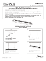
Acoustical Reinforcement
Depending on where you mount the subwoofer, such as next to a large, rigid planar surface,
you can achieve some level of acoustical reinforcement (see figure 2).
NOTE: At the frequencies at which the subwoofer operates, fiberglass ceiling tiles are
acoustically transparent and offer little acoustical reinforcement.
Corner Mounting
(π/2)
Edge Mounting
(π)
Ceiling Mounting
(2π)
Free Mounting
(4π)
Figure 2. Mounting Locations for Discussion of Acoustical Reinforcement

SF 10C SUB • Installation 6
• Corner mounting (see figure 2 on the previous page) — The subwoofer is mounted
in a corner of a surface where three surfaces meet, giving reinforcement from all three
surfaces. This option provides the most reinforcement. The port tube should be as close
to the corner as possible for best results.
• Edge mounting (see figure 2) — The subwoofer is mounted at the edge of a surface
where two surfaces meet, giving reinforcement from both surfaces. This option is as
much as 6 dB less sensitive than corner mounting. The port should be as close to the
wall as possible for best results.
• Ceiling, wall, or floor mounting (see figure 2) — The subwoofer is mounted in or on
a surface in an area away from any other surface. This option is as much as 12 dB less
sensitive than corner mounting. There is reinforcement from only one surface.
• Free mounting (see figure 2) — The subwoofer is mounted away from all walls,
the floor and the ceiling. This option is as much as 18 dB less sensitive than corner
mounting. There is no reinforcement from any surface.
Mounting the Subwoofer
The SF 10C SUB can be suspeded in a ceiling or rested on the floor.
Suspending in the Ceiling
WARNING:
AVERTISSEMENT :
• Properly suspending equipment requires training and expertise. Improper rigging of
suspended equipment can cause the speaker to fall, resulting in death, personal
injury, equipment damage, and legal liability. Installation must be carried out by fully
qualified installers, in accordance with all required safety codes and standards at
the place of installation.
• Il est indispensable de disposer de compétences techniques pour pouvoir
suspendre l’équipement. Une manipulation incorrecte de l’équipement suspendu
peut provoquer la chute de l’enceinte, entraînant la mort, des lésions corporelles,
des dégâts matériels, et engageant la responsabilité d’un individu. L’installation doit
être effectuée par des installateurs hautement qualifiés, conformément à l’ensemble
des codes et des normes de sécurité réglementaires sur le lieu de l’installation.
• The legal requirements for suspending equipment vary from country to country.
Extron strongly recommends that you consult your local safety standards office
before installing any product. Extron also recommends that you thoroughly check
any laws and bylaws prior to installation.
• Les conditions juridiques relatives à la suspension d’équipements varient de pays
en pays. Extron vous recommande vivement de consulter les standards de sécurité
en vigueur dans votre pays avant d’installer un produit. Extron vous recommande
également de vérifier minutieusement toute loi et tout règlement avant l’installation.
ATTENTION:
• Installation and service must be performed by authorized personnel only.
• L’installation et l’entretien doivent être effectués par le personnel autorisé
uniquement.
• This unit must be repaired by personnel trained by Extron or returned to Extron for
repair.
• Cette unité doit être réparée par un technicien formé par Extron ou renvoyée à
Extron pour réparation.

SF 10C SUB • Installation 7
The subwoofer can be suspended using the included aircraft cables (see “Aircraft cable
installation”) or, optionally, with threaded rods acquired locally (see Threaded rod
installation on page 10).
Aircraft cable installation
Suspend the subwoofer above a false ceiling using the included aircraft cables as follows:
Remove ceiling tile and install suspension cables.
For installation with optional threaded rods, see Threaded rod installation.
1. Determine where the subwoofer is to be suspended and its orientation above the
suspended ceiling.
NOTE: Remember that the sound from the unit is directed out the port. Therefore,
although you can suspend the subwoofer in any horizontal orientation, the port
needs to be pointed into the listening space.
Consider the following as you make this determination:
• Possible acoustical reinforcement (see Acoustical Reinforcement on page 5).
• The size (length, width, and height) of the subwoofer.
• The desired location of the woofer port. Ensure that the center of the port tube will
be at least 5-3/16 inches (13.7 cm) from the edge of suspended ceiling tile once
that tile is installed.
NOTE: This positioning ensures that the grille adapter and C-ring fit properly
once installed (see figure 3).
Do not install the C-ring
beyond the edge of ceiling tile.
Figure 3. Grille Adapter and C-ring Fit
• Any obstructions above the suspended ceiling that could constrain the orientation
of the suspended subwoofer.
2. At the location where the subwoofer is to be installed, remove as many ceiling tiles as
necessary to install the subwoofer.
NOTE: The number of tiles to remove depends on the height of the structural ceiling
above the suspended ceiling, given the 10-degree spread from the subwoofer to
the structural ceiling.

SF 10C SUB • Installation 8
3. At an approximate angle of 10 degrees out from each corner of
where the subwoofer will be installed, mark and drill four holes in the
structural ceiling for the suspension cable anchors.
4. Screw a lag eye bolt (or an appropriate anchor) into each hole.
5. Thread the loose end of the suspension cable through the bolt eyehole,
pass the loose end of the cable through the looped end and tighten.
Allow each cable to hang.
Suspend the main subwoofer enclosure from the ceiling
ATTENTION: The SF 10C SUB is heavy, approximately 38 pounds (17 kg), and bulky.
ATTENTION : La SF 10C SUB est lourde, et pèse environ 17 kg (38 livres), et est
volumineuse.
• Use at least two people to install the subwoofer; one person to lift the unit into
position AND to hold it, the second person to fasten the suspension cables.
• Il faut au minimum deux personnes pour installer le caisson de grave ; la première
pour mettre l’unité en place ET la tenir, et la seconde pour raccorder les câbles de
suspension.
• Consider using a scissor-lift or other lifting apparatus rather than a ladder to work in
the ceiling.
• Songez à utiliser une nacelle élévatrice ou tout équipement similaire plutôt qu’une
échelle pour travailler au plafond.
• Do not rest the subwoofer on the ceiling grid, even temporarily.
• Ne posez pas le caisson de grave sur la grille de plafond, même temporairement.
TIP: If a scissor-lift is not available, the speaker can be hoisted using the suspension
cables.
1. Remove the grommets from all four corners of the subwoofer frame (see figure 4 on
the next page).
2. Install the included eyebolts into the four holes on the four corners of the subwoofer
frame. Secure the eyebolts in place with the provided locking nuts (see figure 4).
3. With the help of at least one other person, carefully lift the subwoofer enclosure into the
installation location.
4. Holding a cable gripper, pass the loose end of one of the cables down through one hole
of the gripper. Ensure that about 12 to 15 inches (30 to 38 cm) of cable has exited the
gripper (see figure 4).
WARNING:
AVERTISSEMENT :
• Maintain at least a 2 inch (5 cm) clearance between the plunger on the cable
gripper and any other object in the ceiling space. This includes the space
between the eyebolt below the gripper and the mounting hardware above the
gripper. If an object strikes the plunger, the cable gripper could disengage and
allow the subwoofer to fall.
• Conservez au minimum 5 cm (2”) d’espace libre entre le piston sur le serre-
câble et tout autre objet se trouvant dans l’espace plafond. Il s’agit de l’espace
entre l’anneau de levage sous le serre-câble et le matériel de montage au-
dessus du serre-câble. Si un objet heurte le piston, le serre-câble pourrait se
desserrer et entraîner la chute du caisson de basses.

SF 10C SUB • Installation 9
Thread the cable down through the cable gripper, through the ey
e
of one of the eyebolts, and back up through the lock.
Cable
Gripper
Plunger
Eyebolt
≥2"
(50 mm)
≥1"
(25 mm)
≥2"
(50 mm)
Countersunk
Washer
Locking Nut
(not shown)
Figure 4. Installing the Subwoofer with the Included Steel Cables
5. Pass the loose end of the cable through the eye of one of the eye bolts on the
subwoofer enclosure and then through the other hole in the cable gripper. Ensure that
at least 1 inch (15 cm) of cable comes through the other end of the gripper.
6. Repeat steps 4 and 5 for each corner.
7. Adjust the cable tension through all cable grippers so that the subwoofer appears level
to the critical eye and to ensure that its bottom brackets will be approximately 1 inch
(2.5 cm) from the top surface of suspended ceiling tile once that tile is installed.
NOTE: The exact height of the subwoofer is not critical at this point. You will make
final adjustments after the grille is installed.

SF 10C SUB • Installation 10
Threaded rod installation
Secure the subwoofer to the structural ceiling using threaded rods as follows:
NOTES:
• Extron recommends 1/4-inch or 3/8-inch diameter threaded rods for installing this
product.
• The threaded rod must be properly secured to the ceiling structure. For example,
properly fasten a unistrut to the ceiling structure and attach threaded rods using
nuts and fender washers.
1. Fasten four threaded rods to the support structure. Extron recommends fastening the
rods to unistruts, one over each corner of the subwoofer installation location.
2. Fasten a rod to each corner securing point of the
Insert threaded
rods through holes
on the ends of the
mounting bracket.
Attach washer and nut and secure.
subwoofer with nuts and fender washers
(see the figure at right).
3. Adjust all the nuts that secure the subwoofer to the
ceiling so that the subwoofer appears level to the
critical eye and to ensure that its bottom brackets
will be approximately 1 inch (2.5 cm) from the top
surface of suspended ceiling tile once that tile is
installed.
NOTE: The exact height of the subwoofer above
the ceiling is not critical at this point. You
will make final adjustments after the grille is
installed.

SF 10C SUB • Installation 11
Resting on a Floor
ATTENTION:
• The SF 10C SUB must have firebreaks installed in the wall, above and below it,
when it is protruding through a wall, to meet UL requirements.
• Le SF 10C SUB doit disposer de systèmes coupe-feu installés au mur, au-dessus
et au-dessous de l’unité, lorsqu’elle est placée en saillie du mur, afin de satisfaire les
exigences de l’UL.
• The subwoofer must be securely fastened to the stud or other stationary surface.
• Le caisson de grave doit être solidement fixé au montant ou à une autre surface
stationnaire.
The subwoofer can be rested on a floor using the optional SMK F SF 10C floor mounting kit,
as follows:
1. Determine where the subwoofer is to be placed and its orientation (port tube on top or
port tube on the bottom).
NOTE:
• Remember that the sound from the unit is directed out the port. Therefore, the
port needs to be pointed into the listening space.
• To ensure that the Extron grille fits fully into any masking wall or other partition,
the center of the port tube must be at least 5-3/16 inches (13.7 cm) from the
edge of the wall.
• The grille will not fit if you install the feet on the subwoofer with the port
tube down. Consider fabricating a small platform to lift the subwoofer (see
figure 6,
1
on the next page) or otherwise design your own way to dress the
installation to give your installation a finished look.
• Steps 3, 4, 5, and 8 are only necessary if you are installing the subwoofer in an
adjoining space.
2. Fasten two feet to each installation bracket using the provided screws and locking nuts,
two on one side of the foot (see figure 5,
1
), and one on the other side (
2
).
11111111111111
11111111111111
22222222222222 22222222222222
Figure 5. Installing a Floor Mounting Kit
3. When installing in an adjoining space — On the far side of the wall (outside the
listening space), remove enough wall material so that the subwoofer port tube can be
placed as close to the wall (facing the listening space) as possible.

SF 10C SUB • Installation 12
4. When installing in an adjoining space — On the near side of the wall (inside the
listening space), mark where the center of the port tube faces the installation surface.
The center mark must be at least 5-3/16 inches (13.7 cm) from the edge of the
installation surface (see figure 3 on page 7) if the grille will be used (see Installing the
Grill on page 13).
5. When installing in an adjoining space — On the near side of the wall (inside the
listening space), mark and cut the hole in the surface.
6. Place the subwoofer in the desired location.
7. Use a locally-obtained perforated metal hanger strap to secure two of the mounting holes
on the top bracket to the nearest stud or other stationary surface (see figure 6,
2
).
2222
Listening Space
Installation Location
(Adjoining Space)
1111
3333
Figure 6. Securing the Floor-mounted Subwoofer and Installing Fire Breaks
8. When installing in an adjoining space — Ensure that there are fire breaks above and
below the port tube (
3
) to meet UL requirements. If necessary, fabricate them.

SF 10C SUB • Installation 13
Mounting the Port Tube
1. Orient the port tube so that it is pointed into the listening space (see figure 7).
Mounting Screws
(4 places)
Figure 7. Installing the Port Tube
2. Using the included hardware, mount the port tube to the speaker.
Installing the Grille
NOTE: For ceiling tile installation, if the ceiling tile is not removed for the subwoofer
installation, remove it.
1. If not already accomplished, on the installation surface, mark where the center of the
port tube faces the installation surface. The center mark must be at least 5-3/16 inches
(13.7 cm) from the edge of the installation surface.
2. If not already accomplished, using the included grille cut-out template, mark and cut the
hole in the surface.
3. For ceiling tile installation, replace the ceiling tile in the grid.
4. Place the C-ring on the subwoofer side of the installation surface and center it over the
hole.
5. Place the grille adapter on the opposite side of the installation surface (see figure 8 on
the next page) and use a Phillips screwdriver to turn the three locking arms to loosely
mate the adapter to the C-ring.

SF 10C SUB • Installation 14
Locking Arms
Figure 8. Installing the Grille Adapter
6. Rotate the C-ring and grille adapter such that the locking arms do not collide with the
subwoofer.
7. Use a Phillips screwdriver to tighten the three locking arms to clamp the adapter to the
C-ring.
NOTE: For installation in rigid vs. soft material:
• Rigid material — Three locking arm screws use
Opti-Torque indicator rings that snap and
separate from their plastic rings when the screws
are tightened to the correct torque. The indicator
ring falls down the screwdriver shaft. When this
occurs, stop tightening the screw to avoid
overtightening the locking arms to the C-ring
(see the figure at right).
• Soft material — Because fiberglass ceilings
and other soft materials are not as rigid
as mineral tiles and other hard materials,
the Opti-Torque indicator should not be
used as a tightening guide due to the risk
of overtightening. See the ATTENTION below.
ATTENTION:
• To avoid damaging or
deforming soft ceiling
material, tighten the locking
arms to secure the grille
X
adapter, but short of causing the grille adapter to deform the flat mounting
surface of the ceiling, as seen from below.
• Afin de ne pas endommager ni altérer un plafond souple, serrez les bras de
verrouillage pour sécuriser l’adaptateur en grille, en veillant cependant à ce que
l’unité ne cause l’altération de la surface de montage plane du plafond, comme
illustré ci-dessous.
/