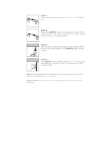
Ledalite Driver Pod Install Instructions

Category
Wall & ceiling mounts accessories
Type
Install Instructions

This manual is also suitable for

Ledalite Driver Pod is a versatile device designed to provide efficient and reliable power to LED luminaires in various lighting applications. With its advanced features and easy installation process, it offers a range of benefits for users:

  • Flexible Configuration: The Driver Pod allows for customization to suit specific lighting requirements. It can be used with either one or two drivers, enabling users to choose the appropriate configuration for their project.

  • Dimming Control Compatibility: The device is compatible with dimming control systems, providing users with the ability to adjust light levels smoothly and seamlessly. This flexibility enhances the ambiance and energy efficiency of the lighting installation.

ATTENTION: Install in accordance with national and local building and electrical codes.
!
!
IMPORTANT SAFETY AND HANDLING PROCEDURES
DO NOT POWER UP ROW UNTIL ALL FIXTURES ARE INSTALLED AND CONNECTED
PAGE 1
Ground
Line Voltage
Low Voltage
Control Wires
Ground
Line Voltage
Low
Volage
Control
Wires
Red (+)
Red/White (+)
Blue (-)
Blue/White (
-)
Red (+)
Blue (-)
Blue (-)
Red (+)
Blue/White (-)
Red/White (+)
To LED Luminaire
To LED Luminaire
Driver Pod with One Driver
Driver Pod with Two Drivers
Will only have one pair of Red and
Blue or Red/White and Blue/White
and will terminate in 3 pole connector.
Connect all reds together.
Connect all blues together.
If installaon of a sensor is required,
refer to page 2 for wiring instrucons.
Connect building power.
Red (+)
Red/White (+)
Blue/White (
-)
Blue (-)
To Building Power
To Building Power
Will have two pairs of Red and Blue or
Red/White and Blue/White and will
terminate in 2 pole connector.
Connect one pair of wires from the driv-
er pod to red and blue wires.
Connect other pair of wires from the
driver pod to red/white and blue white.
If installaon of a sensor is required,
refer to page 2 for wiring instrucons.
Connect building power.
ATTENTION: Install in accordance with national and local building and electrical codes.
!
!
IMPORTANT SAFETY AND HANDLING PROCEDURES
DO NOT POWER UP ROW UNTIL ALL FIXTURES ARE INSTALLED AND CONNECTED
PAGE 2
Driver Pod with One Driver and Sensor
Driver Pod with Two Drivers and Sensor
To connect sensor, open driver pod housing cover and
locate purple and brown dimming control wires.
Connect driver pod purple (+) wire to sensor red (+) wire
using supplied connector.
Connect driver pod brown (-) wire to sensor white (-) wire
using supplied connector.
Install driver pod cover and connect building power.
To connect sensor, open driver pod housing cover and locate
purple and brown dimming control wires.
Connect driver pod purple (+) wire to sensor red (+) wire
using supplied connector.
Connect driver pod brown (-) wire to sensor white (-) wire
using supplied connector.
Install driver pod cover and connect building power.
EASYSENSE
SENSOR
Driver Pod 2 Pole Connectors (Supplied)
ATTENTION: Install in accordance with national and local building and electrical codes.
!
Page 1
1
IMPORTANT: Refer to supplied layout draw-
ings to determine exact mounting locations.
IMPORTANT: All mount locations require a 4-
1/2” hole cut in drywall ceiling.
Mount Installation
2
Top Plate Installation
3
Top Plate Installation
4
Threaded Rod Installation
5
Bottom Plate Installation
6
Bottom Plate Installation 7
Canopy/Cable Gripper Installation
8 Suspension Cable Installation
R1 mounng system is designed to
work with 1/2” and 5/8” drywall. Mini-
mum plenum height of 8-1/2” is re-
quired for power mount installaon.
Non-power mount installaon is cov-
ered in steps 2 to 9 of this document.
Power mount installaon is covered, in
steps 11 to 23 of this document.
Begin threading factory prepared stud assembly into
top plate. IMPORTANT: Stop after approximately 1
inch and move to next step.
Slide canopy onto 1/4”-20 and install cable gripper.
IMPORTANT: Fully tighten cable gripper against
canopy and 1/4”-20 nut below bottom plate.
top plate
Drill 4-1/2” diameter hole at required mounting
location.
From below, tilt and insert top plate inside ceiling .
1/4”-20 nut
Thread bottom plate assembly into top plate until full
contact with bottom of drywall sheet. If needed,
rotate slightly, align slot in bottom plate with hole in
top plate and attach screw supplied in hardware kit.
Center top plate above ceiling hole as shown.
Slide bottom plate onto 1/4”-20 stud assembly.
Install 1/4”-20 supplied in hardward kit and fully
tighten bottom plate against stud assembly.
IMPORTANT: Ensure bottom plate is fully secured.
Insert suspension cable inside cable gripper and push
through exit side. IMPORTANT: Ensure end of
suspension cable is visible through exit port of cable
gripper.
boom plate
stud assembly
suspension cable
cable gripper
canopy
ATTENTION: Install in accordance with national and local building and electrical codes.
!
Page 2
9
IMPORTANT: Cable adjustment is done by press-
ing release spring. CAUTION: Ensure fixture is
fully supported before any adjustments are made.
After final adjustments, trim excess cable below
canopy.
10
To complete fixture installation, refer to supplied
fixture installation instructions and layout drawings.
Fixture Installation
11
Driver Pod Wiring
12
Begin driver pod installation by tilting and guiding
through ceiling hole.
Driver Pod Installation
13
Driver Pod Installation
14a
Move driver pod back and position directly above
ceiling access hole.
Note: Above ceiling view shown for reference only.
Driver Pod Installation 14b
Make sure driver pod is centered above ceiling ac-
cess hole.
Driver Pod Installation
15 Mount Preparation—1/2” Drywall
Refer to supplied xture
installaon instrucons.
For 1/2” drywall ceilings only, assemble 1/4”-20 bolt
and nut supplied in hardware kit.
For 5/8” drywall ceilings use only 1/4”-20 bolt for
next step.
Suspension Cable Adjustment
release spring
Drill a 4-1/2” hole at required mounting location.
Prepare power feed conduit (supplied by others)
and pull through ceiling hole. Connect conduit
and connectors to 7/8” hole on A/C side of
driver pod. Tuck wires inside A/C wiring cavity.
While feeding driver pod through ceiling hole, tilt
upper section forward and lower section back to
fully insert above ceiling.
Note: above ceiling view
1/4”-20 bolt
1/4”-20 nut
electrical conduit
Note: below ceiling view
IMPORTANT
ATTENTION: Install in accordance with national and local building and electrical codes.
!
Page 3
16
Mounting Bolt Installation
17
18
Install 1/4”-20 nut supplied in hardware kit.
IMPORTANT: Leave a 1/4” gap at the bottom for
cable gripper attachment. Install cable gripper onto
stud. Ensure cable gripper is fully tightened against
1/4”20 nut.
Slide canopy and bottom plate on suspension cable
and lower to fixture level. Insert suspension cable
inside gripper and push through exit side.
IMPORTANT: Ensure end of suspension cable is
visible through exit port of cable gripper.
Suspension Cable Installation
20
Refer to supplied fixture installation instructions for
proper installation. Once fixtures are installed, make
any necessary adjustments at the cable gripper by
pushing release spring. IMPORTANT: Ensure fix-
ture sections are fully supported before adjustments
are made.
Suspension Cable Adjustment
21
Feed fixture power cord through bottom plate
and lower plate to fixture level. Complete low
voltage wiring connections inside driver pod wir-
ing cavity. Raise bottom plate to ceiling and se-
cure to driver pod with supplied screws.
Fixture Power Cord Installation
22
23
Push canopy tight against drywall ceiling and tighten
collar set screw to lock in place.
Canopy Installation
Install 1/4”20 bolt through driver pod wiring cavity
and pull through center hole as shown.
1/4” gap
suspension cable
Canopy Installation
Cable Gripper Installation
1/4”-20 nut
cable gripper
canopy
boom plate
release spring
Raise canopy and collar to ceiling.
power cord
23
To complete fixture installation, refer to supplied
fixture installation instructions and layout drawings.
Fixture Installation
Refer to supplied xture
installaon instrucons.
collar
ATTENTION: Install in accordance with national and local building and electrical codes.
!
Page 1
1
IMPORTANT: Refer to supplied layout draw-
ings to determine exact mounting locations.
Mount Installation
2
Housing Installation
3
Install housing at required mounting location.
Attach to structure with appropriate hardware
(supplied by others).
Housing Installation
4
Housing Installation
5
Prepare 1/4”-20 bolt for installation by attaching
1/4”-20 nut supplied in mounting kit.
Ensure nut is flush with head of bolt as shown.
Mount Preparation
6
Install bolt prepared in step 5 inside mounting brack-
et hole as shown.
Install second 1/4”-20 to secure to mounting bracket.
IMPORTANT: Ensure nut is fully tightened to bolt.
Mount Installation 7
Cable/Cable Gripper Installation
8
Insert suspension cable inside cable gripper and push
through exit side. IMPORTANT: Ensure end of
suspension cable is visible through exit port of cable
gripper.
Suspension Cable Installation
Non-power mount instal-
laon is covered in steps
2 to 10 of this document.
Power mount installaon
is covered, in steps 12 to
22 of this document.
IMPORTANT: Ensure housing is secure to ceiling.
IMPORTANT: Feed suspension cable through hous-
ing cover removed in step 2. Install spacer and cable
gripper onto housing 1/4”-20 bolt and fully tighten.
IMPORTANT: Fully tighten cable gripper against
spacer and 1/4”-20 bolt.
spacer
cable gripper
suspension cable
housing cover
Remove housing cover and 2 screws.
1/4”-20 nut
ATTENTION: Install in accordance with national and local building and electrical codes.
!
Page 2
9
Slide housing cover up and over cable gripper.
Housing Cover Installation
10
Re-install housing cover and screws removed in step
2. Cable adjustment is done by pressing release
spring. Ensure fixture is fully supported before any
adjustments are made. After final adjustments, trim
excess cable below cover.
Suspension Cable Adjustment
11
To complete fixture installation, refer to included
fixture installation instructions and layout drawings.
Fixture Installation
12
Remove driver pod housing and 4 screws.
Driver Pod Installation
13
Install driver pod at required mounting location.
Attach to structure with appropriate hardware
(supplied by others).
Driver Pod Installation
14
Determine required power feel location. Remove
7/8” knockout in housing and attach electrical con-
duit (supplied by others).
Power Feed Preparation 15
Prepare 1/4”-20 bolt for installation by attaching
1/4”-20 nut supplied in hardware kit.
Ensure nut is flush with head of bolt as shown.
Mount Preparation
16 Mount Installation
Refer to supplied xture
installaon instrucons.
release spring
Insert bolt assembly inside mounting bracket and
push through.
IMPORTANT: Ensure bolt location is as shown.
ATTENTION: Install in accordance with national and local building and electrical codes.
!
Page 3
17
Cable Gripper Installation
18
19
Feed suspension cable through housing cover re-
moved in step 12. Insert cable inside cable gripper
and push through exit side. IMPORTANT: Ensure
end of suspension cable is visible through exit port
of cable gripper.
Feed fixture power cord through driver pod cover
and driver pod housing mounting bracket. Pull ex-
cess cable inside housing. Trim as needed and com-
plete low voltage wiring connections inside driver
pod housing.
Power Cord Installation
20
Refer to supplied fixture installation instructions for
proper installation. Once fixtures are installed, make
any necessary adjustments at the cable gripper by
pushing release spring. IMPORTANT: Ensure fix-
ture sections are fully supported before adjustments
are made.
Suspension Cable Adjustment
21
Raise cover to ceiling and align with suspension
cable and cable gripper
Cover Installation
22
23
To complete fixture installation, refer to supplied
fixture installation instructions and layout drawings.
Fixture Installation
1/4”-20 nut
spacer
cable gripper
Install 1/4”20 nut and fully tighten against mounting
bracket. Install spacer and cable gripper to 1/4”-20
stud. IMPORTANT: Fully tighten cable gripper
against spacer and 1/4”-20 nut.
suspension cable
xture power cord
release spring
Secure cover to driver pod housing with 4 screws
removed in step 12.
Refer to supplied xture
installaon instrucons.
Cover Installation
Suspension Cable Installation
ATTENTION: Install in accordance with national and local building and electrical codes.
!
Page 1
1
Refer to supplied layout drawings to determine
exact mounting locations.
Mount Installation 2
Ceiling Tile Preparation
3
Spanner Bar Installation
4
Install supplied 1/4”-20 bolt, nut and 2 washers
as shown. Center above mounting hole and fully
tighten to Caddy spanner bar.
Hardware Installation
5
Spanner Bar Installation
6
IMPORTANT: Ensure bottom of nut is 9/16” away
from end of 1/4-20 bolt.
Suspension Cable Installation
7
Cable Gripper Installation
8 Suspension Cable Installation
Non-power mount instal-
laon is covered in steps
2 to 9 of this document.
Power mount installaon
is covered in steps 11 to
19 of this document.
ceiling le
Attach tie off cables (supplied by others) to sup-
port spanner bar to structure. From below ceil-
ing, install second 1/4”-20 nut onto 1/4”-20 bolt.
IMPORTANT: Lock spanner bar to t-grid using
appropriate hardware (supplied by others).
Remove adjacent ceiling tile. From above ceiling,
locate supplied Caddy spanner bar above mounting
location and snap to t-bar grid.
Insert suspension cable inside gripper and push
through exit side.
IMPORTANT: Ensure end of suspension cable is
visible through exit port of cable gripper.
Install canopy, spacer and cabler gripper as
shown. IMPORTANT: Fully tighten gripper
against 1/4”-20 bolt. From above ceiling, tighten
nut against canopy to secure all components.
Refer to supplied layout drawings to determine
exact mount location.
From below ceiling, using a hole saw, drill a 1-1/2
or 2” hole in tle at required mounting location.
9/16” gap
9/16” gap
cable gripper
canopy
suspension
cable
e o cable
spacer
screw
ATTENTION: Install in accordance with national and local building and electrical codes.
!
Page 2
9
Suspension Cable Adjustment
10
To complete fixture installation, refer to supplied
fixture installation and layout drawings.
Fixture Installation
11
Refer to supplied layout drawings to determine
exact mount location.
From below ceiling, using a hole saw, drill a 3” hole
in ceiling tile at required mounting location.
Ceiling Tile Preparation
12
Bracket Installation
13
Spanner Bar Installation
14
Spanner Bar Installation 15
From below, install second 1/4”-20 nut supplied in
hardware kit.
IMPORTANT: Ensure bottom of nut is 5/16” away
from bottom of 1/4”-20 bolt.
Power Feed Installation
16
Install grid clips as shown using screws supplied in
hardware kit.
Driver Pod Installation
ceiling le
Install conduit connector (supplied by others) and
supplied coupling on bracket. Tighten connector
against coupling.
Refer to step 5 on page 1 for spanner bar attach-
ment to t-grid.
Cable adjustment is done by pressing release spring.
CAUTION: Ensure fixture is fully supported before
any adjusments are made. After final adjustments,
trim excess cable below canopy.
Refer to supplied xture
installaon instrucons.
release spring
conduit connector
bracket
coupling
Insert bolt and washer through slot in crossbar.
Position bracket assembly under crossbar and feed
bolt through center hole. Fully tighten with supplied
nut. Center crossbar above mounting hole and snap
to t-grid.
1/4”-20 nut
washer
1/4”-20 bolt
Refer to step 5 on page 1.
grid clip
screw
ATTENTION: Install in accordance with national and local building and electrical codes.
!
Page 3
17
18
19
Driver Pod Wiring
19a
OPTIONAL: Drive Pod Installation
19b
OPTIONAL: Drive Pod Wiring
20
Flexible Conduit Installation 21
Flexible Conduit Installation
22 OPTIONAL: Battery Pack Wiring
Driver Pod Wiring
Attach unjacketed 1/2” flexible conduit (supplied by
others) and conduit connector (supplied by others)
to one of the available knockouts in driver pod
housing.
Snap grid clips onto t-bar and secure with appropri-
ate hardware (supplied by others).
Attach tie off wires (supplied by others) to grid clips
as shown.
screw
Driver Pod Installation
e o wires
wire cover
Attach unjacketed 1/2” flexible conduit (supplied by
others) and conduit connector (supplied by others)
to supplied wire cover.
Tilt and slide wire cover inside driver pod cutout to
secure in place.
Remove driver pod cover and 3 screws.
Driver pod can also be mounted on a wall above
ceiling. For this option, remove cover screws.
Ensure wire cover is sealed and attached to back
of driver pod housing. Use appropriate hardware
(supplied by others) to secure driver pod housing
to structure.
cover
Bring flexible conduit above power location and
trim excess length.
Attach flexible conduit to bracket and conduit
connector installed in step 13 on page 2.
For battery pack installation, disconnect test light/
switch from driver pod housing. Remove lock nut
and install in 1//2” hole in supplied canopy as shown.
test switch/light
driver pod cover
ATTENTION: Install in accordance with national and local building and electrical codes.
!
Page 4
23
24
25
Cable Gripper Installation
26
Suspension Cable Installation
27
Suspension Cable Adjustment
28
Power Cord Installation 29
Power Cord Installation
30 Fixture Installation
OPTIONAL: Battery Pack Wiring
Battery pack installation requires the installation of a
second flexible conduit for wiring. This process
requires running 2 low voltage wires from driver pod
for connection to battery pack test light/switch.
OPTIONAL: Battery Pack Wiring
wire cover
To complete fixture installation, refer to supplied
fixture installation instructions and layout drawings.
Repeat steps 18 & 19 to add
one more exible conduit
run for baery pack wiring.
Align canopy bushing with coupling and install
canopy, spacer and cable gripper as shown. Fully
tighten gripper against 1/4”-20 bolt.
IMPORTANT: From above ceiling, tighten nut
against canopy to secure all components.
canopy
spacer
cable gripper
Insert suspension cable inside gripper and push
through exit side.
IMPORTANT: Ensure end of suspension cable is
visible through exit port of cable gripper.
suspension cable
release spring
Cable adjustment is done by pressing release spring.
CAUTION: Ensure fixture is fully supported before
any adjustments are made After final adjustments,
trim excess cable below canopy.
Refer to supplied xture
installaon instrucons.
Insert fixture low voltage power cord through
canopy hole and feed all the way into driver pod
housing for wiring connections.
power cord
Trim excess power cord and complete wiring
connections inside driver pod housing.
After all connections are complete, re-install driv-
er pod cover and screws removed in step 19.
Install supplied conduit elbow to bracket with con-
duit and connector (supplied by others). Remove
elbow cover and have wiring ready for splicing test
light/switch installed in canopy in step 22 on page 3.
Re-install elbow cover after all connections are done.
elbow
ATTENTION: Install in accordance with national and local building and electrical codes.
!
Page 1
1
Refer to supplied layout drawings to determine
exact mounting locations.
Mount Installation 2
Separate Caddy clip assembly from supplied hard-
ware kit. Install stud in bottom half as shown.
IMPORTANT: Insert top clip in bottom piece, ro-
tate and click closed around t-grid. Ensure the 2
pieces are locked together before next step.
Caddy Clip Installation
3
IMPORTANT: Secure Caddy clip to structure using
approved tie off cable (supplied by others).
Caddy Clip Installation
4
Install canopy, spacer and thread cable gripper
onto Caddy clip 1/4’”-20 stud.
Cable Gripper Installation
5
IMPORTANT: Ensure cable gripper is fully tight-
ened against spacer and Caddy clip before in-
stalling fixture.
Suspension Cable Installation
6
Insert suspension cable inside gripper and push
through exit side.
IMPORTANT: Ensure end of suspension cable is
visible through exit port of cable gripper.
Suspension Cable Installation 7
Suspension Cable Adjustment
8
To complete fixture installation, refer to sup-
plied fixture installation instructions and layout
drawings.
Fixture Installation
Cable adjustment is done by pressing release
spring. CAUTION: Ensure fixture is fully sup-
ported before any adjustments are made. After
final adjustments, trim excess cable below canopy.
Notch ceiling tile around Caddy clip and install.
canopy
cable gripper
spacer
release spring
Non-power mount instal-
laon is covered in steps
2 to 7 of this document.
Power mount installaon
is covered in steps 9 to 22
of this document.
e o cable
Refer to supplied xture
installaon instrucons.
1/4”-20 stud
ATTENTION: Install in accordance with national and local building and electrical codes.
!
Page 2
9
Secure driver pod bracket to Caddy clip using hex
nut and square head bolt supplied in mounting kit.
Ensure parts are oriented and installed as shown.
Driver Pod Bracket Installation
10
IMPORTANT: Secure driver pod bracket to
structure using approved tie off cable (supplied by
others).
Driver Pod Bracket Installation
11
Install another tie off cable approximately 17 inches
away from first tie off cable.
Wall Rail Installation 4” Regress
12
Driver Pod Installation
13
Driver Pod Installation
14
Power Feed Installation 15
Connect power feed to wire cover.
Power Feed Installation
16
Insert wire cover and slide in position to lock inside
driver pod housing.
Power Feed Installation
driver pod bracket
second e o cable
Secure driver pod box to bracket using sheet metal
screw supplied in hardware kit.
Ensure driver pod is secure to bracket.
wire cover
Bring power supply conduit (supplied by others)
and open wire cover supplied in hardware kit.
e o cable
ATTENTION: Install in accordance with national and local building and electrical codes.
!
Page 3
17
Driver Pod Wire Preparation
18
19
Refer to steps 4 to 8 on page 1 for attachment of
canopy, spacer and suspension cable.
Ensure canopy power entry bushing is aligned with
fitting inside driver pod.
Canopy/Cable Installation
19a
Canopy Installation - Battery Pack
20
Cable/Power Cord Installation
21
Power Cord Installation 22
Notch ceiling tile as required to clear power feed
fittings. Install ceiling tile below driver pod.
Driver Pod Cover Installation
23
Fixture Installation
Driver Pod Wire Connections
Remove driver pod cover and 3 screws.
Remove knockout at power feed location. Install nut
on fitting supplied in mounting kit.
Ensure nut is installed to bottom of threaded section.
Secure fitting inside driver pod housing with second
nut. Ensure fitting is tight.
ng
nut
Feed power cord through canopy and fitting inside
the driver pod housing.
Pull excess wire inside driver pod housing. Trim to
required length and complete electrical connections.
Refer to supplied xture
installaon instrucons
for nishing steps.
Re-install driver pod cover
removed in step 17.
test light
For battery pack option, remove test light/switch
from driver pod. Install in canopy next to power
feed hole. Install second fitting provided in mount kit
next to power feed fitting. Refer to steps 4 to 8 on
page 1 for attachment of canopy, spacer and suspen-
sion cable. Re-connect test light/switch wiring.
  • Page 1 1
  • Page 2 2
  • Page 3 3
  • Page 4 4
  • Page 5 5
  • Page 6 6
  • Page 7 7
  • Page 8 8
  • Page 9 9
  • Page 10 10
  • Page 11 11
  • Page 12 12
  • Page 13 13
  • Page 14 14
  • Page 15 15

Ledalite Driver Pod Install Instructions

Category
Wall & ceiling mounts accessories
Type
Install Instructions
This manual is also suitable for

Ledalite Driver Pod is a versatile device designed to provide efficient and reliable power to LED luminaires in various lighting applications. With its advanced features and easy installation process, it offers a range of benefits for users:

  • Flexible Configuration: The Driver Pod allows for customization to suit specific lighting requirements. It can be used with either one or two drivers, enabling users to choose the appropriate configuration for their project.

  • Dimming Control Compatibility: The device is compatible with dimming control systems, providing users with the ability to adjust light levels smoothly and seamlessly. This flexibility enhances the ambiance and energy efficiency of the lighting installation.

Ask a question and I''ll find the answer in the document

Finding information in a document is now easier with AI