Page is loading ...

© 2014 tvONE, 2791 Circleport Drive, Erlanger KY 41018 USA
Document # CSG-MULTIVIEW-TX Rev-06 (09/03/2015) Page 1 of 2
MultiView™II DVI-TX Transmitter: Quick Start Guide
The Magenta MultiView™II DVI-TX transmitter extends a DVI-D video signal over F/UTP
‡
cable. There are user-configurable settings
for video, audio, and serial options which can be controlled from the front panel. For more details please refer to the complete
MultiView™ II DVI-TX User Guide, available for download at www.tvone.com.
Required Tools / Hardware / Materials: Appropriate screwdriver(s) and mounting hardware (optional, for example: rack-mount, wall
or under-desk mounting). Required materials include appropriate cables for your specific application.
Power-up Check: After all signal and power cables are connected, then apply AC power. The power ON indicator should light. If the
video source is providing a valid video signal, the video-status indicator should also be on. If there is a local monitor attached, a video
image should appear on the monitor. If there is no image on the display, recheck all cables and ensure the display is turned on.
Front Panel Controls: (Refer to Figure-2) There are two buttons (CFG and SEL), and several green LED status indicators. These are
used to control the operating modes of the transmitter, and to display current status. In “normal-mode”, the CFG indicator is off. In
“configuration-mode”, the CFG indicator is on.
Changing Internal Settings: In configuration-mode (CFG indicator = on), the CFG and SEL buttons, plus the LED indicators (1-8) will
allow you to change internal configuration settings. The changes are effective immediately and are saved in non-volatile memory.
To enter configuration-mode: Press CFG button once. The CFG indicator will turn on, confirming you are in configuration-
mode. Once in this mode, the LED indicators 1-8 will display the current settings as described in the tables below.
To exit configuration-mode: Leave the buttons untouched for 10 seconds. The CFG indicator will turn off (normal-mode).
‡
F/UTP cable is constructed of 4 unshielded twisted pairs, with a foil screen around all 4 pairs
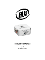
Figure 1 – MVII-DVI-TX
Transmitter Rear View
(Optional) Depending on installation requirements: At
any time during installation, the transmitter may be securely
mounted using appropriate brackets and hardware.
PRECAUTIONS: (1) Do not apply AC power until instructed to
do so. (2) This equipment is not intended for, nor does it
support, distribution through an Ethernet network. Do not
connect these devices to any sort of networking or
telecommunications equipment! (3) Use only tvONE-approved
MultiView™ power adapters. Failure to do so may damage this
device and will void the warranty.
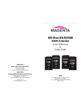
Figure 2 – MVII-DVI-TX
Transmitter Front View
Note: The DB9 serial port is
only available when the “SAP”
option is present.
Connect the F/UTP cable
via the LINK OUT port.
(Optional) Connect
local display via the
LOCAL OUT port.
Connect video source
to the transmitter’s
DVI IN port.
(Optional) Make your serial and/or audio connections
via the DB9 IOIO or AUX I/O connectors, as needed.
Connect the DC power cable (+5VDC @ 2.6A. max) to
the POWER port.
Power ON indicator
Video-status
indicator
Operating mode:
Off = normal, On = Config
Configuration
status indicators
Off = normal, On
= Config

© 2014 tvONE, 2791 Circleport Drive, Erlanger KY 41018 USA
Document # CSG-MULTIVIEW-TX Rev-06 (09/03/2015) Page 2 of 2
Sync-mode Options: The DVI-TX is factory-configured for Fixed-Sync mode. This is the required mode for compatibility with the
companion MVII-DVI-Rx-1K receiver which provides a DVI-D output signal. The DVI-TX is also compatible with other MultiView-II
analog receivers that provide a VGA output signal. For these analog receivers, RepliSync-II mode is preferred as it will offer the widest
range of compatibility with video formats. However, special circumstances may necessitate that one of the other sync-modes be
selected. In any case, all attached receivers must also be configured for the same sync-mode. Otherwise, you may not get a proper
video display output at that receiver.
(starting in normal-mode) Press and release the CFG button once to access configuration-mode. CFG indicator = on.
Press and release the SEL button once. You will now be able to change sync-mode settings.
LED indicators 1-3 should be illuminated (either DIM or ON); all others (indicators 4-8) should be off.
Press the CFG button repeatedly to step through the available sync-mode settings as shown below.
To leave configuration-mode step through all the options OR leave the buttons untouched for 10 seconds.
LED1
LED2
LED3
Front Panel View
Sync-mode Setting
dim
dim
dim
The DVI-TX will auto-detect the required RepliSync-I mode (“normal” or
“stretched”).
dim
dim
ON
Force RepliSync-I normal Horizontal sync. pulse encoding.
dim
ON
dim
Force RepliSync-I “stretched” Horizontal sync. pulse encoding.
dim
ON
ON
Force RepliSync-II.
ON
dim
dim
Force Fixed-Sync mode. This is the factory-default setting. This is the
required mode when interfacing to a MultiViewII DVI-Rx-1K receiver. NOTE: All
connected MultiView receivers must also be in fixed-sync mode and with legacy units requiring the
appropriate H/V polarities to be selected.
4
th
Pair Options: The DVI-TX provides several options for using the 4
th
-pair signals (pairs 1-3 are generally used for video). The
factory-default settings support analog audio (L+R summed) on the 4
th
-pair. Note that any connected MultiView receiver must be
configured with a matching 4
th
-pair operating mode. Otherwise, the desired 4
th
-pair signal will not work as expected. Note: If the
optional SAP daughterboard is installed then the 4
th
-pair options are fixed and unchangeable.
(starting in normal-mode) Press and release the CFG button once to access configuration-mode. CFG indicator = on.
Press and release the SEL button twice. You will now be able to change 4
th
-pair option settings.
LED indicators 4-6 should be illuminated (either DIM or ON); all others (indicators 1-3, 7 and 8) should be off.
Press the CFG button repeatedly to step through the available 4
th
-pair settings as shown below.
To leave configuration-mode step through all the options OR leave the buttons untouched for 10 seconds.
LED4
LED5
LED6
Front Panel View
4
th
-pair Operating Mode
Note: if an optional daughterboard is installed these cannot be changed.
dim
dim
dim
If SAP option-module is installed: 4
th
-pair operating mode is fixed to SAP mode
and this setting cannot be changed
If the SAP option-module is not installed: 4
th
-pair signals are disabled. This
effectively “mutes” anything being sent on the 4
th
pair. This can be useful for
diagnostic purposes.
dim
dim
ON
Direct pass-through of 4
th
-pair wires (custom applications).
dim
ON
dim
External analog (L+R summed) audio. This is the factory-default mode if no
daughterboard option is installed. (-A mode).
dim
ON
ON
External S/PDIF digital audio. Input-impedance = 75-ohms.
ON
dim
dim
Simplex-serial (“-S” mode).
ON
dim
ON
Internal S/PDIF digital audio, de-embedded from video stream.
To reset all user-configurable options back to factory-default settings:
Disconnect the DC power cable (or AC power).
Press and hold the CFG button.
Connect the DC power cable (or AC power). All LEDs blink 3 times – all settings are now changed back to factory-defaults.
Release the CFG button.
Troubleshooting: In many cases, problems encountered when installing MultiView™ II extension products can be resolved by
checking the F/UTP cable termination. It must be pinned out according to the TIA/EIA 568B standard wiring specification. For additional
troubleshooting information, or to obtain the TIA/EIA 568B wiring specifications please refer to the latest version of the MultiView™ II
DVI-TX User Guide, downloadable from www.tvone.com.
/