Page is loading ...

ENGLISH
Dometic Environmental Corporation
Rev. 20071204
L-2485
REMOTE AUXILIARY AIR CONDITIONING
AND AIR DISTRIBUTION SYSTEMS
FOR VOLVO L-5 CHASSIS
INSTALLATION GUIDELINES
For Volvo Truck Models VN 770, 780, 830, 880

COPYRIGHT © 2007 Dometic Corporation, All Rights Reserved.
No part of this publication may be reproduced, translated, stored in a retrieval system, or transmitted in any form or by any means electronic, mechanical,
photocopying, recording or otherwise without prior written consent by Dometic Environmental Corporation. Every precaution has been taken in the preparation of
this manual to insure its accuracy. However, Dometic Environmental Corporation assumes no responsibility for errors and omission. Neither is any liability assumed
for damages resulting from the use of this product and information contained herein.

ENGLISH
3
Volvo L-5 A/C - Air Distribution System
DOMETIC TRUCK REMOTE AUXILIARY AC SYSTEMS
FOR VOLVO L-5 CHASSIS
CONTENTS
INTRODUCTION 4
INSTALLING THE CONTROL 4
Required Tools 4
Installing the Qt Digital Display
4
Mounting the Power Logic Box
5
Routing Cables
6
INSTALLING THE RETURN AIR VENT 7
INSTALLING THE SUPPLY AIR DISTRIBUTION 7
Volvo Ductwork 7
Custom Air Distribution Plenum 1
0
Preparing for mounting the footwell and air plenum 1
0
Re-installing the Footwell 1
0
Installing the Plenum on the Front of the CHEB 1
4
INSTALLING THE CHEB 14
INSTALLING THE CONDENSER 17
ROUTING THE REFRIGERANT LINES AND CONDENSER POWER CABLE 18
TESTING THE INSTALLATION 20

ENGLISH
Volvo L-5 A/C - Air Distribution System
4
The instructions that follow represent years of development of parts and procedures
that make the system perform well and appear “factory-installed.”
INTRODUCTION
INSTALLING THE CONTROL
Mount the control in a place that provides the driver
convenient access. An ideal location would be near
the current HVAC controls.
Required Tools
• Drill motor
• Hole saws: 1-5/8", 1-7/8", 2-1/2", 3.5" (for 10K unit)
and 4"
• Drill bits: 1/8", 5/32", 9/32"
• Nut drivers: 1/4", 3/8", 15/16"
• Phillips head screwdriver
• Open-end wrenches: (2) 7/16", (1 each) 5/16", 13/16"
& 3/4"
• Torque wrench may be also be required
Figure 1. Typical Control Installation
Installing the Qt Digital Display
Refer to the mounting instructions and template
provided with your kit.
• Route the CXP cable through the wall and into the
luggage compartment. Remove the factory HVAC
control panel to do this.
• Route the CXP cable to the rear of the bunk for later
connection.

ENGLISH
5
Volvo L-5 A/C - Air Distribution System
Mounting the Power Logic Box
The Power Logic Box (PLB) will be mounted under
the rear, center portion of the bunk (see Figure 2). To
accomplish this, rst remove the carpeted panel at
the rear of the bunk. It is held in place by “Christmas
trees” at each corner.
Remove the backing plate from the PLB, by removing
the four machine screws at the bottom (see Figure 3).
Place the backing plate on the front of the bunk
center area, off center toward the passenger side.
Locate the two weldnuts, and place the backing plate
between them. Mark the four mounting holes, and
remove the plate.
Drill four diameter 7/32" holes. Use four #10 machine
screws to mount the box. The easiest way to do this
is to put the machine screws through the holes, and
secure with a nut. Replace the mounting plate onto
the PLB. Slide the PLB behind the bunk, and push
Figure 2. Mounting location for Power Logic Box

ENGLISH
Volvo L-5 A/C - Air Distribution System
6
onto the machine screws. Secure the box with four
nuts and lockwashers. KEPS nuts are easiest to use.
Routing Cables
The box has several different types of cables:
• Wires enclosed in split loom
• Flexible power cables
• “Phone” type cables
The “wires in split loom” will go toward the CHEB
unit.
Figure 3. Fastener location on Power Logic Box
The exible power cord(s) will go toward the power
distribution panel.
The phone cable mounted on the CHEB unit plugs
into the hole marked “TSEP.”
The phone cable from the control display plugs into
the hole marked “Display.”
For easier installation, it is recommended that the
cables be placed in the appropriate direction before
mounting the box. All cables should be neatly routed
and clipped, to prevent chafng.

ENGLISH
7
Volvo L-5 A/C - Air Distribution System
INSTALLING THE RETURN AIR
VENT
The supplied return air vent should be installed under
the bunk in the side panel, either on the passenger or
driver side. The passenger side is recommended as
there is less chance that it will get blocked by objects
in the luggage compartment, and it will also allow
easy access to the refrigerant tting.
To install, locate the area shown in Figure 4.
The grill should be installed between the panel
supports on the backside of the kickpanel. Locate
the supports and cut out for the grill. A holesaw and
reciprocating saw is recommended to cut out the
hole. If your kit contains the 12.5" x 5.5" grills instead
of the 10" x 10" grill, use a 4" holesaw to cut at least
two holes behind each grill. Use of the reciprocating
saw is optional for those grills.
Figure 4. Vent location
INSTALLING THE SUPPLY AIR
DISTRIBUTION
For this installation, a custom air plenum must be
installed, as well as the Volvo ductwork. A 4" duct
will feed the Volvo ductwork, and a 6" (for the 14k
system) or 4" (for the 10k system) will feed the custom
air plenum.
Volvo Ductwork
To feed the Volvo ductwork, remove the passenger
side window footwell and a section of the duct, as
shown in Figure 5 and 6.
The duct is secured from the top by “star” screws.
Below the bunk, there is a sensor which must be
removed. Access the sensor from the passenger
luggage door. Remove the duct from the truck, and
cut a 4" hole into it as shown in Figure 7 & 8.

ENGLISH
Volvo L-5 A/C - Air Distribution System
8
Figure 5. Location of installed ductwork
Figure 6. Footwell removed

ENGLISH
9
Volvo L-5 A/C - Air Distribution System
Figure 7. Removal of sensor.
Figure 8a. Four inch hole cut in Volvo duct. Figure 8b. Installation of grill and ducting.

ENGLISH
Volvo L-5 A/C - Air Distribution System
10
Locate the V4 RND BLACK 4" grill. Using two cable
ties, secure the vanes so that they will not turn. See
Figure 8a and 8b. Use a length of the supplied weather
stripping under the lip of the grill to prevent air from
leaking after installation. Install the grill from the inside
of the duct, with the vanes pointing upward. Push the
duct and grill back into the hole from which it came.
With assistance from outside the truck, reach into the
luggage compartment and push the length of 4" duct
and one hose clamp over the grill. Push the duct over
the grill until the grill is tight up against the duct, then
tighten the clamp. Replace the duct, and tighten the
screws.
Custom Air Distribution Plenum
Find the metal custom plenum and the passenger
side window footwell.
Locate the four (4) V4 RND BLACK grills and line up
on the window footwell to mark for hole cutting. See
Figure 10. Use a 4" holesaw to cut the holes.
Line the anges of the plenum with the weather strip-
ping. See Figure 9. Place the plenum on the back of
the footwell and secure with the 6-32 screws. Trim the
Figure 9. Installing the weatherstripping on the custom plenum.
carpet at the bottom of the plenum duct so that the
carpet will fold up.
Preparing for mounting the foot-
well and air plenum
Before the footwell is mounted back into the truck, the
cut out for the duct must be made to allow the duct
to extend below the bunk surface. Use the template,
as provided in Figure12a or 12b, to cut the hole. Use
a 1/8" bit to drill locator holes from under the bunk.
Go to the passenger side luggage door, and look up
to the rear corner of the bunk. See Figure 11. Find
the metal support that holds the bunk, and drill right
at the edge at the side of the truck, and towards the
rear of the truck.
Re-installing the Footwell
Gently insert the duct into the hole. Direct it down-
ward, while pushing the footwell toward the window.
Once it is all the way down, put the top ange of the
footwell behind the window fascia. Fasten the foot-
well to the wall and oor.

ENGLISH
11
Volvo L-5 A/C - Air Distribution System
Figure 10. Preparing to install grills in footwell cover.
Figure 11. Location of cut out for ductwork.

ENGLISH
Volvo L-5 A/C - Air Distribution System
12
Figure 12a. Template for 4" duct for 10K unit
0
5
.
3
2.00
Cut with 3.5"
holesaw
Cut with reciprocating
saw

ENGLISH
13
Volvo L-5 A/C - Air Distribution System
3.50
0
0
.
4
Drill with 4"
hole saw
Cut with reciprocating saw
Figure 12b. Template for 6" duct for 14K unit

ENGLISH
Volvo L-5 A/C - Air Distribution System
14
Installing the Plenum on the Front
of the CHEB
Using a ¼" nutdriver, remove the plastic 5" or 7" oval
hose adaptor. Find the 4"x 6" (or 4"x4") distribution
plenum. Install the weather stripping on the contact
surfaces and place over the hole on the unit. Reinstall
the screws into the new plenum.
INSTALLING THE CHEB
Install the CHEB on the passenger side of the truck.
Locate the CHEB template (supplied with the unit)
and position it with the “edge of the unit” 1-1½" from
the factory HVAC unit mounting foot. The “edge of the
unit” line with the notations for the quick connections
should be nearest the bunk wall. The line of the “edge
of the unit” should be approximately 5" from the bunk
wall.
Mark for the two quick connect holes 3½" off the
“edge of the unit” using the construction lines. Drill
through the rubber mat with a 2½" hole saw (DO NOT
DRILL THROUGH THE METAL). Then drill through the
metal with a 1-7/8" holesaw.
Drill the drain hole with a 1-5/8" hole saw.
Drill for mounting brackets for the CHEB using the
following recommnedations:
Figure 13. Supply Air Distribution Plenum.

ENGLISH
15
Volvo L-5 A/C - Air Distribution System
• One inboard on the CHEB at the corner nearest the
rear of the truck
• One on the front, outboard
• One on the outboard near the air distribution
plenum
• One on the front of the CHEB, inboard (near the
factory HVAC unit)
Use the “edge of unit” line to situate one of the moun-
ting brackets for hole marking. Be sure your bracket is
located in an area noted on the mounting template by
“XXXXX”. This notation provides locations available
for mounting.
Figure 14. CHEB installed in passenger luggage box.
Install the watertight grommets (gray) into the two
1-7/8" holes. Push in until they lock in the hole.
Insert the CHEB unit into the truck. Make sure that
the drain tting is lined up with the hole. Install the
brackets by using one ¼"-20 x 2½" bolt (provided)
and one small washer from the top. Secure under-
neath the truck with one large washer, and one nylok
nut. Snug all bolts, to the point where the bracket just
starts to bend, then stop.
Push the condenser fan cord down through one of
the gray grommets. Then insert the refrigerant lines
into their respective grommets. Lightly lubricate one
side of each coupling with light oil or refrigerant oil.

ENGLISH
Volvo L-5 A/C - Air Distribution System
16
Be sure to get the face and the threads. Hand tighten
the quick connect, making sure they thread correctly.
Tighten with the correct wrenches (13/16", ¾", and
15/16"). Tighten to 10-12 ft-lbs.
Note:
Any hissing that is heard during the tightening process,
is caused by the ttings that are not quite in line. DO
NOT STOP TIGHTENING. Keep tightening, and the
hissing will stop.
Connect the TSEP (temperature sensor cord located
on CHEB) to the PLB. Connect the electrical connec-
tors between the CHEB and PLB (the ones in the split
loom). Route and clip to prevent chang.
Connect the ductwork to the CHEB, use the hose
clamps to secure. It may be difcult to get the 6" duct
on, but it will connect. Use only as much duct as you
have to, as extra duct will impede air ow.
Install the 3/8" drain tting into the bottom of the
CHEB from the under side of the truck, nger tighten.
Place the hose clamp over the end of the P-trap.
Push the end of the P-trap over the drain tting, and
tighten clamp.
Figure 15. View of supply ducting connected.

ENGLISH
17
Volvo L-5 A/C - Air Distribution System
Figure 16. Condenser installed on mounting plate.
INSTALLING THE CONDENSER
The Dometic condenser may be installed either under
or behind the sleeper. These installations (and the
parts in the kit) are for an installation underneath the
sleeper. If you plan on mounting the generator and/or
generator radiator underneath the sleeper fairings, we
recommend mount the HVAC condenser on the rear
of the sleeper.
Mount the condenser to the mounting plate provi-
ded. The quick connects should be on the end of
the mounting plate with the side extension. Use the
nylok nuts provided and snug all bolts. This mounting
plate is specially designed to t under the Volvo L-5
chassis. It mounts midline of the truck, just behind
the transmission and in front of the exhaust pipe. The
“ngers” of the plate t up under a cab support. The
rear ange slips over another support. Mount with the
four stainless steel self-tapping screws provided.

ENGLISH
Volvo L-5 A/C - Air Distribution System
18
ROUTING THE REFRIGERANT
LINES AND CONDENSER POWER
CABLE
The refrigerant lines will pass over the exhaust pipe,
then over top of the condenser mounting plate, and
back around to the quick connect. Connect the quick
connects in the manner described previously. Secure
the refrigerant lines as shown, with one cushion clamp
on the mounting plate side extension, and one on the
opposite side to prevent movement and chang. Use
cable ties to secure the refrigerant lines to each other
and to the condenser power cable. After connecting
the condenser power cable, secure power cord in
such a manner that the connections are pulled in a
linear fashion, not to the side.
Install the heat shield as shown, using two 6" hose
clamps.
Figure 17. Routing of refrigerent lines.

ENGLISH
19
Volvo L-5 A/C - Air Distribution System
Figure 17. Heat shield installed.
Figure 18. Routing of refrigerent lines

ENGLISH
Volvo L-5 A/C - Air Distribution System
20
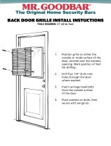
Figure 20. Routing of refrigerant lines.
TESTING THE INSTALLATION
Supply power to the power distribution panel with
either shorepower or generator power. Look at the
display panel and conrm that the display is lit up.
Press the FAN button to activate the fan in manual
mode. Check for airow from all vents. Next, press
the HEAT button and run the SETpoint up sufciently
for the unit to come on in heat mode. The HEATING
LED should illuminate. The air should start warming
up. To conrm heating quicker, manually lower the fan
speed ot the lowest setting.
Next, check the cooling mode. Press the COOL
button, then run the SETpoint down sufciently for the
unit to come on in the cool mode. The COOLING LED
should illuminate. The air should start cooling down.
Check to make sure the condenser fan is running. If
it is cool, it may take a few minutes for the condenser
fan to come on. This is normal. Shut down the unit by
pressing OFF. You are now nished with the installa-
tion.
/