
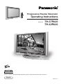
Progressive Plasma Television
Operating Instructions
TH-37PA20
TH-42PA20
Model No.
TQBC0627-3
Please read these instruction before operating your set and retain them for future reference.
English
1
2 3
4
5 6
7
C
8 9
0
Pedestal stand shown above is optional extra.

2
Dear Panasonic Customer
Welcome to the Panasonic family of customers. We hope that you will have many years of
enjoyment from your new Plasma TV.
To obtain maximum benefit from your set, please read these Instructions before
making any adjustments, and retain them for future reference.
Retain your purchase receipt also, and note down the model number and serial
number of your set in the space provided on the rear cover of these instructions.
Sales and Support Information
Customer Care Centre
•
For UK customers: 08705 357357
•
For Republic of Ireland customers: 01 289 8333
Direct Sales at Panasonic UK
•
Order accessory and consumable items for your
product with ease and confidence by phoning our
Customer Care Centre Monday - Friday 9:00am –
5:30pm. (Excluding public holidays).
•
Or go on line through our Internet Accessory ordering
application at www.panasonic.co.uk.
•
Most major credit and debit cards accepted.
•
Visit our website for product information
•
E-mail: customer[email protected]
•
All enquiries transactions and distribution facilities
are provided directly by Panasonic UK Ltd.
•
It couldn’t be simpler!
•
Also available through our Internet is direct shopping
for a wide range of finished products, take a browse
on our website for further details.

3
Table of Contents
Trademark Credits
•
VGA is a trademark of International Business Machines Corporation.
•
Macintosh is a registered trademark of Apple Computer, USA.
•
S-VGA is a registered trademark of the Video Electronics Standard Association.
Even if no special notation has been made of company or product trademarks, these trademarks have been fully
respected.
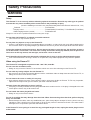
Symptoms
After-images appear
CAUTION:
Check
Do not allow a still picture to be displayed for an extended period, as this can
cause a permanent after-image to remain on the Plasma TV.
Examples of still pictures include logos, video games, computer images, teletext
and images displayed in 4:3 mode.
Note:
The permanent after-image on the Plasma TV resulting from fixed image use is
not an operating defect and as such is not covered by the Warranty.
This product is not designed to display fixed images for extended periods of time.
ABCDEF
ABCDEF
Important Safety Notice ............................................ 4
Safety Precautions .................................................... 5
Supplied Accessories ............................................... 7
Fitting remote control batteries ................................ 7
Quick start Guide ...................................................... 8
Choose Your Connection Type................................. 8
Cable fixing band ................................................... 11
Mains lead connection ........................................... 12
Plasma TV On/Off .................................................. 12
Auto setup .............................................................. 13
Basic controls ......................................................... 14
Front panel controls and Remote control ............... 14
VCR / DVD player Operation ................................. 15
Using the On Screen Displays ............................... 16
Q-Link ....................................................................... 18
Auto setup tuning ................................................... 19
Auto setup .............................................................. 19
Tuning menu ............................................................ 20
Manual Tuning ....................................................... 21
Decoder (AV2/AV4) ................................................ 22
Shipping condition .................................................. 22
Owner ID ................................................................ 23
Setup menu.............................................................. 24
Aspect Controls ...................................................... 26
Sound menu ............................................................ 28
Picture menu ........................................................... 30
Picture Adjustments (PC mode) ............................ 32
Advanced settings .................................................. 33
Adjusting Position and Size ................................... 34
Tuning your VCR and satellite receiver ................ 35
Tuning your TV to the VCR .................................... 35
Multi Window ........................................................... 36
Picture and text ...................................................... 36
Channel Search ....................................................... 37
Programme edit ....................................................... 38
TELETEXT Operation .............................................. 42
TELETEXT ............................................................. 42
Connections ............................................................ 44
How to connect the Input/Output terminals ............ 45
How to connect the AUDIO OUT terminals ............ 46
How to connect the Headphones / AV3 terminals .. 46
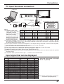
PC Input Terminals connection .............................. 47
Input signal that can be displayed .......................... 47
Troubleshooting ...................................................... 48
For your Guidance .................................................. 49
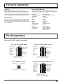
Pin Assignment ....................................................... 49
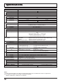
Specifications .......................................................... 50

4
WARNING
1) To prevent damage which may result in fire or shock hazard, do not expose this appliance to rain or
moisture.
Do not place containers with water (flower vase, cups, cosmetics, etc.) above the set. (including on
shelves above, etc.)
2) To prevent electric shock, do not remove cover. No user serviceable parts inside. Refer servicing to qualified
service personnel.
3) Do not remove the earthing pin on the mains plug. This apparatus is equipped with a three pin earthing-type
mains plug. This plug will only fit an earthing-type mains outlet. This is a safety feature. If you are unable to
insert the plug into the outlet, contact an electrician.
Do not defeat the purpose of the earthing plug.
Important Safety Notice
CAUTION
This appliance is intended for use in environments which are relatively free of electromagnetic fields.
Using this appliance near sources of strong electromagnetic fields or where electrical noise may overlap with the
input signals could cause the picture and sound to wobble or cause interference such as noise to appear.
To avoid the possibility of harm to this appliance, keep it away from sources of strong electromagnetic fields.
IMPORTANT: THE MOULDED PLUG
FOR YOUR SAFETY, PLEASE READ THE FOLLOWING TEXT CAREFULLY.
This appliance is supplied with a moulded three pin mains plug for your safety and convenience. A 5 amp fuse is fitted
in this plug. Shall the fuse need to be replaced, please ensure that the replacement fuse has a rating of 5 amps and
that it is approved by ASTA or BSI to BS1362.
Check for the ASTA mark
ASA
or the BSI mark
on the body of the fuse.
If the plug contains a removable fuse cover, you must ensure that it is refitted when the fuse is replaced.
If you lose the fuse cover the plug must not be used until a replacement cover is obtained.
A replacement fuse cover can be purchased from your local Panasonic Dealer.
If the fitted moulded plug is unsuitable for the socket outlet in your home, then the fuse shall be removed and
the plug cut off and disposed of safety. There is a danger of severe electrical shock if the cut off plug is
inserted into any 13 amp socket.
If a new plug is to be fitted, please observe the wiring code as shown below.
If in any doubt, please consult a qualified electrician.
WARNING: THIS APPARATUS MUST BE EARTHED.
IMPORTANT:
The wires in this mains lead are coloured in accordance with the following code:
Green-and-Yellow: Earth Blue: Neutral Brown: Live
As the colours of the wire in the mains lead of this appliance may not correspond with the coloured markings identifying
the terminals in your plug, proceed as follows.
The wire which is coloured GREEN-AND-YELLOW must be connected to the terminal in the plug which is marked
with the letter E or by the Earth symbol
or coloured GREEN or GREEN-AND-YELLOW.
The wire which is coloured BLUE must be connected to the terminal in the plug which
is marked with the letter N or coloured BLACK.
The wire which is coloured BROWN must be connected to the terminal in the plug
which is marked with the letter L or coloured RED.
How to replace the fuse. Open the fuse compartment with a screwdriver and replace the fuse.
To prevent electric shock, ensure the grounding pin on the mains plug is securely connected.

5
Safety Precautions
WARNING
Setup
This Plasma TV is for use only with the following optional accessories. Use with any other type of optional
accessories may cause instability which could result in the possibility of injury.
(All of the following accessories are manufactured by Matsushita Electric Industrial Co., Ltd.)
•
Pedestal ......................................................... TY-ST42PA20
•
Display stand ................................................. TY-S42PA20W (TH-42PA20), TY-S37PA20W (TH-37PA20)
•
Wall-hanging bracket (vertical) ...................... TY-WK42PV2W
Always be sure to ask a qualified technician to carry out set-up.
Do not place the Plasma TV on sloped or unstable surfaces.
•
The Plasma TV may fall off or tip over.
Do not place any objects on top of the Plasma TV.
•
If water is spilt onto the Plasma TV or foreign objects get inside it, a short-circuit may occur which could result in
fire or electric shock. If any foreign objects get inside the Plasma TV, please consult your local Panasonic dealer.
If using the pedestal (optional accessory), leave a space of at least 10 cm at the top, left and right, at least 6
cm at the bottom, and at least 7 cm at the rear. If using some other setting-up method, leave a space of at
least 10 cm at the top, bottom, left and right, and at least 1.9 cm at the rear.
Avoid installing this product near electronic equipment that is easy to receive electromagnetic waves.
•
It will cause interference in image, sound, etc. In particular, keep video equipment away from this product.
When using the Plasma TV
The Plasma TV is designed to operate on 220 - 240 V AC, 50/60 Hz.
Do not cover the ventilation holes.
•
Doing so may cause the Plasma TV to overheat, which can cause fire or damage to the Plasma TV.
Do not stick any foreign objects into the Plasma TV.
•
Do not insert any metal or flammable objects into the ventilations holes or drop them onto the Plasma TV, as
doing so can cause fire or electric shock.
Do not remove the cover or modify it in any way.
•
High voltages which can cause severe electric shocks are present inside the Plasma TV. For any inspection,
adjustment and repair work, please contact your local Panasonic dealer.
Securely insert the mains plug as far as it will go.
•
If the plug is not fully inserted, heat may be generated which could cause fire. If the plug is damaged or the wall
socket plate is loose, they shall not be used.
Do not handle the mains plug with wet hands.
•
Doing so may cause electric shocks.
Do not do anything that may damage the mains lead. When disconnecting the mains lead, pull on the plug
body, not the cable.
•
Do not damage the cable, make any modifications to it, place heavy objects on top of it, heat it, place it near any
hot objects, twist it, bend it excessively or pull it. To do so may cause fire and electric shock. If the mains lead is
damaged, have it repaired at your local Panasonic dealer.
If the Plasma TV is not going to be used for any prolonged length of time, unplug the mains plug from the
mains outlet.

6
Safety Precautions
If problems occur during use
If a problem occurs (such as no picture or no sound), or if smoke or an abnormal odour starts to come out
from the Plasma TV, immediately unplug the mains plug from the mains outlet.
•
If you continue to use the Plasma TV in this condition, fire or electric shock could result. After checking that the
smoke has stopped, contact your local Panasonic dealer so that the necessary repairs can be made. Repairing
the Plasma TV yourself is extremely dangerous, and should never be attempted.
If water or foreign objects get inside the Plasma TV, if the Plasma TV is dropped, or if the cabinet becomes
damages, disconnect the mains plug immediately.
•
A short circuit may occur, which could cause fire. Contact your local Panasonic dealer for any repairs that need to
be made.
CAUTION
When using the Plasma TV
Do not bring your hands, face or objects close to the ventilation holes of the Plasma TV.
•
Heated air comes out from the ventilation holes at the top of Plasma TV will be hot. Do not bring your hands or
face, or objects which cannot withstand heat, close to this port, otherwise burns or deformation could result.
Be sure to disconnect all cables before moving the Plasma TV.
•
If the Plasma TV is moved while some of the cables are still connected, the cables may become damaged, and fire
or electric shock could result.
Disconnect the mains plug from the mains socket as a safety precaution before carrying out any cleaning.
•
Electric shocks can result if this is not done.
Clean the mains lead regularly to prevent it becoming dusty.
•
If dust built up on the mains lead, the resultant humidity can damage the insulation, which could result in fire. Pull
the mains plug out from the mains outlet and wipe the mains lead with a dry cloth.
This Plasma TV radiates infrared rays, therefore it may affect other infrared communication equipment.
Install your infrared sensor in a place away from direct or reflected light from your Plasma TV.
Cleaning and maintenance
The front of the display panel has been specially treated. Wipe the panel surface gently using only a cleaning
cloth or a soft, lint-free cloth.
•
If the surface is particularly dirty, wipe with a soft, lint-free cloth which has been soaked in pure water or water to
which a small amount of neutral detergent has been added, and then wipe it evenly with a dry cloth of the same
type until the surface is dry.
•
Do not scratch or hit the surface of the panel with fingernails or other hard objects, otherwise the surface may
become damaged. Furthermore, avoid contact with volatile substances such as insect sprays, solvents and thinner,
otherwise the quality of the surface may be adversely affected.
If the cabinet becomes dirty, wipe it with a soft, dry cloth.
•
If the cabinet is particularly dirty, soak the cloth in water to which a small amount of neutral detergent has been
added and then wring the cloth dry. Use this cloth to wipe the cabinet, and then wipe it dry with a dry cloth.
•
Do not allow any detergent to come into direct contact with the surface of the Plasma TV.
If water droplets get inside the unit, operating problems may result.
•
Avoid contact with volatile substances such as insect sprays, solvents and thinner, otherwise the quality of the
cabinet surface may be adversely affected or the coating may peel off. Furthermore, do not leave it for long
periods in contact with articles made from rubber or PVC.

7
1
2 3
4
5 6
7
C
8 9
0
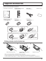
Supplied Accessories
Check the accessories before installations.
Slide off the battery cover Insert batteries - note correct
polarity (+ and -)
Replace the cover
Fitting remote control batteries
123
• Make sure that the batteries are fitted the correct way round.
• Do not mix old batteries with new batteries. Remove old, exhausted batteries immediately.
• Do not mix different battery types, i.e. Alkaline and Manganese or use rechargeable (Ni - Cad) batteries.
Two “R6 (UM3)” size
•
Operating Instruction book
•
Remote Control Transmitter
(N2QAJB000081)
•
Mains lead
K2CT3DH00017
•
Batteries for the Remote
Control Transmitter
(2 × R6 (UM3) size)
•
Warranty Card
•
Ferrite core
J0KG00000018 × 5
(small size)
•
Ferrite core
J0KG00000054 × 3
(large size)
Installing the ferrite core (Small size)
Pull back the tabs
(in two places)
Open
Press the cable
through and close
1
2
3
Installing the ferrite core (Large size)
Pull back the tabs
(in two places)
Open
Press the cable
through and close
1
2
3
(See page 46 for details)
(See page 47 for details)

8
Quick start Guide
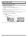
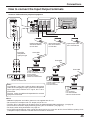
Choose Your Connection Type
Connection and setting up options
• If connecting the TV using an RF cable only, see below.
• If connecting the TV using Scart and RF cables, see page 9.
• If connecting the TV to a Q-Link (or Q-Link compatible) VCR, see page 9.
• If connecting the TV to a Q-Link (or Q-Link compatible) VCR and a satellite receiver, see page 10.
What is Q-Link?
Q-Link allows direct communication between the TV and a Q-Link (or Q-Link compatible) VCR, this will enable
features such as downloading of tuning information from the TV to the VCR.
Further information on Q-Link can be found on page 18.
In order for Q-Link to function correctly, the Scart cables must be connected as shown in connection diagram,
dependent on whether the TV is being connected to a VCR or to a VCR and Satellite Receiver.
1. Connecting the TV directly to an ANTENNA only
ANTENNA
Antenna Lead
Plasma TV
R
RGB
VIDEO
S VIDEO VIDEO S VIDEO
L
P
R
P
B
Y
AUDIO OUT
AV 4C
AV4 AV2 AV1
COMPONENT
VIDEO
VIDEO RGB
RF connection
Connect the Aerial lead into the TV Aerial socket ( ).
Note: Additional equipment and cables shown are not supplied with this set.

9
Quick start Guide
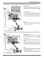
3. Q-Link connection of Plasma TV and VCR/DVD recorder using Scart and RF cables
RF connection
Connect the ANTENNA to the Antenna Input terminal
of the VCR and an RF cable from the VCR Antenna
Output terminal to this set Antenna Input terminal ( ).
Scart Connections
The VCR can also be connected to this set using a
Scart cable if you are using a Scart equipped VCR.
• Use this set’s AV1 Scart socket for a VCR.
• Use this set’s AV2 Scart socket for an S Video VCR.
• Use this set’s AV4 Scart socket for an S Video VCR.
Notes:
• Additional equipment and cables are not supplied.
• Further details of audio / video connections can be
found on pages 45 and 46.
2. Connection of Plasma TV and VCR/DVD recorder using Scart and RF cables
RF connection
Connect the ANTENNA to the Antenna Input terminal
of the VCR and an RF cable from the VCR Antenna
Output terminal to this set Antenna Input terminal ( ).
Scart connection
The VCR must be connected to the AV2/AV4 Scart
socket of this set using a ‘fully wired’ Scart cable.
Note:
If using a ‘Q-Link’ VCR then the AV1 Scart socket of
the VCR must be connected to the AV2/AV4 Scart
socket of this set. If your VCR is not a ‘Q-Link’ VCR,
please consult your VCR operating instruction book.
Notes:
• Additional equipment and cables are not supplied.
• Further details of audio/ video connections can be
found on page 45 and 46.
• Further information for VCR and Satellite Receiver
installation with this set can be found on page 10.
R
RGB
VIDEO
S VIDEO VIDEO S VIDEO
L
P
R
P
B
Y
AUDIO OUT
AV 4C
AV4 AV2 AV1
COMPONENT
VIDEO
VIDEO RGB
AV1/AV2/AV4
Scart sockets
VCR/DVD recorder
ANTENNA
Antenna Lead
Antenna
Output terminal
Antenna
Input terminal
Antenna
Input terminal
AV1
Scart socket
Plasma TV
AV2/AV4
Scart sockets
R
RGB
VIDEO
S VIDEO VIDEO S VIDEO
L
P
R
P
B
Y
AUDIO OUT
AV 4C
AV4 AV2 AV1
COMPONENT
VIDEO
VIDEO RGB
ANTENNA
Antenna Lead
Antenna
Output terminal
Antenna Input terminal
Antenna
Input terminal
AV1
Scart socket
VCR/DVD recorder

10
Quick start Guide
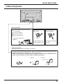
4. Q-Link connection of Plasma TV, VCR/DVD recorder and Satellite Receiver using Scart
and RF cables
For Q-Link to function correctly this set, VCR and
Satellite Receiver must be connected as shown in
the diagram below.
RF connections
• Connect an RF cable to the Antenna Input terminal
of the Satellite Receiver.
• Connect an RF cable from the Antenna Output
terminal of the Satellite Receiver to the Antenna
Input terminal of the VCR.
• Connect an RF cable from the Antenna Output
terminal of the VCR to this set Antenna Input
terminal ( ).
Scart connections
‘Fully wired’ Scart Cables should be used for all of
the Scart connections.
• The AV2 Scart socket of the VCR must be
connected to the VCR Scart socket of the Satellite
Receiver.
• The TV Scart socket of the Satellite Receiver must
be connected to the AV1 Scart socket of this set.
Note:
If using a ‘Q-Link’ VCR then the AV1 Scart socket
of the VCR must be connected to the AV2/AV4 Scart
socket of this set. If your VCR is not a ‘Q-Link’ VCR,
please consult your VCR operating instruction book.
Notes:
• Additional equipment and cables are not supplied.
• Further details of audio/ video connections can
be found on pages 45 and 46.
R
RGB
VIDEO
S VIDEO VIDEO S VIDEO
L
P
R
P
B
Y
AUDIO OUT
AV 4C
AV4 AV2 AV1
COMPONENT
VIDEO
VIDEO RGB
ANTENNA
Plasma TV
Antenna Lead
Antenna
Output terminal
Antenna
Input
terminal
Antenna
Input terminal
Antenna Input
terminal
Satellite
Receiver
TV
Scart
socket
VCR
Scart
socket
AV2
Scart
socket
AV1
Scart
socket
Antenna Output
terminal
AV1
Scart socket
AV2/AV4
Scart socket
VCR/DVD
recorder

11
Cable fixing band
– Cable fixing bands
Secure any excess cables with bands as required.
To secure cables connected to Terminals, wrap the cable fixing band around them then pass the
pointed end through the locking block, as shown in the figure.
While ensuring there is sufficient slack in cables to minimize stress (especially in the
power cord), firmly bind all cables with the supplied fixing band.
To tighten: To loosen:
Pull
Pull
Push the catch
– Mains lead fixing
1
Connect power plug to the socket of
the main body.
2
Fix the left clamper.
3
Fix the right clamper.
4
Install the ferrite core.
Ferrite core (Large size)
supplied.
How to fix:
Fix by pushing in till a
clicking sound is heard.
How to release:
Pull up while drawing
the knob.
Quick start Guide

12
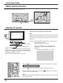
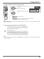
Plasma TV On/Off
Mains lead connection
Connect the AC cord plug to the Plasma TV.
TV/AV
F.P.
INDEX HOLD
PICTURE
SOUND
SET UP
TV/TEXT
DIRECT
TV REC
CH SEACH
STILL
Connect the mains plug to the mains Outlet
Note:
Mains plug types vary between countries. The mains plug
shown at left may, therefore, not be the type fitted to your set.
Press the On / Off switch on the Plasma TV to turn the set on:
Power-On.
Example: The screen below is displayed for a while after the
Plasma TV is turned on.
(setting condition is an example.)
From the second time on, the below screen is
displayed for a while (setting condition is an
example).
Press the
button on the remote control to turn the Plasma TV to standby.
Power Indicator: Red (standby)
Press the
button on the remote control to turn the Plasma TV on.
Turn the Plasma TV set off by pressing the
switch on the Plasma TV
while it is on or in standby mode.
Remote Control Sensor
Power Indicator
C.A.T.S sensor
Plasma C.A.T.S (Contrast Automatic Tracking System)
Plasma C.A.T.S automatically senses the ambient light
conditions and adjusts the brightness and gradation
accordingly, to optimise contrast.
(Effective when Viewing mode is set to Auto.)
1
For VIDEO / COMPONENT / TV INPUT:
Note:
The unit will still consume some power as long as the mains lead is still inserted
into the mains outlet.
Quick start Guide

13
Quick start Guide
Notes:
If the recording device has not accepted download data from the TV, you may need to select the Download option from
the device’s menu system.
Refer to the recording device’s operating instruction book.
If Q-Link is not operating correctly, check the following:
• The Scart cable is connected to the TV’s correct Scart socket.
• The Scart cable is connected to the VCR’s compatible (Q-Link, NEXTVIEWLINK or similar technology) Scart socket.
• The Scart cable is a “fully wired” type.
For further information on Q-Link and connecting equipment, see pages 18 and 45.
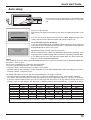
• The sorted programme order depends upon the TV signal, the broadcasting system, and reception conditions.
If the order is not to your preference it can be rearranged. Refer to the Programme edit menu - see page 17 for details.
•
If you have a digital satellite receiver, you can start Auto setup with the receiver set to any channel. You will then have to
manually name the ‘SAT’ position after Auto setup is complete. Refer to the Programme edit - see page 38 for details.
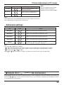
Prog. Position All channels No CH5
No CH5/S4C No CH4/CH5
No S4C No CH4/S4C No CH4/S4C/CH5
1 BBC1 BBC1 BBC1 BBC1 BBC1 BBC1 BBC1
2 BBC2 BBC2 BBC2 BBC2 BBC2 BBC2 BBC2
3 ITV ITV ITV ITV ITV ITV ITV
4 CH4 CH4 CH4 S4C CH4 CH5 SAT
5 S4C S4C SAT SAT CH5 SAT ∗
6 CH5 SAT ∗∗SAT ∗
7SAT∗∗∗∗∗ ∗
Note:
∗ The next available channel will appear, if no other stations are available then the Programme position will remain unused.
TV/AV : To exit
21 68
AUTO SETUP IN PROGRESS
SEARCHING:PLEASE WAIT
DOWNLOAD IN PROGRESS
PLEASE WAIT
Programme : 11
Remote control unavailable
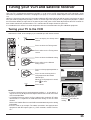
First, ensure that the recording device is in Standby mode,
if it has Q-Link function and Satellite receiver is switched
ON.
Plug in TV and switch on.
Programmes will appear immediately if your dealer has programmed the TV for
you.
If the TV has not been programmed for you then Auto setup will begin, your
stations will be located, sorted into order and stored ready for use.
TV to VCR /DVD recorder download
If a Q-Link, NEXTVIEWLINK or compatible recording device has been connected
to the correct Scart socket before starting Step 1 , programme information will
be downloaded to the device via Q-Link.
Downloaded tuning data will match the television’s.
Not all recording devices support this download of programme information, some
may require to be started manually. Refer to the device’s operating instruction book.
lf a recording device other than those described above has been connected,
then there will be no download operation.
Auto setup

14
S VIDEO
R - STANDBY
G - POWER ON
STR F TV/AV
AV3
VIDEO L R/ /
STR F TV/AV/ /
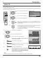
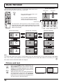
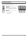
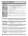
Basic controls
Front panel controls and Remote control
Picture Menu (see page 30, 31)
Sound Menu (see page 28, 29)
Setup Menu (see page 24, 25)
Ambience sound On or Off
(see page 29)
Aspect Control (see page 26, 27)
Direct TV Record button (see page 18)
Function selection
Displays the On Screen Display
functions, press repeatedly to
select from the available
functions.
The following adjustments can
be accessed directly.
Volume Up (+), Down (-)/
Programme Number Up ( ), Down ( )
Volume adjustment which uses these buttons is performed after
pressing Function button.
When programme number up ( ) or down ( ) button on the
front panel of the Plasma TV is pressed in stand-by mode,
the Plasma TV will be turned on.
TV/AVmode Selection
Press to select TV, AV input signal modes
sequentially.
AB
A
B
A
B
MULTI
WINDOW
MULTI WINDOW
Press to display main picture and sub picture (see page 36).
The main picture and sub picture can be changed by using Red, Green, Yellow and Blue buttons.
[Picture out of Picture]
main picture sub picture
[Picture and Picture] [Picture in Picture]
Normal
Viewing
main picture sub picture main picture sub picture
MULTI
WINDOW
Volume
Contrast
Brightness
Colour
Sharpness
Tuning mode
Balance
Treble
Bass
Tint
N (Normalise) button
Resets all settings to their default levels.
• Direct channel access
You can tune to TV channel directly by pressing the
“C” button and corresponding channel number
buttons.
Channel Number 36.....
C
,
3
,
6
• Direct Programme Number Selection
You can select the number directly by pressing “Num-
ber 0-9” buttons or by pressing “Two Digit” and “Num-
ber 0-9” buttons.
Programme Number 8 .....
8
Programme Number 12..... ,
1
,
2
When in standby mode, switches TV on.
Notes:
• Tint : In NTSC mode
• Tuning mode : Not displayed during AV mode.
Plasma TV ON / Off Switch
Store
(see page 20-23, 35, 39-41, 43)
Status button
Press to display programme position,
programme name, channel number, time, MPX
mode, Aspect mode, receiving system and
programme table.

15
N
DVD
REC
-
VCR
STR
PROGRAMME
TV/AV
1 2 3
4 5 6
7 8 9
F.P.
INDEX HOLD
CH SEACH
STILL
PICTURE
SOUND
SET UP
TV/TEXT
ASPECT
C
0
VCR
MULTI
WINDOW
DIRECT
TV REC
Basic controls
Plasma TV (Stand-by)
The TV set must first be plugged into the mains outlet and
turned on at the On / Off switch.
Press this button to turn the TV set On from Standby mode,
Press it again to turn the TV set to Standby mode.
Note:
It is also possible to turn the TV set on from
STANDBY mode by pressing the “Direct
Programme Number Selection” Buttons (0-9) on
the Remote Control.
Sound Mute
Press to mute the sound completely the “Mute” symbol will appear.
Press again to restore the previous sound level, and cancel the mute.
Programme Number Selection
Press to select the next higher or lower Programme number.
Volume Adjustment
Press to increase or decrease the sound volume level.
Volume
TV/AV Mode Selection
Press to select TV, AV input signal modes sequentially.
STILL
Press to freeze the picture, press again to return to watching the current
programme.
Coloured buttons used for
•
Programme edit
(see page 38-41)
• Teletext functions (see page 42-44)
• AV Selection
• Multi Window (see page 36)
• Channel Search (see page 37)
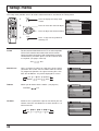
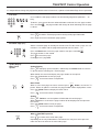
Basic controls
VCR / DVD player Operation
The Remote Control is capable of operating some functions of selected
Panasonic VCR’s and DVD (Digital Versatile Disc) player equipment. Some
VCR and DVD equipment have different functions, so to ensure compatibility
please refer to the equipment's instruction book or consult your dealer for
details.
Function
Standby
Press to switch the VCR or DVD to standby mode.
Press again to switch back on.
Pause / Still (VCR only)
Press in playback mode, the picture will pause.
Press again to restart play.
Programme Up / Down (VCR only)
Press to increase or decrease the VCR programme position by
one.
VCR / DVD switch
Use this switch to select whether controls operate DVD
equipment or your VCR.
Play
Press to playback the tape or DVD.
Stop
Press to stop the tape or DVD.
Record (VCR only)
Press this button to start recording.
Skip / Fast Forward / Cue
VCR: Press to fast forward the tape. In Play mode, press to view
the picture rapidly forward (Cue).
DVD: Press once to skip to the next track.
Skip / Rewind / Review
VCR: Press to rewind the tape. In Play mode, press to view the
picture rapidly in reverse (Review).
DVD: Press once to skip to the previous track.
Button
PROGRAMME
TELETEXT Operation
(see page 42-44)
Channel Search
(see page 37)
Store
(see page 20-23, 35, 39-41, 43)
Stores some settings in TUNING
menus and TELETEXT.

16
N
DVD
REC
-
VCR
STR
PROGRAMME
TV/AV
1 2 3
4 5 6
7 8 9
F.P.
INDEX HOLD
CH SEACH
STILL
PICTURE
SOUND
SET UP
TV/TEXT
ASPECT
C
0
VCR
MULTI
WINDOW
DIRECT
TV REC
This Help box indicates which buttons
on the remote control are used to
navigate the menu shown, see above for
descriptions of button functions.
An On Screen Help box is displayed
whenever a menu is displayed on the TV.
1 :
-
Off
2 : Off
3 : Off
4 : Off
5 : Off
Prog. Chan. Name Lock
Programme edit
TV/AV
’STR’ Button Store
Exit
Select
Option
Change
Programme
Return
Delete Add Move
TV
-
>
VCR
ON SCREEN HELP
‘Instruction’ box
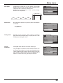
Please refer to the On Screen Help
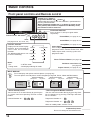
Using the On Screen Displays
Many features available on this set can be accessed via the On Screen Display menu system.
Use the remote control as shown below to access and adjust features as desired.
Contrast
Viewing mode
Brightness
Colour
Sharpness
P-NR
Colour balance
Picture menu
Normal
Dynamic
Off
3D-COMB
Off
Bass
Treble
Headphone volume
NICAM
Mode
Ambience
Volume
Balance
Sound menu
No service
Music
Off
Tuning menu
Q-Link
AV2
Side panel
Off
Access
Power save
Off
Off timer
Off
Tele t e xt
FASTEXT
AV2 out TV
Setup menu
Press to display “Picture menu”
screen. (see page 30)
Press to display “Sound menu”
screen. (see page 28)
Press to display “Setup menu”
screen. (see page 24, 25)
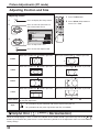
Normal
Setup
Normalise
H-Pos
H-Size
V-Pos
V-Size
Clock Phase
Sync
H & V
During “PC” input signal
(see page 34)
During “PC” input signal
Picture
Normalise
Picture Mode
Brightness
Sharpness
Normal
0
0
White balance
Normal
Advanced settings
On
Contrast
25
Normal
Normal
Advanced settings
Normalise
W/B High R
W/B High B
0
0
0
0
W/B Low R
Gamma
2. 2
0
W/B Low B
Press to select
“On”.
Press to enter
Advanced settings.
To Advanced settings
(see page 33)
To Picture adjust menu
(see page 32, 33)

17
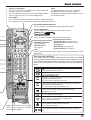
Press to move the cursor up and down on the menu.
Press to access menus, adjust levels or to select from a range of options.
The STR button is used with a number of features to store settings after
adjustments have been made or options have been set.
The TV/AV button is used to exit the menu system and return to the
normal viewing screen.
SETUP : Return to tuning menu
TV/AV : To exit
21 68
AUTO SETUP IN PROGRESS
SEARCHING:PLEASE WAIT
All current tuning
data will be erased
WARNING
STR : Start Auto setup
TV/AV : To exit
SETUP : Return to tuning menu
1 :
-
Off
2 : Off
3 : Off
4 : Off
5 : Off
Prog. Chan. Name Lock
Programme edit
TV/AV
’STR’ Button Store
Exit
Select
Option
Change
Programme
Return
Delete Add Move
TV->VCR
21 68
Manual tuning
TV/AV
’STR’ Button Store
Exit
Serch
down / up
Programme
down / up
Return
Programme edit
(see page 38-41)
Auto setup
(see page 19)
Manual turning
(see page 21)
Programme edit
Auto setup
Manual tuning
Tuning menu
Access
Access
Access
Access
Access
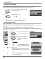
Decoder (AV2)
Shipping Condition
Owner ID
Off
Using the On Screen Displays
STR
TV/AV
N
1 2 3
4 5 6
7 8 9
0
C
STR : Start
TV/AV : To exit
SETUP : Return to tuning menu
All tuning data will be erased
Shipping condition
Shipping condition
(see page 22)
Tuning menu
(see page 19, 20-23, 38-41)
Input selection can be made by colour buttons, which match on screen button indication.
Colour buttons (Red, Green, Yellow, Blue)
AV1 AV2/S AV3/S/PC
AV4/S/C
PC
16 : 9
AV4 input: Composite or RGB (Controlled by external source)
S Video Component
TV/AV
1 2 3
4 5 6
7 8 9
F. P.
INDEX HOLD
PICTURE
SOUND
SET UP
TV/TEXT
ASPECT
MULTI
DIRECT
TV REC
CH SEACH
STILL
AV3 input: Composite S Video PC
AV2 input: Composite S Video
AV1 input: Composite or RGB (Controlled by external source)
Input signal selection by colour button

18
TV/AV
1 2 3
4 5 6
F. P.
INDEX HOLD
PICTURE
SOUND
SET UP
TV/TEXT
DIRECT
TV REC
CH SEACH
STILL
Preset Download
This allows the programme order from the TV to be downloaded to the recording device, helping to ensure that correct
recordings are made; there are several ways to perform this operation :
1. During installation as explained in the ’Quick Start Guide’ beginning on page 8-13.
2. When Auto setup is started from within the Tuning menu, see page 20.
3. Preset download started from the recording device, refer to the device’s operating instruction book.
Important Note:
Not all recording devices support this type of data communication system. Some may support certain features, but not
others. Refer to the recording device’s operating instruction book.
If Q-Link is inoperative, first confirm that your Scart cable is a “fully wired” type. Ask your dealer for further details.
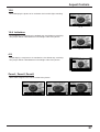
What You See Is What You Record (DIRECT TV RECORDING)
This will allow the immediate recording of the programme currently shown on the television, by
the recording device attached to the Scart socket, which can be chosen using “Q-Link”. (see
page 24).
Press the DIRECT TV REC button on the remote control.
If the recording device is in Standby mode with usable recording media inserted, it will automatically
switch on when you press the DIRECT TV REC button.
If a “Q-Link” device is connected, a message will appear on the TV screen showing what is being
recorded, or if it is not possible to record. Some “Q-Link” compatible devices will only display the
message when on the VCR programme position(0) or in AV mode. Refer to the device’s operating
instruction book.
When using a “NEXTVIEWLINK” device the main features possible are the following :
No recording -Check tape or discRecording in progress
The recording device is recording the programme signal
from its own tuner. If you wish you can switch off the TV
and leave the device recording in the normal way.
The tape or disc may have been “write protected”, missing
or may be damaged. The device may already be recording.
Refer to the device’s operating instruction book.
Additionally, when using a “Q-Link” device themain features possible are the following :
The following features are only available from the device connected to the scart socket selected using “Q-Link”. (see page 24).
TV / Recording device Auto Power On
If you insert pre-recorded media into the recording device and press the Play button whilst the TV is in ’Standby’ mode,
the TV will automatically switch on and select the correct AV input so that you can view the content.
Recording device Auto Power Standby
When the TV is switched into ’Standby’ mode, the recording device will also switch into ’Standby’ mode if there is no
media inserted, or if there is media inserted and the device is in ’Rewind’ or ’Stop’ mode. If a VCR is rewinding a tape,
it will not switch into ’Standby’ mode until rewinding has finished.
Recording device Image View On
If the TV is in Standby mode and the recording device sends a menu to be displayed on the TV screen (e.g. Main
menu), the TV will automatically switch On and the menu will be displayed.
Some other devices may support this feature. Refer to the device’s operating instruction book.
Important Note:
These recording devices may support some or all of the above functions. Refer to the device’s operating instruction book.
Not all recording devices support this type of data communication system. Somemay support certain features, but not
others. Refer to the device’s operating instruction book. Some features are only available from the device connected
to the scart socket selected using “Q-Link”. (see page 24).
If Q-Link is inoperative, first confirm that your Scart cable is a “fully wired” type. Ask your dealer for further details.
This TV will also communicate with other recording device’s that bear the following logos :
• “DATA LOGIC” (a trademark of Metz Corporation)
• “Easy Link” (a trademark of Philips Corporation)
• “Megalogic” (a trademark of Grundig Corporation)
• “SMARTLINK” (a trademark of Sony Corporation)
Q-Link
Q-Link allows the television to communicate with a compatible VCR or DVD Recorder.
For Q-Link communication to work, the TV must be connected to a recording device with the “Q-Link”, “NEXTVIEWLINK”,
“DATA LOGIC”, “Easy Link”, “Megalogic” or “SMARTLINK” logo using a “fully wired” Scart cable between the AV2
socket of the television and the appropriate socket on your VCR, and the AV4 socket of the television and the appropriate
socket on your DVD Recorder.
For connection to the appropriate Scart socket on the recording device, refer to the device’s operating instruction book.

19
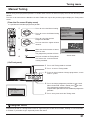
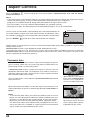
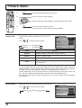
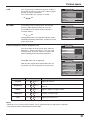
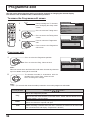
2 Press to start Auto setup tuning, then the Searching
screen will be displayed.
When Searching is complete the screen will return
to the Turning menu screen.
The best tuning position is automatically memorized.
Once this operation is completed the TV will display
programme position 1.
3 Press to exit from the Tuning Menu.
This returns the set to the normal viewing condition.
Display the Tuning menu screen
1 Open the setup menu.
2 Move to Tuning menu.
Access Tuning menu.
Auto setup tuning
1 Move to Auto setup.
Access Auto setup.
Auto setup tuning
Auto setup
Automatically scans all TV channels and stores them in memory.
Auto setup automatically retunes your set. This feature is useful, if for example, you move house and wish to retune
your set to receive the local stations.
Tuning menu
Q-Link
Side panel
Off
Power save
Off
Off timer
Off
Tele t e xt
FASTEXT
AV2 out TV
Setup menu
AV2
Access
Programme edit
Auto setup
Manual tuning
Tuning menu
Access
Decoder (AV2)
Shipping Condition
Owner ID
All current tuning
data will be erased
WARNING
STR : Start Auto setup
TV/AV : To exit
SETUP : Return to tuning menu
SETUP : Return to tuning menu
TV/AV : To exit
21 68
AUTO SETUP IN PROGRESS
SEARCHING:PLEASE WAIT
1 2 3
4 5 6
7 8 9
0
C
SET UP
Note:
If an auto setup process is aborted midway, all channels that have been set up to that point will be saved to memory.
Note:
If you proceed with the next step all tuning data will be erased (all stations
and their programme positions stored in your set’s memory will be wiped
out so the new settings can be stored).
STR
TV/AV

20
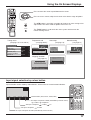
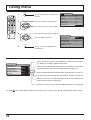
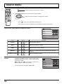
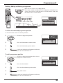
1 Press to display the Setup menu
screen.
2 Press to select the Tuning menu.
Press to Access the Tuning menu.
3 Press to select the menu to adjust.
Press to adjust or Access.
4 Press at any time to go back to
watching TV.
1 2 3
4 5 6
7 8 9
0
C
Tuning menu
Tuning menu
Q-Link
Side panel
Off
Power save
Off
Off timer
Off
Tele t e xt
FASTEXT
AV2 out TV
Setup menu
AV2
Access
Manual tuning
Programme edit
Auto setup
Access
Tuning menu
Decoder (AV2)
Shipping Condition
Owner ID
Off
TV/AV
Pressing
STR
after having adjusted some feature will store the setting as the default (replacing the factory setting).
Programme edit
Auto setup
Manual tuning
Tuning menu
Access
Access
Decoder (AV2)
Shipping Condition
Owner ID
Off
Access
Access
Access
SET UP
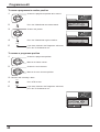
Access in order to customise your programme settings (see page 38-41).
(eg: adding or deleting a programme position.)
Allows you to automatically retune this set. Useful if you move house
and wish to retune your set to the local stations (see page 19).
Allows individual programme positions to be tuned manually (see page 21).
Lets you change the recording source on DIRECT TV REC (see page 22).
Allows you to clear all tuning information and reset all control levels
back to factory setting (see page 22).
Allows you to enter a security code and address information (see page 23).
Page is loading ...
Page is loading ...
Page is loading ...
Page is loading ...
Page is loading ...
Page is loading ...
Page is loading ...
Page is loading ...
Page is loading ...
Page is loading ...
Page is loading ...
Page is loading ...
Page is loading ...
Page is loading ...
Page is loading ...
Page is loading ...
Page is loading ...
Page is loading ...
Page is loading ...
Page is loading ...
Page is loading ...
Page is loading ...
Page is loading ...
Page is loading ...
Page is loading ...
Page is loading ...
Page is loading ...
Page is loading ...
Page is loading ...
Page is loading ...
Page is loading ...
Page is loading ...
-
 1
1
-
 2
2
-
 3
3
-
 4
4
-
 5
5
-
 6
6
-
 7
7
-
 8
8
-
 9
9
-
 10
10
-
 11
11
-
 12
12
-
 13
13
-
 14
14
-
 15
15
-
 16
16
-
 17
17
-
 18
18
-
 19
19
-
 20
20
-
 21
21
-
 22
22
-
 23
23
-
 24
24
-
 25
25
-
 26
26
-
 27
27
-
 28
28
-
 29
29
-
 30
30
-
 31
31
-
 32
32
-
 33
33
-
 34
34
-
 35
35
-
 36
36
-
 37
37
-
 38
38
-
 39
39
-
 40
40
-
 41
41
-
 42
42
-
 43
43
-
 44
44
-
 45
45
-
 46
46
-
 47
47
-
 48
48
-
 49
49
-
 50
50
-
 51
51
-
 52
52


Ask a question and I''ll find the answer in the document
Finding information in a document is now easier with AI
Related papers
-
Panasonic TX32PG50 Operating instructions
-
-
Panasonic Viera TH-42PA60EY Owner's manual
-
Panasonic TX28PG40 Operating instructions
-
-
-
-
-
-
Other documents
-
Sanyo CE15LC3-B User manual
-
 Initial DTV-171 User manual
-
 Initial DTV-171 Operating instructions
-
Toshiba 36ZP18Q User manual
-
Sony KLV-30MR1 Owner's manual
-
-
Technicolor - Thomson 30LB020S4 User manual
-
Hitachi 42PD8700C Instructions For Use Manual
-
-
SRS Labs WL66 User manual

