Hoshizaki Inflatable Bouncy Toy F-300BAF User manual
- Category
- Ice cube makers
- Type
- User manual
This manual is also suitable for

Hoshizaki
“A Superior Degree
of Reliability”
www.hoshizaki.com
Model
F-300BAF
Self-Contained Flaker
Hoshizaki America, Inc.
Number: 73072
Issued: 3-2-1999
Revised: 01-25-2007
SERVICE MANUAL

2
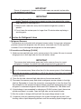
IMPORTANT
Only qualied service technicians should attempt to service or maintain this
unit. No such service or maintenance should be undertaken until the technician
has thoroughly read this Service Manual.
HOSHIZAKI provides this manual primarily to assist qualied service technicians in the
service and maintenance of the unit.
Should the reader have any questions or concerns which have not been satisfactorily
addressed, please call, write or send an e-mail message to the HOSHIZAKI Technical
Support Department for assistance.
HOSHIZAKI AMERICA, INC.
618 Highway 74 South
Peachtree City, GA 30269
Attn: HOSHIZAKI Technical Support Department
Phone: 1-800-233-1940 Technical Service
(770) 487-2331
Fax: 1-800-843-1056
(770) 487-3360
E-mail: techsuppor[email protected]
Web Site: www.hoshizaki.com
NOTE: To expedite assistance, all correspondence/communication MUST include the
following information:
• Model Number
• Serial Number
• Complete and detailed explanation of the problem

3
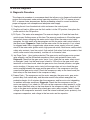
Please review this manual. It should be read carefully before the unit is serviced or
maintenance operations are performed. Only qualied service technicians should service
and maintain the unit. This manual should be made available to the technician prior to
service or maintenance.
CONTENTS
I. Specications ...................................................................................................................... 5
A. Icemaker ....................................................................................................................... 5
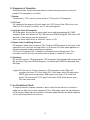
II. General Information ........................................................................................................... 6
A. Construction .................................................................................................................. 6
B. Ice Making Unit ............................................................................................................. 7
C. Control Box Layout ........................................................................................................ 8
a) Auxiliary Code K-1 and Earlier ............................................................................. 8
b) Auxiliary Code K-2 and L-0 ................................................................................... 8
c) Auxiliary Code L-1 and M-0 .................................................................................. 9
d) Auxiliary Code M-1 and Later ............................................................................... 9
D. Timer Board ................................................................................................................. 10
1. Solid-State Timer Board Control ............................................................................. 10
E. Sequence of Operation ................................................................................................11
1. Startup ....................................................................................................................11
2. Fill Cycle .................................................................................................................11
3. Ice Purge Cycle (60 seconds) ................................................................................. 11
4. Freeze Cycle (Ice Making Process) ........................................................................11
5. Shutdown: ..............................................................................................................11
F. Ice Production Check ....................................................................................................11
III. Technical Information ...................................................................................................... 13
A. Water Circuit and Refrigeration Circuit ........................................................................ 13
B. Wiring Diagram ............................................................................................................ 14
1. Auxiliary Code K-1 and Earlier ............................................................................... 14
2. Auxiliary Code K-2 and L-0 .................................................................................... 15
3. Auxiliary Code L-1 and M-0 ................................................................................... 16
4. Auxiliary Code M-1 and Later ................................................................................ 17
C. Sequence of Electrical Circuit ..................................................................................... 18
1. Fill Cycle ................................................................................................................ 18
2. Ice Purge Cycle ..................................................................................................... 19
3. Freeze Cycle ......................................................................................................... 20
4. Shutdown .............................................................................................................. 21
5. Cleaning - Flush Switch ........................................................................................ 22
6. Low Water Safety ................................................................................................... 23
7. Spout Safety Switch ............................................................................................... 24
8. High Pressure Switch ............................................................................................. 25
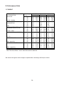
D. Performance Data ....................................................................................................... 26
IV. Service Diagnosis ........................................................................................................... 27
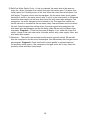
A. Diagnostic Procedure .................................................................................................. 27
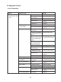
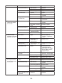
B. Diagnostic Charts ........................................................................................................ 29
1. No Ice Production ................................................................................................... 29
2. Low Ice Production ................................................................................................ 31
3. Other ...................................................................................................................... 32

4
V. Removal and Replacement of Components .................................................................... 33
A. Service for Refrigerant Lines ....................................................................................... 33
1. Refrigerant Recovery ............................................................................................ 33
2. Evacuation and Recharge [R-404A] ...................................................................... 33
B. Brazing ........................................................................................................................ 34
C. Removal and Replacement of Compressor ................................................................ 35
D. Removal and Replacement of Drier ............................................................................ 36
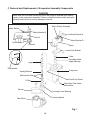
E. Removal and Replacement of Expansion Valve .......................................................... 36
F. Removal and Replacement of Evaporator Assembly Components .............................. 38
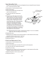
1. Upper Bearing Wear Check ...................................................................... 39
2. Removal and Replacement of Cutter ..................................................................... 39
3. Removal and Replacement of Extruding Head ...................................................... 40
4. Removal and Replacement of Auger ..................................................................... 40
5. Removal and Replacement of Evaporator ............................................................. 40
6. Removal and Replacement of Mechanical Seal and Lower Housing ................... 41
7. Removal and Replacement of Gear Motor ............................................................. 42
G. Removal and Replacement of Fan Motor ................................................................... 43
H. Removal and Replacement of Inlet Water Valve ......................................................... 43
I. Removal and Replacement of Flush Water Valve ......................................................... 43
VI. Cleaning and Maintenance ............................................................................................. 45
A. Cleaning and Sanitizing Instructions ........................................................................... 45
1. Cleaning Solution ................................................................................................... 45
2. Cleaning Procedure ............................................................................................... 45
3. Sanitizing Solution ................................................................................................. 46
4. Sanitizing Procedure - Initial .................................................................................. 47
5. Sanitizing Procedure - Final ................................................................................... 47
B. Maintenance ................................................................................................................ 49
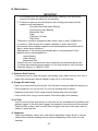
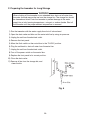
C. Preparing the Icemaker for Long Storage ................................................................... 50

5
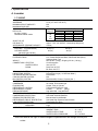
I. Specications
A. Icemaker
1. F-300BAF
Note: We reserve the right to make changes in specications and design without prior
notice.
AC SUPPLY VOLTAGE 115/60/1
AMPERAGE 9.0 A ( AT 104°F/ WT 80°F )
MINIMUM CIRCUIT AMPACITY N/A
MAXIMUM FUSE SIZE N/A
APPROXIMATE ICE PRODUCTION Ambient WATER TEMP. (°F)
PER 24 HR. Temp.(°F) 50 70 90
lbs./day ( kg/day ) 70 * 303 (137) 290 (131) 278 (126)
Reference without *marks 80 267 (121) 256 (116) 246 (112)
90 236 (107) * 232 (105) 218 (99)
100 209 (95) 201 (91) * 188 (85)
SHAPE OF ICE Flake
ICE QUALITY Approx. 70%, Ice (90/70°F, Conductivity 200 µs/cm)
APPROXIMATE STORAGE CAPACITY 110 lbs.
ELECTRIC & WATER CONSUMPTION 90/70°F 70/50°F
ELECTRIC W (kWH/100 lbs.) 674 (7.0) 667 (5.3)
POTABLE WATER 28 (12) 36 (12)
gal./24HR (gal./100 lbs.)
EXTERIOR DIMENSIONS (WxDxH) 36" x 24" x 33" (914 x 610 x 838 mm)
EXTERIOR FINISH PVC Coated Galvanized Steel; Galvanized Steel (Rear);
Stainless Steel (Top)
WEIGHT Net 182 lbs. ( 83 kg ), Shipping 221 lbs. ( 100 kg )
CONNECTIONS - ELECTRIC Cord Connection
- WATER SUPPLY Inlet 1/2" FPT
- DRAIN Drain Pan 3/4" FPT
Bin Drain 3/4" FPT
ICE MAKING SYSTEM Auger type
HARVESTING SYSTEM Direct Driven Auger ( 1/6 HP Gear Motor )
ICE MAKING WATER CONTROL Float Switch
COOLING WATER CONTROL N/A
BIN CONTROL SYSTEM Mechanical Bin Control ( Proximity Sw. )
COMPRESSOR Hermetic, Model JS25C1E-IAA-252
CONDENSER Air-cooled, Fin and tube type
EVAPORATOR Copper Tube on Cylinder
REFRIGERANT CONTROL Thermostatic Expansion Valve
REFRIGERANT CHARGE R-404A, 10.5 oz. (300 g)
DESIGN PRESSURE High 460 PSIG, Low 290 PSIG
P.C. BOARD CIRCUIT PROTECTION High Voltage Cut-off Relay
COMPRESSOR PROTECTION Auto-reset Overload Protector
GEAR MOTOR PROTECTION Manual reset Circuit Breaker
REFRIGERANT CIRCUIT PROTECTION Auto-reset High Pressure Control Switch
LOW WATER PROTECTION Float Switch and Timer
ACCESSORIES - SUPPLIED Ice Scoop, Spare Fuse
- REQUIRED Legs
OPERATING CONDITIONS VOLTAGE RANGE 104 - 127 V
AMBIENT TEMP. 45 - 100° F
WATER SUPPLY TEMP. 45 - 90° F
WATER SUPPLY PRESSURE 10 - 113 PSIG
ENG F-013.0.1196

6
II. General Information
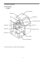
A. Construction
1. F-300BAF
*The switch actuator is located in the ice storage bin.
Ice Storage Bin
Sliding Door
Control Water Valve
Reservoir
Expansion Valve
Control Box
Air-cooled Condenser
Bin Control *
Spout
Evaporator
Gear Motor
Compressor

7
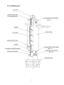
B. Ice Making Unit

8
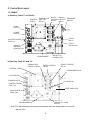
C. Control Box Layout
1. F-300BAF
a) Auxiliary Code K-1 and Earlier
Note: The above component names are identical with the wiring label, but not with
the parts list.
FLUSH SWITCH
POWER SWITCH
CONTROL BOARD
FUSE (1A)
GEAR MOTOR
FUSE (1.5A)
TRANSFORMER
CAPACITOR - GEAR
MOTOR
START CAPACITOR
FLUSH RELAY
PRESSURE SWITCH
WATER CONTROL
RELAY
GEAR MOTOR
PROTECT RELAY
CONTROL TIMER
CIRCUIT PROTECT
RELAY
TRANSFORMER
CAPACITOR
GEAR MOTOR
START
CAPACITOR
FLUSH
RELAY
PRESSURE
SWITCH
CIRCUIT
PROTECT
RELAY
WATER
CONTROL
RELAY
GEAR MOTOR
PROTECT
RELAY
CONTROL
TIMER
FLUSH
SWITCH
POWER
SWITCH
CONTROL BOARD
FUSE (1A)
CIRCUIT
BREAKER
GEAR MOTOR
b) Auxiliary Code K-2 and L-0

9
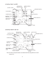
c) Auxiliary Code L-1 and M-0
FLUSH SWITCH
POWER SWITCH
CONTROL BOARD
FUSE (1A)
GEAR MOTOR
FUSE (1.5A)
TRANSFORMER
CAPACITOR - GEAR
MOTOR
START CAPACITOR
FLUSH RELAY
PRESSURE SWITCH
WATER CONTROL
RELAY
GEAR MOTOR
PROTECT RELAY
CONTROL TIMER
d) Auxiliary Code M-1 and Later
FLUSH SWITCH
POWER SWITCH
CONTROL BOARD
FUSE (1A)
GEAR MOTOR
FUSE (1.5A)
TRANSFORMER
CAPACITOR - GEAR
MOTOR
START CAPACITOR
FLUSH RELAY
PRESSURE SWITCH
WATER CONTROL
RELAY
GEAR MOTOR
PROTECT RELAY
CONTROL TIMER
Note: The above component names are identical with the wiring label, but not with
the parts list.
SAFETY RELAY
BIN CONTROL
SAFETY SWITCH
LAMP

10
D. Timer Board
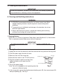
1. Solid-State Timer Board Control
• A HOSHIZAKI exclusive solid-state sequence timer board is employed in Hoshizaki self-
contained aker icemakers.
• All models are pre-tested and factory-adjusted.
CAUTION
1. Fragile, handle very carefully.
2. The timer board contains CMOS (Complementary Metal-Oxide
Semiconductor) integrated circuits, which are susceptible to failure due to
static discharge. It is especially important to use an anti-static wrist strap
when handling or replacing the board.
3. Do not touch the electronic devices on the board or the back of the board to
prevent damage to the board.
4. Do not change wiring and connections. Especially, never misconnect
terminals.
5. Do not x the electronic devices or parts on the board in the eld. Always
replace the whole board assembly if it goes bad.
The timer board provides the following safeguards:
• Provides component protection during low water supply.
• Purges remaining ice in the evaporator.
• Provides short cycle protection for the compressor.

11
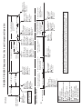
E. Sequence of Operation
Hoshizaki utilizes a solid state timer board to switch the components on and off as
needed. The sequence is as follows:
1. Startup
Flush switch in "ICE" position, power switch in "ON" position. FR energizes.
2. Fill Cycle
WV opens and the reservoir lls with water until UF/S closes. Note: GM will not start
unless UF/S is closed. For details, see "IV. Service Diagnosis".
3. Ice Purge Cycle (60 seconds)
WCR energizes, closing the low water safety circuit and de-energizing WV. GMR
energizes (clear relay located on TB). GM starts and GMPR energizes. GM runs for 60
seconds to clear any ice from the evaporator.
Note: Low water safety circuit is terminals 3 and 4 on TB.
4. Freeze Cycle (Ice Making Process)
CR energizes (black relay located on TB). Comp and FMS energize. As the water in the
evaporator cools, ice starts forming within 4 to 6 minutes. This time frame depends on
the inlet water and ambient temperature conditions.
UF/S and LF/S operate WV as needed to continue the ice making process. This
continues until BC shuts the ice maker down or power is turned off to the unit.
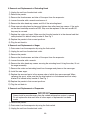
5. Shutdown:
BC activates (opens). FR de-energizes, FWV energizes. Approximately 90 seconds after
BC activates, Comp and FMS de-energize, one minute later GMPR de-energizes and
GM stops.
Legend: BC–bin control; Comp–compressor; CR–compressor relay; FMS–self-
contained fan motor; FR–ush relay; FWV–ush water valve; GM–gear motor;
GMPR–gear motor protect relay; GMR–gear motor relay; LF/S–lower oat
switch; TB–timer board; UF/S–upper oat switch; WCR–water control relay;
WV–inlet water valve.
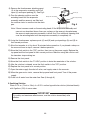
F. Ice Production Check
To check production, prepare a bucket or pan to catch the ice and a set of scales to
weigh the ice. After the unit has operated for 10 to 20 minutes, catch the ice production
for 10 minutes. Weigh the ice to establish the batch weight. Multiply the batch weight by
144 for the total production in 24 hours.

12
Legend:
BC - bin control
Comp - compressor
FMS - self-contained fan motor
FR - ush relay
FWV - ush water valve
GM - gear motor
GMPR - gear motor protect relay
LF/S - lower oat switch
TC - timer control
UF/S - upper oat switch
WCR - water control relay
WV - inlet water valve
UF/S open
LF/S open
90 sec. TC started
WCR de-energized
WV energized
Comp continues
GM continues
FMS continues
GMPR continues
FR continues
60 seconds
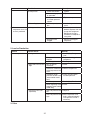
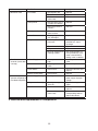
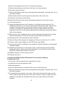
F-300BAF, F-500BAF Sequence Flow Chart and Component Operation
Bin control operation
1. Startup
2. Ice Purge Cycle
FR energized
WCR de-energized
WV energized
LF/S closed
UF/S closed
WCR energized
WV de-energized
GM energized
GMPR energized
FR continues
Comp energized
FMS energized
WCR continues
GM continues
GMPR continues
FR continues
Flush switch in "ICE"
Power switch "ON"
2. Shutdown & Restart
90 seconds
1. Bin control proximity switch
opens to stop ice production.
Comp de-energized
FMS de-energized
GM continues
GMPR continues
FWV continues
GM de-energized
GMPR de-energized
FWV continues
3. Gear motor de-energizes
and unit is "OFF"
6.7 sec.
60 seconds
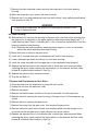
Components Energized when the Flush Switch is in the FLUSH Position
The FLUSH position is used when cleaning and sanitizing the machine. When in the FLUSH position, power is
supplied to the ush valve. This allows cleaner and sanitizer to drain from the evaporator assembly.
1. Fill Cycle
3. Icemaking Cycle
Rell Cycle
LF/S closed
UF/S closed
90 sec. TC ended
WCR energized
WV de-energized
Comp continues
GM continues
FMS continues
GMPR continues
FR continues
4. Low Water Safety
UF/S open
90 sec. TC exceeded
WCR de-energized
WV continues
Comp continues
GM continues
FMS continues
GMPR continues
FR continues
Comp de-energized
FMS de-energized
WV continues
GM continues
GMPR continues
FR continues
GM de-energized
GMPR de-energized
WV continues
FR continues
90 sec. timer
60 sec. timer
If rell > 90 sec. TC
60 sec. timer
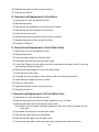
BC open
FR de-energized
WCR de-energized
FWV energized
Comp continues
FMS continues
GM continues
GMPR continues
2. Compressor and fan motor
de-energize, gear motor
continues running.
4. Bin control proximity switch
closes. Reservoir lls. LF/S
and UF/S close. Gear motor
starts 6.7 seconds later.
LF/S and UF/S close
WCR energized
WV de-energized
GM energized
GMPR energized
FR continues
BC closed
FR energized
WV energized
FWV de-energized
Comp energized
FMS energized
GM continues
GMPR continues
WCR continues
FR continues
5. Compressor and fan
motor energize. Ice
production begins in 4
to 6 minutes.
UF/S closes terminating
90 sec TC.
LF/S opens
initiating rell
and 90 sec. TC
Low water safety ciruit
closed. (Terminals 3
and 4 on timer board)
If rell achieved, icemaking
cycle starts and timers
are reset.

13
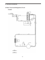
III. Technical Information
A. Water Circuit and Refrigeration Circuit
F-300BAF

14
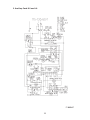
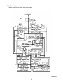
B. Wiring Diagram
1. Auxiliary Code K-1 and Earlier
F-300BAF

15
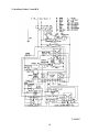
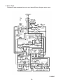
2. Auxiliary Code K-2 and L-0
F-300BAF

16
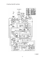
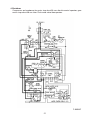
3. Auxiliary Code L-1 and M-0
F-300BAF

17
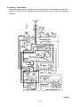
4. Auxiliary Code M-1 and Later
F-300BAF

18
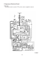
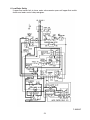
C. Sequence of Electrical Circuit
1. Fill Cycle
When power switch is moved to "ON" position, water is supplied to reservoir.
F-300BAF

19
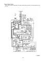
2. Ice Purge Cycle
When reservoir has lled, gear motor starts.
F-300BAF

20
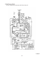
3. Freeze Cycle
Compressor and condenser fan motor start about 60 sec. after gear motor starts.
F-300BAF
Page is loading ...
Page is loading ...
Page is loading ...
Page is loading ...
Page is loading ...
Page is loading ...
Page is loading ...
Page is loading ...
Page is loading ...
Page is loading ...
Page is loading ...
Page is loading ...
Page is loading ...
Page is loading ...
Page is loading ...
Page is loading ...
Page is loading ...
Page is loading ...
Page is loading ...
Page is loading ...
Page is loading ...
Page is loading ...
Page is loading ...
Page is loading ...
Page is loading ...
Page is loading ...
Page is loading ...
Page is loading ...
Page is loading ...
Page is loading ...
-
 1
1
-
 2
2
-
 3
3
-
 4
4
-
 5
5
-
 6
6
-
 7
7
-
 8
8
-
 9
9
-
 10
10
-
 11
11
-
 12
12
-
 13
13
-
 14
14
-
 15
15
-
 16
16
-
 17
17
-
 18
18
-
 19
19
-
 20
20
-
 21
21
-
 22
22
-
 23
23
-
 24
24
-
 25
25
-
 26
26
-
 27
27
-
 28
28
-
 29
29
-
 30
30
-
 31
31
-
 32
32
-
 33
33
-
 34
34
-
 35
35
-
 36
36
-
 37
37
-
 38
38
-
 39
39
-
 40
40
-
 41
41
-
 42
42
-
 43
43
-
 44
44
-
 45
45
-
 46
46
-
 47
47
-
 48
48
-
 49
49
-
 50
50


Hoshizaki Inflatable Bouncy Toy F-300BAF User manual
- Category
- Ice cube makers
- Type
- User manual
- This manual is also suitable for
Ask a question and I''ll find the answer in the document
Finding information in a document is now easier with AI
Related papers
-
Hoshizaki F-300BAF User manual
-
 Hoshizaki American, Inc. F-300BAF User manual
-
Hoshizaki F-500BAF User manual
-
-
-
-
Hoshizaki American, Inc. F-330BAH-C User manual
-
-
 Hoshizaki American, Inc. F-450MAH User manual
-


Other documents
-
GE ZDIW50 User manual
-
 Hoshizaki American, Inc. DCM-270BAH User manual
-
GE ZDIW50YB Owner's manual
-
 Hoshizaki American, Inc. DB-130C User manual
-
Ice-O-Matic ICEF 155 User manual
-
 Hoshizaki American, Inc. C-100BAF-ADDS User manual
-
Diamond ICE115AS-R2 User manual
-
 SIMAG SMI80 Owner's manual
-
 Hoshizaki American, Inc. KMD-410MAH User manual
-
Hoshizaki American, Inc. KMD-901MRH User manual


