Hoshizaki F-500BAF is a self-contained flaker ice maker capable of producing up to 500 lbs of ice per day. It features a stainless steel exterior and interior, a built-in storage bin, and an air-cooled condenser. The F-500BAF is ideal for use in restaurants, bars, and other commercial applications where a steady supply of fresh ice is needed.
Hoshizaki F-500BAF is a self-contained flaker ice maker capable of producing up to 500 lbs of ice per day. It features a stainless steel exterior and interior, a built-in storage bin, and an air-cooled condenser. The F-500BAF is ideal for use in restaurants, bars, and other commercial applications where a steady supply of fresh ice is needed.


-
 1
1
-
 2
2
-
 3
3
-
 4
4
-
 5
5
-
 6
6
-
 7
7
-
 8
8
-
 9
9
-
 10
10
-
 11
11
-
 12
12
-
 13
13
-
 14
14
-
 15
15
-
 16
16
-
 17
17
-
 18
18
-
 19
19
-
 20
20
-
 21
21
-
 22
22


Hoshizaki F-500BAF is a self-contained flaker ice maker capable of producing up to 500 lbs of ice per day. It features a stainless steel exterior and interior, a built-in storage bin, and an air-cooled condenser. The F-500BAF is ideal for use in restaurants, bars, and other commercial applications where a steady supply of fresh ice is needed.
Ask a question and I''ll find the answer in the document
Finding information in a document is now easier with AI
Related papers
-
Hoshizaki American, Inc. F-500BAF(-C) User manual
-
-
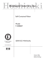 Hoshizaki American, Inc. F-300BAF User manual
-
 Hoshizaki American, Inc. F-300BAF User manual
-
 Hoshizaki American, Inc. F-450MAH User manual
-
Hoshizaki F-300BAF User manual
-
Hoshizaki American, Inc. F-330BAH-C User manual
-
Hoshizaki American, Inc. FS-1001MLH/-C User manual
-
Hoshizaki DCM-500BWH User manual
-
Hoshizaki American, Inc. CUBELET ICEMAKER/DISPENSER DCM-750BAH-OS User manual