Page is loading ...

Page 1
Page 1
SERVICE MANUAL
ICE UNDERCOUNTER SERIES CUBER
MODEL
ICEF 155
Rev. 07/2014

Page 2
Page 2
TABLE OF
CONTENTS
2
3
Table of contents page
Specifications
GENERAL INFORMATION AND INSTALLATION
Introduction
Unpacking and Inspection
Location and levelling
Electrical connections
Water supply and drain connections
Final check list
Installation practice
OPERATING INSTRUCTIONS
Start up
Operational checks
PRINCIPLE OF OPERATION (How it works)
Water circuit
Refrigerant circuit
Mechanical system
Operating pressures
Components description
Wiring diagram
Service diagnosis
MAINTENANCE AND CLEANING INSTRUCTIONS
General
Icemaker
Cleaning instructions of water system
13
13
15
16
17
5
5
5
5
6
6
7
8
10
25
27
29
29
29

Page 3
Page 3
SPECIFICATIONS
ice making capacity
ELECTRONIC FLAKER MODEL ICEF 155
NOTE. With the unit in “built-in” conditions, the ice production is gradually reduced in respect to the
levels shown in the graph, up to a maximum of 10% at room temperatures higher than 32
°
C.
The daily ice-making capacity is directly related to the condenser air inlet temperature, water
temperature and age of the machine.
To keep your FLAKER at peak performance levels, periodic maintenance checks must be carried
out as indicated on page 29 of this manual.
Important operating requirements:
MIN MAX
- Air temperature 10°C (50°F) 40°C (100°F)
- Water temperature 5°C (40°F) 40°C (100°F)
- Water pressure 1 bar (14 psi) 5 bars (70 psi)
- Electr. voltage
variations fromvoltage
rating specified
on nameplate -10% +10%
32
38
10
21
75
70
65
60
55
50
45
Kg.
32
°C21 15
°C
o
o
AIR COOLED MODELS
WATER TEMPERATURE
AMBIENT TEMPERATURE
ICE PRODUCED PER 24 HRS.
32
38
10
21
75
70
65
60
55
50
45
Kg.
32
°C21 15
°C
o
o
WATER COOLED MODELS
WATER TEMPERATURE
AMBIENT TEMPERATURE
ICE PRODUCED PER 24 HRS.

Page 4
Page 4
Start Electric power cons.
Amps Kwh per 24 HR
Basic electr. Amps Watts Nr. of wires Amps fuse
SPECIFICATIONS
Model Cond. unit Finish Comp. HP
Ice bin
cap
Water req.
lt/24 HR
ICEF 155 - MACHINE SPECIFICATIONS
Dimensions:
HEIGHT (less legs) 794 mm.
HEIGHT (with legs) 929 mm.
WIDTH 529 mm.
DEPTH 621 mm.
WEIGHT 51 Kg.
230/50/1 2.2 11 330 7.5 3 x 1.5 mm
2
10
S. Steel 1/4 25 Kg.
ICEF 155 AS Air 53**
ICEF 155 WS Water 300*
* A 15°C water temperature

Page 5
Page 5
GENERAL INFORMATION AND INSTALLATION
A. INTRODUCTION
This manual provides the specifications and the
step-by-step procedures for the installation, start-
up and operation, maintenance and cleaning for
the ICEF 155 icemakers.
This Electronic Flaker is quality designed,
engineered and manufactured.
Their ice making systems are thoroughly tested
providing the utmost in flexibility to fit the needs
of a particular user.
NOTE. To retain the safety and performance
built into this icemaker, it is important that
installation and maintenance be conducted
in the manner outlined in this manual.
B. UNPACKING AND INSPECTION
1. Call the authorized Distributor or Dealer for
proper installation.
2. Visually inspect the exterior of the packing
and skid. Any severe damage noted should be
reported to the delivering carrier and a concealed
damage claim form filled in subjet to inspection of
the contents with the carrier’s representative
present.
3. a) Cut and remove the plastic strip securing
the carton box to the skid.
b) Cut open the top of the carton and remove
the polystyre protection sheet.
c) Pull out the polystyre posts from the
corners and then remove the carton.
4. Remove the front and the rear panels of the
unit and inspect for any concealed damage.
Notify carrier of your claim for the concealed
damage as stated in step 2 above.
5. Remove all internal support packing and
masking tape. (Leg package and water inlet and
outlet hoses are located in the storage bin
compartment).
6. Check that refrigerant lines do not rub against
or touch other lines or surfaces, and that the fan
blades move freely.
7. Check that the compressor fits snugly onto
all its mounting pads.
8. Use clean damp cloth to wipe the surfaces
inside the storage bin and the outside of the
cabinet.
9. See data plate on the rear side of the unit
and check that local main voltage corresponds
with the voltage specified on it.
CAUTION. Incorrect voltage supplied to
the icemaker will void your parts
replacement program.
10. Remove the manufacturer’s registration card
from the inside of the User Manual and fill-in all
parts including: Model and Serial Number taken
from the data plate.
Forward the completed self-addressed
registration card to the manufacturer.
11. If necessary fit the four legs into their seats
on the machine base and adjust them to the
desired level.
C. LOCATION AND LEVELLING
WARNING. This Ice Flaker is designed for
indoor installation only. Extended periods
of operation at temperature exceeding
the following limitations will constitute
misuse under the terms of the
Manufacturer’s Limited Warranty
resulting in LOSS of warranty coverage.
1. Position the unit in the selected permanent
location.
Criteria for selection of location include:
a) Minimum room temperature 10°C (50°F)
and maximum room temperature 40°C (100°F).
b) Water inlet temperatures: minimum 5°C
(40°F) and maximum 35°C (90°F).
c) Well ventilated location for air cooled models
(Clean the air cooled condenser at frequent
intervals).
d) Service access: adequate space must be
left for all service connections through the rear of
the ice maker. A minimum clearance of 15 cm
(6") must be left at the sides of the unit for routing
cooling air drawn into and exhausted out of the
compartment to maintain proper condensing
operation of air cooled models.
2. Level the unit in both the left to right and front
to rear directions.
D. ELECTRICAL CONNECTIONS
See data plate for current requirements to
determine wire size to be used for electrical
connections. All icemakers require a solid earth
wire.

Page 6
Page 6
All ice machines are supplied from the factory
completely pre-wired and require only electrical
power connections to the wire cord provided at
the rear of the unit.
Make sure that the ice machine is connected to
its own circuit and individually fused (see data
plate for fuse size).
The maximum allowable voltage variation should
not exceed -10% and +10% of the data plate
rating. Low voltage can cause faulty functioning
and may be responsible for serious damage to
the overload switch and motor windings.
NOTE. All external wiring should conform to
national, state and local standards and
regulations.
Check voltage on the line and the ice maker’s
data plate before connecting the unit.
E. WATER SUPPLY AND DRAIN
CONNECTIONS
GENERAL
When choosing the water supply for the ice flaker
consideration should be given to:
a) Length of run
b) Water clarity and purity
c) Adequate water supply pressure
Since water is the most important single ingredient
in producting ice you cannot emphasize too
much the three items listed above.
Low water pressure, below 1 bar may cause
malfunction of the ice maker unit.
Water containing excessive minerals will tend to
produce scale build-up on the interior parts of the
water system while too soft water (with too lo
contents of mineral salts), will produce a very
hard flaker ice.
WATER SUPPLY
Connect the 3/4" GAS male of the water inlet
fitting, using the flexible hose supplied to the cold
water supply line with regular plumbing fitting
and a shut-off valve installed in an accessible
position between the water supply line and the
unit.
If water contains a high level of impurities, it is
advisable to consider the installation of an
appropriate water filter or conditioner.
WATER SUPPLY - WATER COOLED MODELS
The water cooled versions of Ice Makers require
two separate inlet water supplies, one for the
water making the flaker ice and the other for the
water cooled condenser.
Connect the 3/4" GAS male fitting of the water
inlet, using the flexible hose supplied to the cold
water supply line with regular plumbing fitting
and a shut-off valve installed in an accessible
position between the water supply line and the
unit.
WATER DRAIN
The recommended drain tube is a plastic or
flexible hose with 18 mm (3/4") I.D. which runs to
an open trapped and vented drain. When the
drain is a long run, allow 3 cm pitch per meter
(1/4" pitch per foot).
Install a vertical open vent on drain line high point
at the unit drain connection to ensure good
draining.
The ideal drain receptacle is a trapped and
vented floor drain.
WATER DRAIN - WATER COOLED MODELS
Connect the 3/4" GAS male fitting of the
condenser water drain, utilizing a second flexible
hose to the open trapped and vented drain.
This additional drain line must not interconnect to
any other of the units drains.
NOTE. The water supply and the water drain
must be installed to conform with the local
code. In some case a licensed plumber and/
or a plumbing permit is required.
F. FINAL CHECK LIST
1. Is the unit in a room where ambient
temperatures are within a minimum of 10°C
(50°F) even in winter months?
2. Is there at least a 15 cm (6") clearance
around the unit for proper air circulation?
3. Is the unit level? (IMPORTANT)
4. Have all the electrical and plumbing
connections been made, and is the water supply
shut-off valve open?
5. Has the voltage been tested and checked
against the data plate rating?
6. Has the water supply pressure been checked
to ensure a water pressure of at least 1 bar
(14 psi).
7. Have the bolts holding the compressor down
been checked to ensure that the compressor is
snugly fitted onto the mounting pads?

Page 7
Page 7
11. Has the Manufacturer’s registration card
been filled in properly? Check for correct model
and serial number against the serial plate and
mail the registration card to the factory.
12. Has the owner been given the name and the
phone number of the authorized Service Agency
serving him?
8. Check all refrigerant lines and conduit lines
to guard against vibrations and possible failure.
9. Have the bin liner and cabinet been wiped
clean?
10. Has the owner/user been given the User
Manual and been instructed on the importance of
periodic maintenance checks?
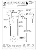
G. INSTALLATION PRACTICE
1. Hand shut-off valve
2. Water filter
3. Water supply line
(flexible hose)
4. 3/4" GAS male fitting
5. Power line
6. Main switch
7. Drain fitting
8. Vented drain
9. Open trapped vented
drain
WARNING. This icemaker is not designed for outdoor installation and will not function in
ambient temperatures below 10°C (50°F) or above 40°C (100°F).
This icemaker will malfunction with water temperatures below 5°C (40°F) or above 35°C
(90°F).

Page 8
Page 8
2
1
L
N
COMPRESSOR
9
10
11
12
13
3
4
5
6
7
8
CONTACTOR COIL
GEAR MOTOR
FAN MOTOR
ELECTRONIC
CARD
RELAYS
TRIAC
RESET
S E N S O R S
DATA PROCESSOR
WATER
LEVEL
GEAR MOTOR ROTATION
CONDENSER TEMP.
EVAPORATOR TEMP.
ICE LEVEL CONTROL
TRANSF.
T>1°C
OPERATING INSTRUCTIONS
B. Elapsed the 3 minutes - stand by period - the
unit starts operating with the activation in
sequence of the following assemblies:
GEAR MOTOR
COMPRESSOR
FAN MOTOR (if unit is an air cooled version)
kept under control by the condenser temperatu-
re sensor which has its probe within the condenser
fins (Fig.2).
C. After 2 or 3 minutes from the compressor
start up, observe that flaker ice begins dropping
off the ice spout to fall into the storage bin.
NOTE. The first ice bits that drop into the ice
storage bin are not so hard as the evaporating
temperature has not yet reached the correct
operating value. It is necessary to allow the
ice - just made - to cure itself and wait for
about ten minutes for the evaporating tem-
perature to reach the correct value so to
make more hard bits of ice.
L
N
11
10
9
1
2
7
8
6
5
4
3
13
12
FIG. 1
START UP
After having correctly installed the ice maker and
completed the plumbing and electrical
connections, perform the following “Start-up”
procedure.
A. Open the water supply line shutoff valve and
put the unit under electrical power by moving the
main switch, on the power supply line, to the ON
position.
The first LED - GREEN - will glow to signal that
unit is under power.
NOTE. Every time the unit is put under
power, after being kept for sometime in shut-
off conditions (electrically disconnected) the
RED LED will blink for 3 minutes after which
the unit will start up with the immediate
operation of the gear motor assembly and,
after few seconds, of the compressor assy
(Fig.1).

Page 9
Page 9
FIG. 2
2
1
L
N
COMPRESSOR
9
10
11
12
13
3
4
5
6
7
8
CONTACTOR COIL
GEAR MOTOR
FAN MOTOR
ELECTRONIC
CARD
RELAYS
TRIAC
RESET
S E N S O R S
WATER
LEVEL
GEAR MOTOR ROTATION
CONDENSER TEMP.
EVAPORATOR TEMP.
ICE LEVEL CONTROL
TRANSF.
T 40÷50°C
DATA PROCESSOR
L
N
11
10
9
1
2
7
8
6
5
4
3
13
12
FIG. 3
2
1
L
N
COMPRESSOR
9
10
11
12
13
3
4
5
6
7
8
CONTACTOR COIL
GEAR MOTOR
FAN MOTOR
ELECTRONIC
CARD
RELAYS
TRIAC
RESET
S E N S O R S
WATER
LEVEL
GEAR MOTOR ROTATION
CONDENSER TEMP.
EVAPORATOR TEMP.
ICE LEVEL CONTROL
TRANSF.
T>75°C
DATA PROCESSOR
L
N
11
10
9
1
2
7
8
6
5
4
3
13
12

Page 10
Page 10
FIG. 4
2
1
L
N
COMPRESSOR
9
10
11
12
13
3
4
5
6
7
8
CONTACTOR COIL
GEAR MOTOR
FAN MOTOR
ELECTRONIC
CARD
RELAYS
TRIAC
RESET
S E N S O R S
WATER
LEVEL
GEAR MOTOR ROTATION
CONDENSER TEMP.
EVAPORATOR TEMP.
ICE LEVEL CONTROL
TRANSF.
DATA PROCESSOR
L
N
11
10
9
1
2
7
8
6
5
4
3
12
13
NOTE. If, after ten minutes from the
compressor start-up, the evaporating tem-
perature has not dropped down to a value
lower than -1
°
C (30
°
F) due to an insufficient
quantity of refrigerant in the system, the
evaporating temperature sensor detects such
an abnormal situation and stops consequently
the unit operation.
In this circustance, the 5th warning YELLOW
LED will blink.
The machine will remain in OFF mode for
one hour then it will restart automatically.
In case the unit trips OFF again in alarm for
3 times in 3 hours, the machine SHUTS OFF
DEFINITIVELY.
After having diagnosed and eliminated the
cause of the poor evaporating temperature
(insufficient refrigerant in the system, etc.) it
is necessary to unplug and plug in again to
restart the machine.
The unit, before resuming the total operation,
will go through the usual 3 minutes STAND-
BY period.
OPERATION CHECKS UPON THE UNIT
START UP
D. Remove front service panel and if necessary
install the refrigerant service gauges on the
corresponding Service valves to check both the
HI and LO refrigerant pressures.
NOTE. On air cooled models, the condenser
temperature sensor, which is located within
the condenser fins, keep the head
(condensing) pressure between 8.5 and 9.5
bar (120
÷
135 psig).
In case of condenser clogging such to prevent
the proper flow of the cooling air or, in case
the fan motor is out of operation or shortage
of water in the water cooled condenser, the
condenser temperature rises and when it
reaches 70
°
C (160
°
F) - for air cooled version
- and 60
°
C (140
°
F) - for water cooled version
- the condenser temperature sensor shuts-
off the ice maker with the consequent light-up
of the RED WARNING LIGHT (Fig.3).
The machine will remain in OFF mode for
one hour then it will restart automatically.
In case the unit trips OFF again in alarm for
3 times in 3 hours, the machine SHUTS OFF
DEFINITIVELY.
After having diagnosed the reason of the
temperature rise and removed its cause, it is
necessary to proceed as per the previous
“NOTE” to start up again the operation of the
ice maker.
E. Check for the correct CUT-OUT and
CUT-IN of the float reservoir water level
sensors by first shutting closed the water shutoff
valve on the water supply line.

Page 11
Page 11
FIG. 5
2
1
L
N
COMPRESSOR
9
10
11
12
13
3
4
5
6
7
8
CONTACTOR COIL
GEAR MOTOR
FAN MOTOR
ELECTRONIC
CARD
RELAYS
TRIAC
RESET
S E N S O R S
WATER
LEVEL
GEAR MOTOR ROTATION
CONDENSER TEMP.
EVAPORATOR TEMP.
ICE LEVEL CONTROL
TRANSF.
DATA PROCESSOR
L
N
11
10
9
1
2
7
8
6
5
4
3
12
13
This will cause a gradual decrease of the water
level in the float reservoir and as soon as the level
gets below the sensors, the flaker stops to ope-
rate and the YELLOW warning LED will glow to
signal the shortage of water (Fig. 4).
NOTE. The water level sensor detects the
presence of sufficient water in the float
reservoir and confirms it to the micro
processor by maintaining a low voltage
current flow between the two sensors using
the water as conductor.
WARNING. The use of de-mineralized
water (water with no salt content) having
an electrical conductivity lower than 30
µS, will cause the ability of the water
sensors to vanish with the consequent
CUT-OUT of the flaker operations and the
glowing of the YELLOW LED of shortage
of water, even though that water is indeed
in the reservoir.
After this, open the water supply line shutoff
valve to fill up again the float reservoir, the
YELLOW LED goes off while the RED LED
starts blinking.
After 3 minutes the unit resumes its total operation
with the immediate start-up of the gear motor
and, 2 seconds later, of the compressor.
F. Check for the correct operation of the
electronic eye of the ice bin level control, by
placing a hand in front of the ice spout and wait
till the ice cuts the light beam of the sensing
"eyes".
This interruption will cause an immediate blinking
of the Bin Full YELLOW LED located on the front
of the P.C. Board and after about 6 seconds
causes the shutoff of the unit with the
simultaneous lighting of the YELLOW LED
(steady) signalling the full bin situation (Fig. 5).
Remove the hand to discharge the ice into the
storage bin so to allow the resumption of the light
beam previously interrupted. After about 6
seconds the flaker will resume - through the 3
minutes STAND-BY period - the ice making
process with the extinguishing of the YELLOW
LED.

Page 12
Page 12
NOTE. The ICE LEVEL CONTROL
(INFRA-RED SYSTEM) is independent of
the temperature however, the reliability of
its detection can be affected by external
light radiations or by any sort of dirt and
scale sediment which may deposit
directly on the light source and on the
receiver.
To prevent any possible ice maker
malfunction, due to negative affection of
the light detector, it is advisable to locate
the unit where it is not reached by any
direct light beam or light radiation, also
it is recommended to keep the bin door
constantly closed.
NOTE. During the life of the machine the Ice
Level Control may require a recalibration
mainly when the glass of the two optical eyes
are covered by a thin lay of scale.
To do it just follow the following procedure:
• With unit OFF push and old the Reset
Button of the PC Board
• Give power to the machine through the
Green Master Switch
• Hold the PC Board Reset Button till the
leds start to blink/flash (more or less 10
seconds)
• Release the PC Board Reset Button
The Optical Ice Level Control is now
recalibrated.
Check for the correct operation of the Optical
Ice Level Control by plasing a handfull of ice
in between the two eyes.
The Bin Full yellow led must start to blink/
flash immediately and, 10 seconds later, the
machine must trip OFF.
M. If previously installed, remove the refrigerant
service gauges and re-fit the unit service panels
previously removed.
N. Instruct the owner/user on the general
operation of the ice machine and about the
cleaning and care it requires.

Page 13
Page 13
WATER CIRCUIT
The water enter in the machine through the water
inlet fitting which incorporates a strainer and it is
located at the rear side of the cabinet and then it
goes to the water reservoir flowing through a float
valve.
NOTE. The presence of the water in the float
reservoir is detected by a system of two
sensors which operates in conjunction with
the P.C. Board. The two sensors use the
water as a conductor to maintain a low voltage
current flow between them signalling in this
way to the P.C. Board the presence of the
water in the reservoir. In case the water used
is very soft (de-mineralized) or the float
reservoir gets empty the current flow between
the sensors become so weak or is no longer
maintained that, as consequence, the P.C.
Board shutoff the flaker operation with the
simultaneous glowing of the YELLOW LED
signalling “Shortage of water”.
The float reservoir is positioned at the side of the
freezing cylinder at such an height to be able to
maintain a constant water level around the freezer
auger.
In fact, the water flows from the reservoir into the
bottom inlet of the freezing cylinder to sorround
the stainless steel auger which is vertically fitted
in the center of the freezer.
In the freezer the incoming water gets chilled into
soft (slush) ice which is moved upward by the
rotating action of the auger. The stainless steel
auger that rotates counter-clockwise within the
freezer, is powered by a direct drive gear motor
and carries the ice upward along the refrigerated
freezer inner walls and by doing so the ice gets
progressively thicker and harder.
The ice, being costantly lifted up, meet the toothed
point of the ice breaker which is fitted on the top
end of the auger, where it gets compacted,
cracked and forced to change from vertical into
PRINCIPLE OF OPERATION
horizontal motion to be discharged out, through
the ice spout, into the storage bin.
By running the ice maker, i.e. by putting the unit
under power, starts the automatic and continuous
icemaking process which would not stop until the
ice storage bin gets filled-up to the level of the
control “eyes” located on the sides of the ice
spout.
As the ice level raises to interrupt the light beam
running between the two infrared Leds, the unit
stops after six seconds, with the simulteneous
glowing of the YELLOW LED signalling the “Full
Bin” situation.
NOTE. The interruption of the light beam
between the two light sensors is immediately
signalled by the blinking of the BIN FULL
YELLOW LED located on the front of the
P.C. Board.
After about 6" of steady interruption of the
light beam the unit stops and the “Full Bin”
YELLOW LED glows steady.
The six seconds of delay prevent the unit
from stopping for any undue reason like the
momentarily interruption of the light beam
caused by the flakes that slides along the ice
spout before dropping into the bin.
As some ice gets scooped out from the storage
bin, the light beam between the two sensors
resumes and six seconds later the ice machine
restarts the ice making process - going always
through the 3' stand by - and the YELLOW LED
goes off.
REFRIGERANT CIRCUIT
The hot gas refrigerant discharged out from the
compressor reaches the condenser where, being
cooled down, condenses into liquid.
Flowing into the liquid line it passes through the
drier filter, then it goes all the way through the
capillary tube where it looses some of its pressure
so that its pressure and temperature are lowered.
Next, the refrigerant enters into the evaporator
coil wrapped around the freezer inner tube.
The water being constantly fed at the interior of
the freezer inner tube, exchange heat with the
refrigerant circulating into the evaporator coil,
this cause the refrigerant to boil-off and evapora-
te, thereby it changes from liquid into vapor.
The vapor refrigerant then passes through the
suction accumulator and through the suction line
where the refrigerant exchanges heat with the
one flowing into the capillary tube (warmer) before
being sucked into the compressor to be
recirculated.
The refrigerant heat pressure is kept between
two pre-set values (8.5÷10 bar - 120÷140 psig)
by the condenser temperature sensor which has
its probe located within the condenser fins - in air
cooled versions.
This condenser temperature sensor, when
senses a rising of the condenser temperature
beyond the pre-fixed limit, changes its electrical
resistance and send a low voltage power flow to
ICE SPOUT
FLOAT TANK
FLOAT VALVE
FREEZER
FREEZER WATER
FEED LINE
WATER INLET LINE

Page 14
Page 14
FIG. 6
2
1
L
N
COMPRESSOR
9
10
11
12
13
3
4
5
6
7
8
CONTACTOR COIL
GEAR MOTOR
FAN MOTOR
ELECTRONIC
CARD
RELAYS
TRIAC
RESET
S E N S O R S
WATER
LEVEL
GEAR MOTOR ROTATION
CONDENSER TEMP.
EVAPORATOR TEMP.
ICE LEVEL CONTROL
TRANSF.
T<1°C
DATA PROCESSOR
the MICRO-PROCESSOR of the P.C. Board
which energizes, through a TRIAC, the Fan
Motor in ON-OFF mode.
When the opposite situation occures, i.e. the
condenser temperature gets below the pre-fixed
NOTE. In case the condenser temperature probe
s
enses that the condenser temperature has
rised to 70
°
C (160
°
F) - on air cooled versions
- or 60
°
C (140
°
F) - on water cooled versions -
for one of the following abnormal reasons:
CLOGGED CONDENSER (Air cooled version)
INSUFFICIENT FLOW OF COOLING
WATER (Water cooled version)
FAN MOTOR OUT OF OPERATION (Air
cooled version)
AMBIENT TEMPERATURE HIGHER THEN
43
°
C (110
°
F)
it causes the total and immediate SHUT-OFF
of the machine in order to prevent the unit
from operating in abnormal and dangerous
conditions. When the ice maker stops on
account of this protective device, there is a
simultaneous glowing of the RED LED,
warning the user of the Hi Temperature
situation. The machine will remain in OFF
mode for one hour then it will restart
automatically. In case the unit trips OFF again
in alarm for 3 times in 3 hours, the machine
SHUTS OFF DEFINITIVELY. After having
eliminated the source of the excessive con-
denser temperature, to restart the ice machine
it is necessary to unplug and plug in again.
The RED LED starts blinking and three
minutes later the flaker unit resume its normal
operating mode. The condenser temperatu-
re sensor has a further safety function which
consist in preventing the unit from operating
in Lo-ambient conditions i.e. when the
condenser body temperature - equivalent to
the ambient temperature - is lower then 1
°
C
34
°
F (Fig.6). As soon as the ambient tempe-
rature rises up to 5
°
C (40
°
F) the PC Board
will automatically restarts the machine
through the three minutes delay time.
L
N
11
10
9
1
2
7
8
6
5
4
3
12
13
limit, the temperature sensor changes again its
electrical resistance reducing therefore the
current flow to the P.C. Board to cause a
temporary stop of the Fan Motor.
On the water cooled versions, the refrigerant
head pressure is kept at the constant value of
9.5 bars (138 psig) by the metered amount of
water passing through the condenser which is
regulated by the action of the Water Regulating
Valve that has its capillary tube connected to the
liquid refrigerant line. As pressure increases, the
water regulating valve opens to increase the flow
of cooling water to the condenser.
ACCUMULATOR
CAPILLARY TUBE
COMPRESSOR
DISCHARGE LINE
CONDENSER
SUCTION LINE
FAN MOTOR
EVAPORATOR

Page 15
Page 15
directly fitted in the gear case through which it
drives - in counter clockwise rotation at a speed
of 9.5 r.p.m. - the freezer auger being linked to it
by the ratched coupling.
NOTE. In the event the gear motor will tend
to rotate in the wrong direction (counter-
clockwise) or not rotating at all or rotating at
lower speed the unit will stop immediately
with the glowing of the WARNING YELLOW
LED on account of the intervention of the
Electromagnetic Safety Device - based on
Hall Effect principle.
The machine will remain in OFF mode for
one hour then it will restart automatically.
In case the unit trips OFF again in alarm for
3 times in 3 hours, the machine SHUTS OFF
DEFINITIVELY.
After having diagnosed and eliminated the
source of the failure, to restart the unit it is
necessary to switch OFF and ON the power
line main disconnnect switch (Fig. 7).
The RED LED will start blinking and after
3 minutes the ice maker will resume its total
operations by running first the gear motor
and then the compressor.
FIG. 7
2
1
L
N
COMPRESSOR
9
10
11
12
13
3
4
5
6
7
8
CONTACTOR COIL
GEAR MOTOR
FAN MOTOR
ELECTRONIC
CARD
RELAYS
TRIAC
RESET
S E N S O R S
WATER
LEVEL
GEAR MOTOR ROTATION
CONDENSER TEMP.
EVAPORATOR TEMP.
ICE LEVEL CONTROL
TRANSF.
DATA PROCESSOR
L
N
11
10
9
1
2
7
8
6
5
4
3
12
13
The refrigerant suction or Lo-pressure sets - in
normal ambient conditions (21 °C) - on the value
of 0.4÷0.5 bar (6÷7 psig) after few minutes from
the unit start-up.
This value can vary of 0.1 or 0.2 bar (1.5
÷
3 psig)
in relation to the water temperture variations
influencing the freezer cylinder.
NOTE. If, after ten minutes from the unit start
up, no ice is made and the evaporating
temperature detected by the evaporator
sensor results to be higher than -1
°
C (30
°
F)
the ice maker stops and the 5TH WARNING
YELLOW LED blinks.
The machine will remain in OFF mode for
one hour then it will restart automatically.
In case the unit trips OFF again in alarm for
3 times in 3 hours, the machine SHUTS OFF
DEFINITIVELY.
MECHANICAL SYSTEM
The mechanical system of the SCOTSMAN Flaker
machines consists basically of a gear motor
assembly which drives, through a ratched
coupling, a worn shaft or auger placed on its
vertical axis within the freezing cylinder.
The gear motor is made of a single phase electric
motor with a permanent capacitor. This motor is

Page 16
Page 16
REFRIGERANT METERING DEVICE:
capillary tube
REFRIGERANT CHARGE (R 134 A)
air cooled water cooled
ICEF 155 340 gr 310 gr
NOTE. Before charging the refrigerant system
always check the type of refrigerant and
quantity as specified on the individual ice
machine dataplate.
The refrigerant charges indicated are relatives
to averages operating conditions.
OPERATING PRESSURES
(With 21°C ambient temperature)
Discharge pressure:
Air cooled version 8.5 ÷ 10 bar
123 ÷ 145 psig
Water cooled version 9.5 bar
140 psig
Suction pressure: 0.4 ÷ 0.8 bar
6 ÷ 12 psig

Page 17
Page 17
COMPONENTS DESCRIPTION
A. EVAPORATOR TEMPERATURE SENSOR
The evaporator sensor probe is inserted into its
tube well, which is welded on the evaporator
outlet line, it detects the temperature of the
refrigerant on the way out from the evaporator
and signals it by suppying a low voltage current
flow to the P.C. Board Micro-Processor.
According to the current received, the micro-
processor let the ice maker to continue its
operations. In case the evaporating temperatu-
re, after 10 minutes from the unit start-up, does
not go below -1°C (30°F) due to shortage of
refrigerant in the system the evaporator sensor
signal reaching the microprocessor is such to
stop immediately the unit operation, with the 5th
Warning YELLOW LED that blinks.
NOTE. The machine will remain in OFF mode
for one hour then it will restart automatically.
In case the unit trips OFF again in alarm for
3 times in 3 hours, the machine SHUTS OFF
DEFINITIVELY.
To restart the unit after the shutoff caused by
the hi evaporating temperature, it is neces-
sary to switch OFF and ON the power line
main disconnect Switch.
B. WATER LEVEL SENSOR
This sensor system consist of two small stainless
steel rods vertically fitted on the inner face of the
reservoir cover and electrically connected to the
low voltage circuit of the P.C. Board. When the
cover of the reservoir is positioned in its place the
tips of both the rods dip into the reservoir water
and detects and signals its presence by making
use of its electrical resistance.
NOTE. In the event of shortage of water in
the reservoir or, in case the water used is too
soft (de-mineralized) to cause greater
resistence to the current flow (conductivity
lower than 30
µ
S) this sensor system causes
the shutoff of the machine, to protect it from
running with an interrupted or inadequate
water supply. In this situation the YELLOW
LED will glow to warn of the machine shutoff
and the reason why.
C. CONDENSER TEMPERATURE SENSOR
The condenser temperature sensor probe,
located within the condenser fins (air cooled
version) or in contact with the tube coil (water
cooled version) detects the condenser tempera-
ture variations and signals them by supplying
current, at low voltage, to the P.C. BOARD.
In case the condenser temperature sensor
detects a temperature at the condenser lower
than +1°C (33°F) that signify that the ambient
temperature is at the same value, therefore it is
too low for the correct unit operation, the sensor
signals to the microprocessor to stop immediately
or to do not start the unit operations up to the
moment that the ambient temperature will rise to
more acceptables conditions (5°C).
In the air cooled versions, in relation to the
different current received, the micro processor of
the P.C. BOARD supplies, through a TRIAC, the
power at high voltage to the fan motor so that it
can cool the condenser and reduce its tempera-
ture.
In the event the condenser temperature rises
and reaches 70°C or 60°C the current arriving to
the micro processor is such to cause an imme-
diate and total stop of the machine operation.
NOTE. The machine will remain in OFF
mode for one hour then it will restart automa-
tically. In case the unit trips OFF again in
alarm for 3 times in 3 hours, the machine
SHUTS OFF DEFINITIVELY.
To restart the unit after the shutoff caused by
the hi condenser temperature, it is necessary
to switch OFF and ON the power line main
disconnect Switch.
D. GEAR MOTOR ROTATION AND SPEED
SENSOR
This safety device is housed on top of the Drive
Motor and detects - based on Hall Effect principle
- the rotating speed and rotating direction of the
drive Motor.
Should the rotating speed drop below
1300 r.p.m. the magnitude measured by this
device is such to signal to the microprocessor to
stop the unit and light-up the YELLOW LED.
About the same reaction occures when the drive
motor will tend to rotate in the wrong direction
(counterclockwise) situation that, if it occures,
will greatly affect all the freezer and gear reducer
components.
NOTE. The machine will remain in OFF
mode for one hour then it will restart automa-
tically. In case the unit trips OFF again in
alarm for 3 times in 3 hours, the machine
SHUTS OFF DEFINITIVELY. To restart the
unit after the shutoff caused by this safety
device, it is necessary first to eliminate the
cause that has generated the intervention of
the device and then switch OFF and ON the
power line main disconnect switch.
E. ICE BIN LEVEL LIGHT CONTROL
The electronic ice bin level control, located into
the ice spout, has the function to stop the operation
of the ice machine when the light beam between

Page 18
Page 18
the light source and the sensor gets interrupted
by the flake ice which accumulates in the spout.
When the light beam is interrupted the Bin Full
YELLOW LED located in the front of the P.C.
BOARD blinks; in case the light beam gets
interrupted for as long as 6 seconds, the ice
machine stops with the glowing-up of the 2nd
YELLOW LED to monitor the full ice bin situation.
The 6 seconds of delay prevents that any
minimum interruption of the light beam due to the
regular ice chuting through the ice spout may
stop the operation of the unit.
NOTE. During the life of the machine the Ice
Level Control may require a recalibration
mainly when the glass of the two optical eyes
are covered by a thin lay of scale.
To do it just follow the following procedure:
• With unit OFF push and old the Reset
Button of the PC Board
• Give power to the machine through the
Green Master Switch
• Hold the PC Board Reset Button till the
leds start to blink/flash (more or less 10
seconds)
• Release the PC Board Reset Button
The Optical Ice Level Control is now
recalibrated.
Check for the correct operation of the Optical
Ice Level Control by plasing a handfull of ice
in between the two eyes.
The Bin Full yellow led must start to blink/
flash immediately and, 10 seconds later, the
machine must trip OFF.
As soon as the ice is scooped out (with the
resumption of the light beam between the two
infrared sensor of ice level control) 10 seconds
later the ice machine resumes its operation with
the simul-taneous extinguishing the 2nd YELLOW
LED.
F. P.C. BOARD (Data processor)
The P.C. BOARD, fitted in its plastic box located
in the front of the unit, consists of two separated
printed circuits one at high and the other at low
voltage and protected by fuses. Also it consists of
five aligned LEDS monitoring the operation of the
machine of three jumpers (TEST used only in the
factory, 60/70°C used to set up the PC Board at
proper safety cut out condensing temperature
and 3' to by pass the 3 minutes Stand By) and of
input terminals for the leads of the sensor probes
as well as input and output terminals for the leads
of the ice maker electrical wires.
The P.C. BOARD is the brain of the system and
it elaborates, through its micro processor, the
signals received from the sensors in order to
control the operation of the different electrical
components of the ice maker (compressor, gear
motor, etc.).
The five LEDS, placed in a row in the front of the
P.C. BOARD, monitor the following situations:
GREEN LED
Unit under electrical
power
YELLOW LED
- Blinking: I/R beam cut
out
- Steady: unit shut-off at
storage bin full
- Blinking fast: I/R beam resumed
YELLOW LED
Unit shut-off due to a
too lo-water level into
float tank
RED LED
ON all the time
- Unit shut-off due to a too
hi-condensing temperature
- Unit shut-off due to a
too lo-ambient temperature
<+1°C
Blinking
3 minutes start up delay time
YELLOW LED
ON all the time
- Unit shut-off due to the wrong
rotation direction of gear motor
- Unit shut-off due to the
too lo speed of gear motor
Blinking
- Unit shut-off due to a
too hi-evaporating temp.
>-1°C after 10 min of operation
YELLOW AND
RED LED
- Blinking: Evaporator sensor
out of order
- Steady: Condenser sensor
out of order
- Blinking alternatively: Ice level
control out of order

Page 19
Page 19
H. EXTERNAL SWITCHES SOCKET
Connected to the external Green Master and
Red Alarm Reset Switches, it receives power
from the Master Switch as well as it provides
power to the Red Alarm switch in order to signal
any possible uncorrect operation condition of the
machine as clogged air filter (air cooled version
only) or short/missing of condensing water (water
cooled version) as detailed at item B.
It signal also the time for the cleaning of the water
system of the machine, cleaning that can be
change, according to the local water conditions,
from six month (standard - Jump In) to twelve
months (Jump Out).
Once cleaned the water system, it’s necessary to
cancel the time stored into the PC Board by
pushing and hold for more then 5" the Red Alarm
Re-Set Button till it stops to blink.
I. FLOAT RESERVOIR
The float reservoir consists of a plastic water pan
on which is fitted a float valve with its setting
screw. The float valve modulate the incoming
water flow to maintain a constant water level in
the reservoir, level that corresponds to the one in
the freezing cylinder to ensure proper ice formation
and fluidity.
On the inner side of the reservoir cover are fitted
the two water level sensors which detects the
presence or the shortage of water in the reservoir.
G. JUMPERS
The Flaker PC Board is equipped by three jumpers:
J1
PURGE Used on machine equipped with Water
Purge Valve to purge out the water
from the water system every 12 hours
and when the machine restart from the
Bin Full
JUMP IN - Purge activated
JUMP OUT - Purge disactivated
PWD Used to Pump Out the water by means
of the Progressive Water Pump
supplied as a kit
JUMP IN - No Progressive Water Pump
installed/in operation
JUMP OUT - Progressive Water Pump
installed/in operation
3’/60’ Delay time at start up
JUMP IN - 3 minutes delay
JUMP OUT - 60 minutes delay
J2
TEST Factory use ONLY
6/12 M
Cleaning remind for the water system -
Red Light blinks/flashes with machine
ON
JUMP IN - 12 months set up
JUMP OUT - 6 months set up
60/70°C Set up of the Safety Condensing
Temperature Sensor
JUMP IN - 70°C
JUMP OUT - 60°C
TO BY-PASS THE 3'/60' STAND BY TIME, SYMPLY JUMP "TEST" CONTACTS WITH PCB ENERGIZED

Page 20
Page 20
The drive motor rotor is kept aligned on its vertical
axis by two ball bearings permanently lubricated.
The gear case contains a train of three spur
gears the first one of which is in fiber to limit the
noise level. All the three gears are encased in
case bearings and are covered by lubricant grease
(MOBILPLEX IP 44).
Two seal rings, one fitted on the rotor shaft and
the other on the output shaft keep the gear case
sealed.
Hovewer, the interior can be inspected and
serviced by unbolting the two halves of the
aluminium gear case housing.
The gear reducer output shaft is connected to the
freezer auger by a ratched coupling which is
made of two toothed halves that engages
themselves only if turned in the correct direction
namely, conterclockwise.
M. FAN MOTOR (Air cooled version)
The fan motor is controlled through the P.C.
BOARD and the TRIAC by the condenser tempe-
rature sensor. Normally it operates to draw cooling
air through the condenser fins.
In cold ambient situation, the fan motor can run at
intermittance as the condenser pressure must be
kept between two corresponding head pressure
values 8.5÷9.5 bar - 120÷135 psig.
N. WATER REGULATING VALVE
(Water cooled version)
This valve controls the head pressure in the
refrigerant system by regulating the flow of water
going to the condenser.
As pressure increases, the water regulating val-
ve opens to increase the flow of cooling water.
O. COMPRESSOR
The hermetic compressor is the heart of the
refrigerant system and it is used to circulate and
retrieve the refrigerant throughout the entire
system. It compresses the low pressure refrigerant
vapor causing its temperature to rise and become
high pressure hot vapor which is then released
through the discharge valve.
NOTE. It is very important to make sure of the
correct fitting of the cover on the reservoir in
order to enable the sensor to efficiently control
the water situation avoiding undue shutoff
interventions.
J. FREEZING CYLINDER (EVAPORATOR)
The freezing cylinder is made of a stainless steel
vertical tube on which exterior is wrapped around
the cooling coil with the evaporating chamber
and in its interior is located the auger which
rotates on its vertical axis and it is maintained
aligned by the top and bottom bearings. A water
seal system is located in the bottom part of the
freezer while at the top end is fitted the ice
breaker.
The water constantly flowing into the cylinder
bottom part, freezes into ice when in contact with
the cylinder inner walls. The ice is then lifted up
by the rotating auger and compacted and forced
out by the ice breaker.
K. ICE BREAKER
The ice breaker is fitted in the freezer upper part
it has two breaker teeth to break the ice and with
its slanted shape from the rear tooth to the front
one it compacts and forces the ice out in an
horizontal way. By undergoing this, the ice looses
its excess of water content so it drops into the bin
in hard dry bits of ice.
In the ice breaker it is housed the top bearing
which is made of two rolls bearings positioned to
withstand the auger axial and radial loads. This
bearing is lubricated with a food grade - water
resistant grease.
NOTE. It is advisable to check the conditions
of both the lubricant grease and the top
bearing every six months.
L. DRIVE GEAR MOTOR
This motoreducer is made of a single phase
electric motor with permanent capacitor directly
fitted on a gear box.
/