


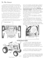
INTRODUCTION
Illust. 1
Internatianal Cub Cadet 122 Tractor.
Illust. 1A
International Cub Cadet 102 Tractor.
1

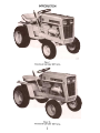
INTRODUCTION
Illust.2
International Cub Cadet 71 Tractor.
Page No.
De scription
Inside cover, I, 2
2
3, 4
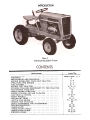
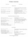
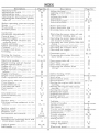
INTRODUCTION. CONTENTS. INSTRUMENTS AND CONTROLS. BEFORE OPERATING YOUR NEW TRACTOR .
OPERATING THE ENGINE FUEL SYSTEM. DRIVINGTHETRACTOR HITCHING TRAILING EQUIPMENT TO THE TRAC TOR
REARPQWERTAKE-OFF FRONT POWER TAKE-OFF ENGINE COOLING AND AIR CLEANER. ELECTRICALSYSTEM FRONT WHEELS. PNEUMATIC TIRES. CLUTCH AND BRAKE. STORING THE TRACTOR EXTRA EQUIPMENT AND ACCESSORIES TROUBLESHOOTING LUBRICATION. LUBRICATION TABLE. LUBRICATION GUIDE. SPECIFICATIONS. INDEX.
5. 6
6. 7
8. 9. 10
10. 11
12
13
14
14 to 19
20
20. 21
21. 22. 23
24
24
25. 26
26. 27
27
28 to 32
32 to 34
35

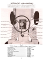
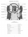
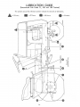
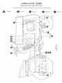
Illust. 3
Instruments and contrals on the International Cub Cadet 71, 102, and 122 Tractors.
Brakepedallock See pages 8 and 9.
Choke control button .See page 6.
Clutch and broke pedal See pages 21 and 22.
Creeper shift lever. See page 9.
Front power toke-off clutch lever.. See page 13.
Gearshift lever See page 9.
Ignition switch Seepage 14.
lift handle Seepage 11.
Lifthandlestop Seepage 11.
Lighting switch button. See pages 14 and 17.
Throttle lever. See page 5.
3


BEFORE OPERATING YOUR NEW TRACTOR
Lubrication. Lubricate the entire tractor. See pages 26 ta 32.
Check the air pressure. See pages 20 and 21.
Tires.
Fuel system.
Fill the fuel tank with gasoline. See page 6.
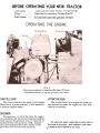
Illust.5
Fuel system and contrals on International Cub Cadet 123 Tractor.
(International Cub Cadet 71, 102 and 122 Tractars are similar.)
THROTTLE LEVER
LIFTING THE HOOD
The tractor hood is arranged to swing up
and forward to make the engine and fuel tank
readily accessible.
This lever controls the speed of the engine.
When set in a given position, it will maintaina
uniform engine speed.
GOVERNOR
The governor is set at the time the engine
is assembled and should not require readjust-
ment unless the governor arm is removed or
loosened from the governor shaft. Consult
your International Harvester dealer if the
gove rnor does not function properly.
To raise the hood, take hold of each side of
the hood at the rear, pull outward, and raise
it upward and forward to its stop.
5

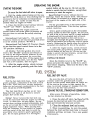
OPERATING
THE ENGINE
STARTING THE ENGINE
control button all the way in. Do not use thechoke
to enrich the fuel mixture, except when
necessary to start the engine.
Be sure the fuel shut-off valve is open.
2. Pull the choke control button all the way
out (see Illust. 3 or 4). More or less choking may be
necessary due to variations in temperature,
grade of fuel, etc. Little or none will beneeded
when the engine is warm.
Manual Starting: (Tractors without electric
starting). Raise the tractor hood. The retract-
able starter is mounted on a support plate at
the front of the engine at the right side of thetractor.
Put the gearshift lever in the neutral posi-
tion and lock the brake. Turn the key ignition
switch clockwise.
3. Place the throttle lever halfway between
"SLOW" and "FAST". See Illust. 3 or 4.
4. Electric Starting: The engine cannot be
started unless the brake pedal is pressed all
the way down to activate the safety starting
switch.
Give a quick steady pull on the retractable
starter handle to start the engine. Do not jerk.
or pull it out to its very end in a rough manner.
A steady pull will accomplish just as much.
Always pull the handle so the cord is in a
straight line through the guide. Maintain your
hold on the handle and allow the cord to return
slowly. Releasing the handle when the cable is
extended will shorten the life of the starter.
International Cub Cadet 71, 102, and 122
Tractors: Check to see that the gearshift leveris
in the neutral position. See Illust. 3.
International Cub Cadet 123 Tractor: Check
to see that the speed control lever is in the
I'N'I position. See Illust. 4.
All Models: Turn the ignition key clock-wise
to the "START" position and release it
as soon as the engine starts; however do not
operate the motor-generator for more than
30 seconds at anyone time. If the engine does
not start within this time, turn the key !'OFF"
and wait a few minute s. then try again.
5. After the engine starts, slowly release
the clutch pedal and gradually push the choke
control button all the way in. Do not use the
choke to enrich the fuel mixture, except when
nece s sa ry to start the engine.STOPPING
THE ENGINE
Move the throttle lever to the "SLOW" po-
sition and allow the engine to idle for a shorttime
before stopping. Then turn the key to the
"OFF" position.
5. After the engine starts. slowly releasethe
brake pedal and gradually push the choke
FUEL SHUT.OFF VALVE
FUEL
SYSTEM
Be sure the shut-off valve on the fuel
strainer under the gasoline tank is open.
Screw out the needle stem (Shut-off valve) un-
til the seat on the stem is tight against the
stop, to prevent leakage or seepage when the
valve is in its full-open position.
Fill the fuel tank with clean, fresh, regular
grade gasoline, preferably at the end of each
day's use. This will force out any moisture-
laden air and prevent condensation in the fueltank.
Do not mix oil with the gasoline.
CLEANING
THE FUEL STRAINER AND SEDIMENT BOWL
The fuel tank filler cap has an air vent.
Keep the vent open at all times to assure
proper flow of the fuel.
After every 25 hours of operation, cleanhe
fuel strainer as follows:
Caution! Never remove the fuel tank cap
or fill the fuel tank when the engine is running,
is hot, or when near an open flame. Do not
smoke when working around inflammable fuel,as
the air around the tractor is mixed with a
highly explosive vapor. When pouring fuel,
keep the container or hose nozzle in contact
with the metal of the fuel tank to avoid the
possibility of an electric spark igniting the
gas. Do not spill gasoline on a hot engine.
1. Close the shut-off valve. See Illusts.7 and 7A).
Loosen the knurled nut under the sediment
bowl and remove the bowl and screen.
2.
Clean the sediment bowl and screen.
3. When reassembling, be sure the gasket
between the bowl and the main body is in good
condition and does not leak. Use a new gasket
if necessary.
6

FUEL SYSTEM
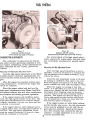
Illust. 7
Carburetor and fuel strainer.
(International Cub Cadet 71 Tractor)
Illust.7A
Carburetor and fuel strainer.
(Internationol Cub Cadet 102, 122 and 123 Tractors)
CARBURETOR ADJUSTMENTS
For a final check of the high speed adjust-
ment, operate the engine under load and make
any corrections necessary for smooth opera-
tion.
Adjusting the Idle Adjustment Screw
The carburetor is adjusted at the factory
and under normal operating conditions it will
not require readjusting. If this adjustment has
been disturbed for any reason, proceed as
follows:
Adjusting the High-Speed Adjustment Screw
After the high speed adjustment screw is
adjusted, it may be necessary to readjust the
idle adjustment screw (1IIusts. 7 and 7A), as each
affects the other.
Turn the high speed adjustment screw (1IIusts.
7 and 7A) counter-clockwise approximately two
turns from the closed position and start the en-gine.
Close the idle adjustment screw to its seat
by turning it clockwise; then open it one turn.
Start the engine and operate it at fast idling
speed (without any load) until thoroughly warm.
After the engine has reached normal oper-
ating temperature, accelerate the engine and
check its response.
While the engine is running at fast idle
speed, it is advisable to screw in the throttle
stop sc rew (1IIusts.7 and 7 A) a few turns to keep
the engine from stopping when the throttle
lever is moved to the fully retarded "SLOW"
position. The engine will then be idling at a
fairly high speed and the throttle stop screw
can be backed out a little at a time until the
desired idle speed is obtained.
Place the engine under load and turn the
high speed adjustment screw (1IIusts. 7 and 7A) to
the leanest mixture that will allow satisfactory
acceleration and steady governor operation.
If the engine misses and backfires under
load, the high speed mixture is too lean. The
high speed adjustment screw must be turned
counte r- clockwise 1 /4 turn at a time until the
condition is corrected.
If the engine misses or rolls while backing
out the throttle stop screw. the idle adjustment
screw may be adjusted in or out until the en-
gine operates smoothly. Speed up the engine
for a few seconds; then recheck the idle ad-
justment. A slight adjustment in or out will
give the smoothest idle.
If the engine shows a sooty exhaust and is
sluggish under load, the high speed mixture is
too rich. The high speed adjustment screw
must be turned clockwise 1 /4 turn at a time
until the condition is corrected.
7

PREPARING THE TRACTOR FOR EACH DAY'S WORK
Fill the fuel tank at the end of each day's
run. See page 6.
Check the crankcase oil level and add new
oil if necessary. Seepage 26.
Clean the air cleaner element if necessary.
See page 14.
Inspect the tires for general condition. See
pages 20 and 21.
ADJU STING THE SEAT
Illust. SA
Adjusting the seat.
(International Cub Cadet 102 Tractor.)
Illust. 88
Adju sting the seat.
(Internatianal Cub Cadet 71 Tractar.)
Illust. 8
Adjusting the seat.
(Intemational Cub Cadet 122 and 123 Tractors)
Before starting the tractor, adjust the seat
to the most comfortable driving position by
loosening the four cap screws in the seat sup-
port (II lust. 8) or seat bracket (1IIust. 8A) or seat
spring clamping plate (1IIust.88) and sliding the
seat assembly forward or rearward to the
position which is most comfortable for theoperator.
Retighten the cap screws after the seat is
adjus ted.
The International Cub Cadet 122 and 123
Tractors features a seat which can be tilted
forward over the steering wheel, for conven-
ience in adjusting the seat and to keep out
rain and snow. See Illust. 8.
Illust. 8C
Brake pedal lack in the engaged position.
8

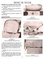
DRIVING THE TRACTOR
(International Cub Cadet 71, 102 and 122 Tractors)
CLUTCH AND BRAKE PEDAL
Note: Do not rest your foot on the pedalwhile
driving the tractor, as this will result
in excessive clutch lining wear.
The combination clutch and brake pedal is
used to disengage the engine from the trans-
mission when shifting gears and to actuate the
brake to stop the tractor. The pedal must be
pressed all the way down to activate the safety
starting switch when starting the engine.
Always be sure the rear wheels are free
to turn. Under any adverse conditions, do not
attempt to free the tractor by speeding up the
engine and suddenly engaging the clutch. Try
backing out instead of going forward.
To disengage the clutch, press the pedal
approximately half way down. To stop the trac-
tor press the pedal all the way down.
STOPPING THE TRACTOR
Disengage the clutch by pressing the pedal
all the way down. Move the gearshift lever to
the neutral position.
LOCKING THE BRAKE
CREEPER SHIFT LEVER
Always lock the brake when the tractor is
parked on a grade. To lock the brake, press
down on the brake pedal; ther. place the brake
pedal lock in the engaged position. To disen-
gage the lock, press down on the brake pedal
lift the lock up and place it in the disengagE:d
position behind the brake pedal as shown in
Illust. 17A.
The creeper drive provides a slower speed
in each respective gear, by a four-to-one re-
duction in speed from direct drive. When the
creeper shift lever is all the way forward, it
is in direct drive, or all the way rearward, it
is in creeper drive. See Illust. 3. Note: Do not
use a mid-point position on the creeper driveas
neutral. Neutral position must be selected
only with the standard transmission gearshift
lever.
GEARSHIFT LEVER
OPERATING THE CREEPER DRIVE
To operate the tractor in creeper drive,
move the creeper shift lever (1IIust.3) all the
way rearward. Then select the speed desired
and proceed as instructed under "Starting the
Tractor".
This lever is used to select various gear
ratios provided in the transmission. There
are three forward speeds and one reverse
speed. See Illust. 3. Refer to "SPECIFICA TlaNS't
on page 32.
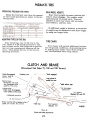
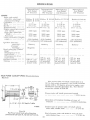
The following table shows the speeds avail-
able in each of the three forward gears and thereverse
gear.
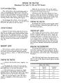
STARTING THE TRACTOR
1. Advance the th rattle leve r s lightly. SeeIllust.
3.
Miles
Per Hour
2. Disengage the clutch by pressing the
clutch pedal all the way down, and move the
gearshift lever to the desired speed.
Creeper
Drive
Direct
Drive
Gear
3. Start the tractor in motion by slowly
releasing the clutch pedal and moving thethrottle
lever to the pos it ion where the engine
operates best for the load to be handled.
First
2.3
.6
Second
3.9
1.0
6.8
Third
1.7
Note: Do not shift gears while the engine
clutch is engaged or while the tractor is inmotion.
Reverse
2.5
.6
a

DRIVING THE TRACTOR
(International Cub Cadet 123 Tractor)
Hote: Do not rest your foot on the brake
pedal while driving the tractor as this wouldcause
the speed control lever to return to the
"N" position.
BRAKE PEDAL
The brake pedal must -be pressed all the
way down to activate the safety starting switch.
When the brake pedal is in the depressed posi-
tion it automatically moves the speed control
lever to the "N" position.
$T ARTING THE TRACTOR
The tractor can be stopped either by
pressing the pedal all the way down, or placing
the speed control lever in the "N" position.
See
1. Advance the throttle lever slightly.
1!lust.4.
LOCKING
THE BRAKE
2. Depress the brake pedal by pressing the
pedal all the way down, and move the towing
lever (lllust. 4) in drive (horizontal) position,
then move the throttle lever to the position
where the engine operates best for the load to
be handled.
Always lock the brake when dismounting
from the tractor. To lock the brake, press
down on the brake pedal; then place the brake
pedal lock in the engaged position. See Illust. 8C.
To disengage the lock, press down on the brak",
pedal, lift the lock up and place it in the dis-
engaged position behind the brake pedal as
shown in Illust. 17A.
3. Start the tractor in motion by moving
the speed control lever forward or rearward
as described above.
SPEED CONTROL LEVER
This lever is used to select any speeds
from a standstill "NI! position to eight miles
per hour in the forward direction and to fourmiles
per hour in the reverse direction.
RELEASE LEVER
To push or move tractor for a short distance
or when working on the engine. the release le-
ver (1!lust.4) must be locked in the release
(down) position and the speed control lever must
be in the 'IN'I position. Caution: 12.2 tlQ.t;. ~.
STOPPING THE TRACTOR
Moving the speed control lever forward
provides increased forward speeds, and mov-
ing the lever rearward provides the reversedspeeds.
Move the speed control lever to the I'NII
position or use the brake. Before dismounting
always depress the brake pedal.
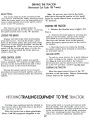
TRAILING
EQUIPMENT TO
THE
Trailing -type equipment must be hitched to
the tractor only at the hitch hole in the draw-bar.
See Illusts. 11 and 11A.
three-point hitch is raised and lowered with
the lift handle. The lift handle can be set tohold
the equipment at various positions by use
of the six notches in the lift handle quadrant.
The lower mounting bracket has three holes
which are used for additional adjustment.
When the tractor has a three-point hitch
(1IIusts. 11 and 11A) equipment adaptable to the
10

HITCHING TRAILING EQUIPMENT TO THE TRACTOR
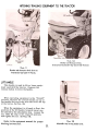
Illust. 11A
Drawbar and three-paint hitch.
(International Cub Cadet 102. 122 and 123 Tractors)
Illust. 11
Drawbar and three-point hitch shown on
International Cub Cadet 71 Tractor.
LIFT HANDLE
This handle is used to lift or lower equip-
ment used with the tractor. Depress the
release button to move the handle.
When operating equipment in the "FLOAT"
position, depress the release button on top of
the handle and move the wire bail over the top
of the button. See Illust. 118.
When the equipment is allowed to float, the
position of the lift handle forward travel can
be limited by the adjustable stop. Loosen the
nut, slide the stop to the required position,
and tighten the nut. See Illust. 118.
Refer to the equipment manual for properhitching
instructions.
Illust. 118
Adjustable stop limiting handle travel.
11

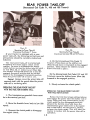
REAR POWER TAKE-OFF
(International Cub Cadet 71, 102 and 122 Tractors)
Illust. 12
Operating the Pawer T ake.aff.
Internatianal Cub Cadet 71 Tractar
Itlust.12A
Operating the Pawer Take-off.
Internatianal Cub Cadet 102 and 122 Tractars
If your tractor is equipped with a rear
power take-off, the following instructions and
precautions should be carefully studied and
followed.
The rear power take-off is started and
stopped by the same engine clutch as the
tractor. Be sure to disengage the engine
clutch before moving the power take-off shift -
er rod (1IIust. 12), or shifter lever (1IIust. 12A).
The shifter rod should always be in the dis-
engaged (forward) position and the shifter
lever in the disengaged (rearward) position
when the power take-off is not in use.
4. On the Inte rnational Cub Cadet 71
Tractor; Press down on the shifter rod
(1IIust. 12) and move it rearward to the engaged
position. Then release the shifter rod and
allow it to lock in place.
On the International Cub Cadet 102 and 122
Tractors; move the shifter lever (1IIust.12A)
forward to the engaged position.
Caution! Always cover the power take-off
exposed shaft with the guard when the power
take-off is not being used.
5.
Slowly release the clutch pedal.
OPERATING THE REAR POWER TAKE.OFF
WITH THE TRACTOR STANDING STILL
OPERATING THE REAR POWER TAKE.OFF
WITH TRACTOR IN MOTION
1. The transmission gearshift lever mustbe
in the neutral position.
2. Move the throttle lever back to low idlespeed.
Follow the first four steps outlined above;
then engage the power take-off shifter rod or
lever. Keep your foot pressed down on the
clutch pedal (in the dis engaged position),
advance the throttle lever and move the
transmission gear-shift lever to the speed
that is desired to run the tractor. Slowly
release the clutch pedal. This will start the
tractor in motion with the power take-off in
operation.
3. Depress the clutch pedal to disengage
the engine clutch.
12

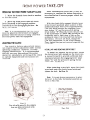
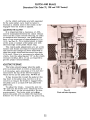
OPERATING THE FRONT POWER TAKE.OFF CLUTCH
After considerable clutch use, it may be
necessary to readjust the button clearance as
described below to assure proper clutch dis-
engagement.
1. Move the throttle lever back to medium
or low idle speed.
2. Move the front power take-off clutch
lever (forward) to the engaged position
(rearward) to the disengaged position. See
Illusts. 3 or 4 ond 13A.
Note: It is recommended that the clutch
lever be placed in the forward or engaged
position when the tractor is being used with-
out front power take-off equipment.
With the clutch fully engaged (clutch lever
in the forward position) place a piece of thin
cardboard (match book cover) approximately
1/64 inch thick between the engaging lever
wear button IIAII and the pressure spring
thrust button IIBII (1IIust. 13), loosen the jam nut
on the turnbuckle lIC't (1IIust. 13A), and adjust the
turnbuckle until a light drag is felt on the
cardboard when it is removed from between
the buttons. Be sure all slack, except the
1/64 inch adjustment, is out of the linkage.
Then, tighten the jam nut securely against the
turnbuckle.
ADJUSTING THE CLUTCH
INSTALLING AND REMOVING DRIVE BELT
To install or remove the drive belt, loosen
the clutch lever bolt enough so the lever can
be moved forward to provide sufficient belt
clearance between the engaging lever wear
button "A" and the pressure spring thrust
button "B", s..lllust.13.
The clutch is factory adjusted and should
not require further adjustment under normal
operating conditions. However, if clutch
slippage should occur. It is recommended
that you see your International Harvester
dealer for satisfactory servicing of the clutch,
as special equipment and instructions are
required.
After installing a new belt, move the clutch
lever back onto the clutch lever latch and
tighten the bolt. See Illust. 13.
Note: It is not always necessary to place
the lever in the fully horizontal position as
shown in Illust. 13A.
Illust. 13
View with grille removed to show engoging
lever weor button ond pressure spring
thrust button.
Illust. 13 A
13

ENGINE COOLING
This tractor has an air cooled engine. Air
must be able to circulate freely around the
engine, through the screen and shroud, and
over the fins of the cylinder head and cylinderblock.
Keep these areas free of accumulated
dirt and trash or the engine will overheat and
result in damaged moving parts.
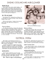
DRY-TYPE AIR CLEANER
Incoming air for combustion is filtered by
a dry-type air cleaner having a filter element
inside of the cover.
Remove and clean or replace the element
with a new one when loss of power isnoticeable.
Illust. 14
Removing the air cleaner filter element.
Cleaning the Element
Replacing the Element
To clean the element. remove the wing nut
and air cleaner cover (1IIust. 14) then remove the
element and tap it lightl y on a flat surface to
cause the loose dirt to falloff. Handle the
paper element with care to avoid perforations.Do
not use compressed air to remove the dirt
as this can rupture the element. Do not wash
or use a solvent.
Replace the element with a new one if dirt
does not drop off easily or if it is bent,crushed
or damaged. When replacing the ele-
ment be sure it fits snugly around the insideedge
of the air cleaner base. Then replace the
cover and tighten the wing nut finger tight.
The twelve-volt electrical system on a
tractor with electric starting consists princi-
pally of a motor-generator, voltage regulator,
and a twelve-volt battery.
the
engine has stalled and the operator leaves
the tractor, the key must be turned to the
"OFF" position to prevent battery discharge.
Use the illustrations on poge 17 and wiringdiagrams
on poge 18, as a guide for identifyingthe
various electrical units and for tracing the
electrical cables and connections. Be sure all
connections are clean and securely fastened.
SAFETY STARTING SWITCH
The safety starting switch, activated by the
clutch or brake pedal, serves to prevent start-
ing the engine accidentally.
LIGHTING SWITCH BUTTON
IGNITION SWITCH
Pull the button (1IIust. 17A) out to turn on thelights
and push it in to turn off the lights.
Turn the key clockwise to turn on the
ignition. With electric starting, a further turn
actuate s the motor -generator. The key cannot
be removed when in the IIONtl position.
CIGARETTE LIGHTER
Push the lighter to make electrical contact.
When it pops back it is ready for use.
Note: When the engine is not operating or
14

ELECTRICAL SYSTEM
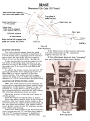
SPARK PLUG
IGNITION TIMING
Note: Remove all dirt from the base of the
spark plug before removing the spark plug.
Remove the spark plug after every 100
hours of operation for cleaning and checking
the gap. See Illust. 15. When making this adjust-
ment, always bend the outer electrode. Never
bend the center electrode, as it may damag:!
the insulator. If the gap between the electrodes
is too great, the engine will misfire and be
hard to start.
Always use a spark plug wrench when re-
moving or reinstalling the plug.
Illust.15A
Adjusting the breaker paints.
Set gap at .O20-inch.
Be sure the gasket is in good condition,
and screw the plug in tightly. Do not tighten
more than enough to compress the gasket to
seal the plug and assure a good heat transfer
between the plug and the cylinder head. Tighten
the plug 1/2 to 3/4 turns past finger tight.
Remove the breaker point cover after every
100 hours of operation for cleaning the points
and resetting the gap (1IIust.15A). Replace badly
pitted or burned points.
For more precise timing, a timing light
should be used. The engine has a timing sight
hole which is located in the right s ide of the
engine bearing plate on the International Cub
Cadet 71 Tractor or in the right side of the
blower housing in the International Cub Cadet
102, 122 and 123 Tractors. See Illust.15B.
With the engine running at 1/3 throttle. or
more, adjust the breaker points until the "SP"
mark on the flywheel is centered in the sight
hole. Note: The "Spl' mark will appear 20degrees
before top dead center. The other
mark is the top center mark and is stamped
with "DC'I below the mark.
(Ilust. 15
Checking the spark plug gap.
Set gap at .O25-inch.
Replace a defective plug with a new plug.
See your International Harvester dealer for a
correct replacement plug.
Cleaning the Spark Plug
Sandblasting is the recommended method of
cleaning the spark plug. Never scrape or clean
the insulator with anything which will scratch
the porcelain. Scratched porcelain allows
carbon and dirt to accumulate much faster.
Illust. 158
Location of timing sight hole.
(Motor-generotor has been removed to better
illustrate the location).
15

ELECTRICAL SYSTEM
MOTOR-GENERATORRemoving
and Replacing the Motor-Generator Belt
Replace the motor-generator belt when it
becomes badly worn. To remove the old belt,
loosen the motor-generator brace bolt I'A" and
mounting bolt.s lIB", Illust.17. Move the gener-
ator in toward the engine and slip the old belt
off the pulleys and over the crankshaft. Install
the new belt in the reverse order of removal
and adjust the belt to the proper tension.
The motor-generator (IZ-volt, negative
ground) will function as a cranking motor when
the ignition key is turned to the "START"
position, driving the engine by means of abelt.
When the engine is operating, the unit will
function as a generator.
MOTOR-GENERATOR BELT
VOL TAGE REGULATOR
Check the tension of the motor -generator
belt after the first 10 hours of operation and
every 50 hours of operation thereafter. The
tension is correct when the belt can be
deflected a maximum of 1/4-inch by a ten
pound force applied midway between the two
pulleys.
A satisfactory generator charging rate is
maintained by the voltage regulator. If the
regulator fails to operate correctly, see your
International Harvester dealer.
Hote: Never place a jumper lead between,
or accidentally bridge, the I'BAT'I terminal
and the I'FI' terminal on the regulator, as this
will damage the regulator.
LIGHTS
The headlights are sealed-beam lights. The
parts are so constructed that the filament, re-
flector, and lens are all assembled in a unit
permanently sealed against dirt, moisture,
and corrosion. If a filament burns out or a
lens bxeaks, the complete unit must be re-
placed. Refer to I'SPECIFICA TIONS".
TAilliGHT
To replace the taillight lamp, remove thelens
from the taillight and replace the taillight
lamp with a 4 candle power lamp. Refer to
"SPECIFICATIONS".
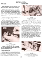
FUSE (Electric Lighting)
Also follow this procedure when a new beltis
installed.
Adjusting the Motor-Generator Belt
It is important to use the same capacity
fuse for replacement. Refer to "Specifica-
tions". If the lights fail. check the fuse. If a
fuse continually burns out. check the electri-
cal wiring for short circuits.
Loosen the motor-generator brace bolt I'A'I
and mounting bolts IIBI', Illust.17.
Move the generator away from the engine
until the tension on the belt is correct. See
Illust. 16.
The fuse is located in a fuse housing in theline
at the back of the instrument panel. See
Illust. 18.
Note: Under no circumstances should a pry
bar.be used on the motor-generator to obtain
belt tension as damage to the bearings will
re suIt.
To install a new fuse. pre ss in on the fusehousing
cap and turn counterclockwise to re-move
it from the fuse housing. Remove the oldfuse
and replace it with a new one. Then re-
assemble the cap to the housing. Remove the
battery if necessary to reach the fuse.
Tighten mounting bolts IIB'I and brace bolt
IIA II
16

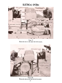
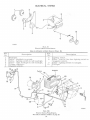
ELECTRICAL SYSTEM
Illust. 17
Electrical units an the right side of the tractor.
Illust.17A
Electrical units on the left side of the tractor.
17

Page is loading ...
Page is loading ...
Page is loading ...
Page is loading ...
Page is loading ...
Page is loading ...
Page is loading ...
Page is loading ...
Page is loading ...
Page is loading ...
Page is loading ...
Page is loading ...
Page is loading ...
Page is loading ...
Page is loading ...
Page is loading ...
Page is loading ...
Page is loading ...
Page is loading ...
Page is loading ...
-
 1
1
-
 2
2
-
 3
3
-
 4
4
-
 5
5
-
 6
6
-
 7
7
-
 8
8
-
 9
9
-
 10
10
-
 11
11
-
 12
12
-
 13
13
-
 14
14
-
 15
15
-
 16
16
-
 17
17
-
 18
18
-
 19
19
-
 20
20
-
 21
21
-
 22
22
-
 23
23
-
 24
24
-
 25
25
-
 26
26
-
 27
27
-
 28
28
-
 29
29
-
 30
30
-
 31
31
-
 32
32
-
 33
33
-
 34
34
-
 35
35
-
 36
36
-
 37
37
-
 38
38
-
 39
39
-
 40
40


Ask a question and I''ll find the answer in the document
Finding information in a document is now easier with AI
Related papers
Other documents
-
 International Harvester Company Cub User manual
-
LEE DING LD-O01361 User manual
-
 Aimco Brakes Model 70 User manual
-
Sears 917.25041 Owner's manual
-
Draper Mechanic's Creeper Operating instructions
-
Barska AF12544 Owner's manual
-
MyBinding Tamerica 240Epb Heavy Duty Electric Comb Binding Machine User manual
-
-
Harbor Freight Tools 40 in. 300 lb. Capacity Low_Profile Creeper User manual
-
 International Harvester Company McCormick Farmall Super C User manual


