Page is loading ...


have difficulties with the unit consult your
International Harvester dealer. UNDER NO CIR-
CUMSTANCES SHOULD YOU ATTEMPT TO
SERVICE THESE UNITS YOURSELF. Only your
dealer is authorized to repair or replace units on
this drive under the terms of the warranty. Should
you desire additional information not found in this
manual, contact your International Harvester
dealer.
Assembled in this manual are operation, lubri-
cation, and maintenance instructions for the
International Cub Cadet 86, 108, 128, 129, 149,
and 169 Tractors. The material has been prepared
in detail to help you better understand the correct
care and efficient operation of your tractor. Before
you operate the tractor, study this manual care-fully.
New copies may be ordered from your dealer
at a nominal price.
The I nternational Cub Cadet 86, 108, and 128
...
Your local I nternational Harvester dealer is inter-
ested in the performance you receive from this
tractor. He has factory-trained servicemen, in-
formed in the latest method of servicing tractors,
modern tools, and original-equ ipment I H service
parts which assure proper fit and good perfor-
mance.
To obtain top performance and assure economical
operation the tractor should be inspected, depend-
ing on its use, periodically, or at least once a year,
by your International Harvester dealer.
The International Cub Cadet 129, 149, and 169
Tractors have a hydrostatic drive. It is the best
hydraulic drive unit available and will require
minimum service if recommended operation and
maintenance procedures are followed. Should you
When in need of parts, always specify the model,
chassis, and engine serial numbers, including the
prefix and suffix letters. Write these serial numbers
in the space provided on page 4.
Tractors have a conventional clutch ana trans-
mission.


MODEL
DELIVERY
DATE
Serial No. 500718 and above.
LEFT and RIGHT indicate the left and right sides
of the tractor when facing forward in the driver's
seat. Reference to F RaNT indicates the grille end
of the tractor; to REAR the drawbar end.
A variety of extra equipment and accessories isavailable.
Where operating and maintaining instruc-
tion is required, it is included in the instruction for
operating and maintaining the tractor. Disregard
the instructions for equipment not on your tractor.
This manual is for tractors with Serial No. 507 000 and above.
4

This symbol is used to call your attention to instructions
concerning your personal safety. Be sure to observe and
following these instructions.
Disengage all clutches and shift into neutral before
starting the engine.
Use care when pulling loads or using heavy
equipment: -A. Use only approved hitch points.
B. limit loads to those you can safety control.
C. Don't turn too sharp, and use care when
backing. D. Use counterweight or wheel weights
when suggested in Operator's Manual.
Disengage power to any attachments and stop
engine before leaving operator's seat or making any
repairs or adjustments.
Know the controls and how to stop quickly -
READ THE OPERATOR'S MANUAL.
Watch out for traffic when crossing or near
roadways.
Do not allow children or adults to operate the
equ ipment without proper instruction.
When using any attachments, never direct discharge
of material toward bystanders nor allow anyone
near the machine while in operation.
Clear work area of objects which might be picked
up and thrown.
Handle gasoline with care -it is highly flammable:
-A. Use approved gasoline container. B. Never
remove the fuel tank cap or fill the fuel tank when
the engine is running, is hot, or indoors. Also, do
not smoke when working around inflammable fuel.
Wipe up spilled gasoline. C. Replace gasoline cap
securely. D. Open doors if engine is running in a
garage -exhaust gases are dangerous.
Disengage power to any attachment when trans-
porting or not in use.
Do not carry passengers of give rides. Keep child-
ren, pets, and by-standers a safe distance away.
Always disengage the power take-off, shift trans-
mission into neutral, set the parking brake, stop
the engine, and remove ignition key when leaving
the machine unattended.
Keep machine in good operating condition and
keep safety devices in place. Use guards or shields
as instructed in Operator's Manual.
Reduce speed on slopes and in sharp turns to
prevent tipping or loss of control.
It is recommended that the machine be stopped
and inspected for damage after striking a foreign
object and that any damage be repaired before
restarting and operating the machine.
Stay alert for holes in terrain and other hidden
hazards.
Always depress the brake pedal and set the brake
pedal lock before working on the machine. Dis-
engage all implements and shift the transmission
into neutral.
Don't stop or start suddenly when going uphill ordownhill.
5

Your Cub Cadet Tractor has been safety engineered. Thoroughly
acquaint yourself with all the instruments and controls before
attempting to start or operate the tractor.
Instruments and controls on the International Cub Cadet 86, 108, and 128 Tractors.
1. Brake pedal lock 2. Choke control button. 3. Clutch-brake pedal 4. Creeper shift lever* 5. Front power take-off clutch lever. 6. Gearshiftlever 7. Lift handle cam stop 8. Lighting switch button* 9. Ignition switch """"""""" 10. Throttle 11. Electricliftcontrolswitch* 12. Charge indicator """""""'-:":'--""""
* Optional Equipment
6
See page 12
See page 9
See pages 12 and 13
See page 13
See page 18
See page 13
See page 15
See page 21
See page 8
See page 18 and 19
See page 22

Instruments and controls on the International Cub Cadet 129, 149, and 169 Tractors.
See page 14
See page 14
See page 14
See page 9
See page 18
See page 22
See page 20
See page 8
See page 21
See page 15
See page 15
See page 22
1. Brake pedal lock 2. Brake pedal. 3. Speed control lever 4. Choke control button 5. Front power take-off clutch lever 6. Charge indicator : 7. Hydraulic lift control handle 8. Throttle lever 9. Ignition switch. 10. Lighting switch button* (Standard on Models 149 and 169) 11. Lifthandlecamstop 12. Release lever. 13. Hour meter- (Standard on Model 169 only) Electrict lift* (Not shown.) Available on all but the
Model 149 and 169 Tractors.
* Optional Equipment
7

Lubricate the entire tractor. See pages 33 to 41
Lubrication
Check the air pressure. See pages 24 to 26
Tires.
Fuel System. Fill the fuel tank with gasoline. See pages 10 and 11.
4.
Fuel line
5. Fuel shut-off valve
6. Air cleaner
1. Fuel tank filler cap
2. Fuel tank
3. Carburetor (not seen)
Fuel System.
THROTTLE LEVER
GOVERNOR
This lever controls the speed of the engine. When
set in a given position, it will maintain a uniform
engine speed.
The governor is set at the time the engine is
assembled and should not require readjustment
unless the governor arm is removed or loosened
from the governor shaft. Consult your
I nternational Harvester dealer if the governor does
not function properly.
When using power take-off operated equipment,
best performance is achieved with the throttle lever
in the "FAST" position.
8

OPERATING THE ENGINE
LIFTING THE HOOD
3.
Pull the choke control button all the way out.
More or less choking may be necessary due to
variations in temperature, grade of fuel, etc. Little
or no choking will be needed when the engine iswarm.
The tractor hood is arranged to swing up and
forward to make the engine and fuel tank readily
accessible. To raise the hood take hold of the
spring latches on each side of the pedestal and lift
up and out to release the spring latches from the
hood crossmember.
4.
Place the throttle lever half-way between
"SLOW" and "FAST",
5.
Place the throttle lever half-way between
"SLOW" and "FAST".
6. To start the engine the clutch-brake pedal must
be pressed all the way down and the power
take-off clutch handle must be in the disengaged
position to actuate the safety starting switches.
On the I nternational Cub Cadet 129, 149, and 169
Tractors the speed control lever will return to
neutral wher the clutch-brake pedal is pressed all
the way down.
International Cub Cadet 86, 108, and 128 Trac-
tors: Check to see that the gearshift lever is in the
neutral position.
All Models: Turn the ignition key clockwise to the
"ST ART" position and release it as soon as the
engine starts; however do not operate the motor
generator for more than 30 seconds at anyone
time. If the engine does not start within this time,
turn the key "OFF" and wait a few minutes, then
try again.
5. After the engine starts, slowly release the
clutch-brake pedal and gradually push the choke
control button all the way in. Do not use the
choke to enrich the fuel mixture, except when
necessary to start the engine.
STARTING THE ENGINE
1.
Be sure there is an adequate supply of gasoline
in the fuel tank.
STOPPING THE ENGINE
A CAUTION! Never remove the fuel tank
cap or fill the fuel tank when the engine
is running, is hot, or indoors. Also, do
not smoke when working around inflammable fuel.
Move the throttle lever to the "SLOW" position
and allow the engine to idle for a short time before
stopping. Then turn the key to the "OFF"
position.
2.
Be sure the fuel shut-off valve is open.
9

FUEL SYSTEM
This engine is designed to operate on leaded
gasoline with a 93 minimum octane rating or on
unleaded or low lead gasoline with a 91 minimum
octane rating (Research Method).
The
use of unleaded gasoline will lengthen spark
plug and valve life, maintain engine performance
longer, and reduce rust and corrosion of engine
wh ile stored.
The fuel tank filler cap has an air vent. Keep the
vent open at all times to assure proper flow of thefuel.
A CAUTION! Never remove the fuel tank cap
or fill the fuel tank when the engine is
running, hot, or when near an open flame.
Do not smoke when working around inflammable
fuel, as the air around the tractor is mixed with a
highly explosive vapor. When pouring fuel, keep
the container or hose nozzle in contact with the
metal of the fuel tank to avoid the possibility of an
electric spark igniting the gas. Do not spill gasoline
on a hot engine.
International Cub Cadet 86 Tractor.
FUEL SHUT-OFF VALVE
Be sure the shut-off valve under the fuel tank isopen.
Screw out the needle stem (shut-off valve)
until the seat on the stem is tight against the stop
to prevent leakage or seepage when the valve is in
its full-open position.
CARBURETOR ADJUSTMENTS
The carburetor is adjusted at the factory and under
normal operation conditions it will not require
readjusting. However, if the engine does not
operate properly, it is recommended a new air
cleaner be installed before performing carburetor
adjustments. If this adjustment has been disturbed
for any reason, proceed as follows:
1. Governor control rod2.
Idle adjustment screw3.
Throttle stop screw4.
High speed adjustment screw5.
Fuel shut-off valve6.
Fuel line7.
Air cleaner
International Cub Cadet 108, 128, 129,
149, and 169 Tractors.
10
~

FUEL SYSTEM
If the engine shows a sooty exhaust and is sluggish
under load, the high speed mixture is too rich. The
high speed adjustment screw must be turned
clockwise 1/4 turn at a time until the condition is
corrected.
CARBURETOR ADJUSTMENTS -Continued
A CAUTION! Be sure the brake pedal is in
the locked position, transmission is in
neutral, and the mower is disenga~d
before adjusting the carburetor.
Adjusting the Idle Adjustment Screw
Adjusting the High-Speed Adjustment Screw
After the high speed adjustment screw is adjusted,
it may be necessary to readjust the idle adjustment
screw as each affects the other.
Turn the high speed adjustment screw counter-
clockwise approximately two turns from the closed
position and start the engine.
Close the idle adjustment screw to its seat by
turning it clockwise; then open it one turn. Start
the engine and operate it at fast idling speed
(without any load) until thoroughly warm.
Be sure the choke is fully open when adjusting.
After the engine has reached normal operating
temperature, place the throttle lever in the fast
position and turn the high speed adjustment screw
clockwise to the leanest mixture that will allow
sat i sf actory acceleration and steady governor
operation. Then, turn counterclockwise to the
richest mixture that allows satisfactory operation.
The difference between the rich and lean points is
about 1/2 turn. Set the mixture to the rich end of
this range.
While the engine is running at fast idle speed, it is
advisable to screw in the throttle stop screw a few
turns to keep the engine from stopping when the
throttle lever is moved to the fully retarded
"SLOW" position. The engine will then be idling at
a fairly high speed and the throttle stop screw can
be backed out a little at a time until the desired
idle speed is obtained.
If the engine misses or rolls while backing out the
throttle stop screw, the idle adjustment screw may
be adjusted in or out until the engine operates
smoothly. Speed up the engine for a few seconds;
then recheck the idle adjustment. A slight adjust-
ment in or out will give the smoothest idle.
If the engine misses and backfires under load, the
high speed mixture is too lean. The high speed
adjustment screw must be turned counter-clock-
wise 1/4 turn at a time until the condition is
corrected.
PREPARING THE TRACTOR FOR EACH DAY'S WORK
Check the crankcase oil level and add new oil if necessary. See pages 34 and 35.
Clean the air cleaner element if necessary. See page 21.
Inspect the tires for general condition. See page 26
11

Retighten the cap screws after the seat is adjusted.
NOTE: The battery is located in a well under the
operator's seat for ease in servicing or replacement
when necessary.
CLUTCH AND BRAKE PEDAL
Brake pedal lock in the engaged position.
Adjusting the seat.
LOCKING THE BRAKE
Always lock the brake when the tractor is parked
on a grade. To lock the brake, press down on the
pedal; then place the brake pedal lock in the
engaged position. To disengage the lock, press
down on the pedal, lift the lock up and place it in
the disengaged position.
Before starting the tractor, adjust the seat to the
most comfortable driving position. Tile the seat
forward over the steering wheel, loosen the four
cap screws in the seat support, and slide the seat
assembly forward or rearward to the position
wh ich is most comfortable for the operator.
12

International Cub Cadet 86, 108 and 128 Tractors
CLUTCH-BRAKE PEDAL
free the tractor by speeding up the engine and
suddenly engaging the clutch. Try backing out
instead of going forward.
The combination clutch-brake pedal is used to
disengage the engine from the transmission when
shifting gears and to actuate the brake to stop the
tractor. The pedal must be pressed all the way
down to activate the safety starting switch when
starting the engine.
CAUTION!
Do not carry passengers or
give rides. Keep children, pets, and
bystanders a safe distance away.
STOPPING THE TRACTOR
To disengage the clutch, and apply the brake, press
the pedal all the way down.
Disengage the clutch by pressing the pedal all the
way down. Move the gearshift lever to the "N"
position. Before dismounting always lock the
pedal, disengage the power take-off, and turn the
ignition "OFF".
GEARSHIFT LEVER
This
lever is used to select various gear ratios
provided in the transmission. There are threeforward
speeds and one reverse speed. Refer to
"SPECIFICATIONS" on page 42.
CREEPER SHIFT LEVER
The creeper drive (optional) provides a slower
speed in each respective gear, by a four-to-one
reduction in speed from direct drive. When the
creeper shift lever is all the way forward, it is in
direct drive, or all the way rearward, it is in creeperdrive.
STARTING THE TRACTOR
1, Advance the throttle lever slightly.
2.
Disengage the clutch by pressing the clutch
pedal all the way down, and release the brake lock.
Move the gearshift lever to the desired speed.
OPERATING THE CREEPER DRIVE
3.
Start the tractor in motion by slowly releasing
the clutch pedal and moving the throttle lever to
the position where the engine operates best for the
load to be handled.
To operate the tractor in creeper drive, depress the
pedal and move the creeper shift lever all the wayrearward.
Then select the transmission speed de-
sired and proceed as instructed under "Starting the
Tractor".
NOTE: When using power take-off operated
equipment, best performance is achieved with the
throttle lever in the "Fast" position.
NOTE: Do not use a mid-point position on the
creeper drive as neutral. Neutral position must be
selected only with the standard transmission gear-
shift lever.
NOTE: Do not shift gears while the engine clutch
is engaged or while the tractor is in motion.
NOTE: Do not rest your foot on the pedal while
driving the tractor, as this will result in excessive
clutch lining wear.
The following table shows the speeds available in
Always be sure the rear wheels are free to turn.
Under any adverse conditions, do not attempt to
13
each of the three forward gears and the reversegear.

DRIVING THE TRACTDR
International Cadet 86, 108 and 128 Tractors
OPERATING THE CREEPER DRIVE
SPEED TABLE
Miles Per Hour
Creeper
Drive
Direct
Drive
Gear
.6
2.3
1.0
3.5
Second
1.7
6.8
.6
2.5
Reverse
International Cub Cadet 129, 149, and 169 Tractors
BRAKE PEDAL
The brake pedal must be pressed all the way down
to activate the safety starting switch. When the
brake pedal is in the depressed position it auto-
matically moves the speed control lever to the "N"
position.
NOTE: On tractors with a rotary tiller the follow-
ing instructions are required.
1. Engage the Power Take-Off clutch, and move
the throttle to "Fast".
The tractor can be stopped either by pressing the
pedal all the way down, or placing the speed
control lever in the "N" position.
2.
Lower the rotary tiller to the desired cutting
depth.
3.
Move the speed control lever to start forward
motion. NOTE: In rotary tilling application, the
tractor is used to hold the rotary tiller back rather
than to pull the unit as in plowing or mowing.
SPEED CONTROL LEVER
This lever is used to select any speed from a
standstill "N" position to eight miles per hour in
the forward direction and to four miles per hour in
the reverse direction.
4.
Move the speed control lever back to a position
to maintain proper mulching of the soil.
Moving the speed control lever forward provides
increased forward speed, and moving the lever
rearward provides the reverse speeds.
5. With a hydrostatic drive, it may be necessary to
vary the speed control lever as the soil conditionsvary.
With a gear driven tractor, under similar
conditions it may be necessary to declutch or to
use the brake.
NOTE: Do not rest your foot on the brake pedal
while driving the tractor as this would cause the
speed control lever to return to the "N" position.
14

DRIVING THE TRACTOR
International Cub Cadet 129, 149, and 169 Tractors
STARTING THE TRACTOR
CAUTION! Never operate engine with re-
lease lever in (up) position. Towing or
pushing the tractor for more than a few
feet may result in transmission damage.
1. Depress the brake pedal and release the brakelock.
Move the throttle lever to the position wherethe
engine operates best for the load to be handled.
STOPPING THE TRACTOR
2. Start the tractor in motion by moving the speed
control lever slowly forward or rearward as de-
scribed above.
Move the speed control lever to the "N" position
or use the brake. Before dismounting always lock
the brake pedal and turn the ignition "OF F", Also,
disengage the power take-off clutch lever.
RELEASE LEVER
To push or move the tractor for a short distance,the
release lever must be held in the (up) positionand
the speed control lever must be in the "N"
position.
CAUTION!
Do not carry passengers or
give rides. Keep children, pets, and
bystanders a safe distance away.
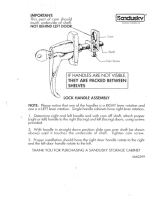
The lift handle is used to lift or lower equipment
used with the tractor. The equipment can be set in
multiple positions by depressing the button on the
top of the handle and releasing it when the desired
position is reached.
If free handle travel between cam stop and fully
raised position is desired (Float Position), depress
the release button on top of the handle, press in
the lock button located at the front of the handle
and release the top button.
HEIGHT ADJUSTMENT
If a single implement height is normally used, the
handle may be adjusted to locate the desired posi-
tion by use of the cam stop.
NOTE: To disengage the lift handle from the float
position, pull lift handle back slightly and depress
top button.
With lift handle in desired implement height posi-
tion, release cam by turning locking knob counter-clockwise.
Turn cam until it contacts tang. Lock
cam into this position by turning knob clockwise.
NOTE: Refer to the equipment manual for proper
hitching instructions.
15

1. Lift lever
2. Draw bar
3. Three-point hitch
Orawbar and three-point hitch shown
on International Cub Cadet 86 Tractor.
DRAWBAR
4. Cam lock knob
5. Cam stop
6. Tang
1. Release button2.
Lock button3.
Lift handle
Orawbar equipment must be hitched to the tractor
only at the hitch hole in the drawbar.
Adjustable stop limiting handle travel.
THREE-POINT HITCH
When the tractor has a three-point hitch, equip-
ment adaptable to this hitch is raised and lowered
with the lift handle or power lift control. The lift
handle can be set to hold the equipment at various
positions by use of the notches in the lift handle
quadrant or cam stop. The lower mounting bracket
has three holes which are used for additional
adjustment.
A CAUTION! Disengage power to any
attachment when transporting or not in
use.
NOTE: Refer to the equipment manual for proper
hitching instructions.
16

International Cub Cadet 86, 108 and 128 Tractors
1. Shifter lever
OPERATING THE REAR POWER TAKE-OFF
WITH THE TRACTOR STANDING STILL
1. Move the throttle lever back to the "SLOW"
speed.
2. Depress the pedal and move the transmission
gearshift lever to the neutral position.
1. Power take-off guard
2. Grease fitting
3.
Move the shifter lever forward to the engaged
position.
If your tractor is equipped with a rear power
take-off, the following instructions should be
carefully studied and followed.
4. Move the throttle lever forward to the "FAST"
position and slowly release the pedal.
The rear power take-off is started and stopped by
the same engine clutch as the tractor. Be sure to
disengage the engine clutch before moving the
power take-off shifter lever.
OPERATING THE REAR POWER TAKE-OFF
WITH TRACTOR IN MOTION
Follow steps 1 thru 3 outlined above. Keep the
pedal depressed, move the transmission gearshift
lever to the speed desired and advance the throttle
lever. Slowly release the clutch pedal. This will
start the tractor in motion with the power take-off
in operation.
A CAUTION! The shifter lever should always
be in the disengaged (rearward) position
when the power take-off is not in use.
Always cover the power take-off exposed shaft
with the guard when the power take-off is not
being used.
17

OPERATING THE FRONT POWER TAKE-OFF
CLUTCH
t. Move the throttle lever back to the medium or
"slow" position.
2. Move the control lever forward slowly to the
engaged position.
3.
Advance throttle to operating speed.
ADJUSTING THE POWER TAKE-OFF CLUTCH
1. Clutch lever bracket
2. Quick attachable cotter pin
3. Clutch lever rod
4. Clutch control handle
5. Turnbuckle
With the clutch fully engaged (clutch control
handle in the forward position) the clearance
between "A" and "B" should be minimal. When
disengaged, the plate "B" (with three legs) should
move a minimum of 1/10 inch to insure disengage-
ment. To adjust for proper clearance, loosen the
jam nut on the clutch lever turnbuckle, and adjust
the turnbuckle. After obtaining the proper clear-
ance tighten the jam nut securely against the
turnbuckle.
The clutch is factory adjusted and should not
require further adjustment under normal operating
conditions. However, if clutch slips or fails to
disengage, see your International Harvester dealer.
NOTE: Periodically lubricate the bushing in the
clutch lever bracket with a few drops of engine oil.
After considerable use, it may be necessary to
readjust the clutch to secure proper clutch engage-
ment.
A CAU!'ON! Do not adjust with engine
running.
The electric lift is a self-contained unit designed to
provide power with fingertip control for raising the
lowering mounted equipment.
The electric lift is available on all Cub Cadet
Tractors except the Models 149 and 169 wh ich is
equipped with a hydraulic lift as standard.
18
/