Drawmer Masterflow DC2496 Specification
- Category
- Video converters
- Type
- Specification
This manual is also suitable for

MasMas
MasMas
Mas
tt
tt
t
erer
erer
er
ff
ff
f
lolo
lolo
lo
ww
ww
w
DC2476
DIGITAL MASTERING PROCESSOR
COPYRIGHT
This manual is copyrighted 8 2001 by Drawmer Electronics, Ltd. With all rights reserved. Under copyright laws, no part of this publication
may be reproduced, transmitted, stored in a retrieval system or translated into any language in any form by any means, mechanical, opti-
cal, electronic, recording, or otherwise, without the written permission of Drawmer Electronics Ltd

2
ONE YEAR LIMITED WARRANTY
Drawmer Electronics Ltd., warrants the Drawmer DC2476 Dig-
ital audio processor to conform substantially to the specifica-
tions of this manual for a period of one year from the original
date of purchase when used in accordance with the specifica-
tions detailed in this manual. In the case of a valid warranty
claim, your sole and exclusive remedy and Drawmer’s entire li-
ability under any theory of liability will be to, at Drawmer=s discre-
tion, repair or replace the product without charge, or, if not possi-
ble, to refund the purchase price to you. This warranty is not trans-
ferable. It applies only to the original purchaser of the product.
For warranty service please call your local Drawmer dealer.
Alternatively call Drawmer Electronics Ltd. at +44 (0)1709
527574. Then ship the defective product, with transportation
and insurance charges pre-paid, to Drawmer Electronics Ltd.,
Coleman Street, Parkgate, Rotherham, S62 6EL UK. Write the
RA number in large letters in a prominent position on the ship-
ping box. Enclose your name, address, telephone number, copy
of the original sales invoice and a detailed description of the
problem. Drawmer will not accept responsibility for loss or dam-
age during transit.
This warranty is void if the product has been damaged by mis-
use, modification or unauthorised repair.
THIS WARRANTY IS IN LIEU OF ALL WARRANTIES,
WHETHER ORAL OR WRITTEN, EXPRESSED, IMPLIED OR
STATUTORY. DRAWMER MAKES NO OTHER WARRANTY
EITHER EXPRESS OR IMPLIED, INCLUDING, WITHOUT
LIMITATION, ANY IMPLIED WARRANTIES OF
MERCHANTABILITY, FITNESS FOR A PARTICULAR PUR-
POSE, OR NON-INFRINGEMENT. PURCHASER’S SOLE AND
EXCLUSIVE REMEDY UNDER THIS WARRANTY SHALL BE
REPAIR OR REPLACEMENT AS SPECIFIED HEREIN.
IN NO EVENT WILL DRAWMER ELECTRONICS LTD. BE LI-
ABLE FOR ANY DIRECT, INDIRECT, SPECIAL, INCIDENTAL
OR CONSEQUENTIAL DAMAGES RESULTING FROM ANY
DEFECT IN THE PRODUCT, INCLUDING LOST PROFITS,
DAMAGE TO PROPERTY, AND, TO THE EXTENT PERMIT-
TED BY LAW, DAMAGE FOR PERSONAL INJURY, EVEN IF
DRAWMER HAS BEEN ADVISED OF THE POSSIBILITY OF
SUCH DAMAGES.
Some states and specific countries do not allow the exclusion
of implied warranties or limitations on how long an implied war-
ranty may last, so the above limitations may not apply to you.
This warranty gives you specific legal rights. You may have
additional rights that vary from state to state, and country to
country.
In the interests of product development, Drawmer reserve the right to modify or improve specifications of
this product at any time, without prior notice.

3
Warranty . . . . . . . . . . . . . . . . . . . . . . . . . . . . . . . . . . . . . . . 2
Contents . . . . . . . . . . . . . . . . . . . . . . . . . . . . . . . . . . . . . . . 3
Safety Consideration . . . . . . . . . . . . . . . . . . . . . . . . . . . . . 4
Radio Frequencies Statement . . . . . . . . . . . . . . . . . . . . . . 4
Chapter 1 - DC2476 Digital Mastering Processor
Introduction . . . . . . . . . . . . . . . . . . . . . . . . . . . . . . . . . . . . 5
Audio Connections . . . . . . . . . . . . . . . . . . . . . . . . . . . . . . . 6
Installation Precautions. . . . . . . . . . . . . . . . . . . . . . . . . . . . 6
Installation and Connection Guide . . . . . . . . . . . . . . . . . . . . 7
Getting Started . . . . . . . . . . . . . . . . . . . . . . . . . . . . . . . . . 8
Chapter 2 - DC2476 Navigation
Finding your way around. . . . . . . . . . . . . . . . . . . . . . . . . . . 9
Effects Screen Navigation Map . . .. . . . . . . . . . . . . . . . . . 10
Chapter 3 - Control Key Overview
Patch . . . . . . . . . . . . . . . . . . . . . . . . . . . . . . . . . . . . . . . . 12
Global . . . . . . . . . . . . . . . . . . . . . . . . . . . . . . . . . . . . . . . 16
Control Keys . . . . . . . . . . . . . . . . . . . . . . . . . . . . . . . . . . 20
LED Display . . . . . . . . . . . . . . . . . . . . . . . . . . . . . . . . . . 20
Chain/ Param . . . . . . . . . . . . . . . . . . . . . . . . . . . . . . . . . . 21
Effects . . . . . . . . . . . . . . . . . . . . . . . . . . . . . . . . . . . . . . . . 21
Bypass . . . . . . . . . . . . . . . . . . . . . . . . . . . . . . . . . . . . . . . 21
Compare . . . . . . . . . . . . . . . . . . . . . . . . . . . . . . . . . . . . . 21
FX Bypass . . . . . . . . . . . . . . . . . . . . . . . . . . . . . . . . . . . . 21
FX Solo . . . . . . . . . . . . . . . . . . . . . . . . . . . . . . . . . . . . . . 21
Help . . . . . . . . . . . . . . . . . . . . . . . . . . . . . . . . . . . . . . . . . 21
Chapter 4 - Basic Effects
Introduction . . . . . . . . . . . . . . . . . . . . . . . . . . . . . . . . . . . . 22
Input . . . . . . . . . . . . . . . . . . . . . . . . . . . . . . . . . . . . . . . . . 25
Dynamic Equaliser and Full Band Compressor . . . . . . . . . 26
Equaliser . . . . . . . . . . . . . . . . . . . . . . . . . . . . . . . . . . . . . . 27
Expander . . . . . . . . . . . . . . . . . . . . . . . . . . . . . . . . . . . . . . 28
Bootstrap Compressor . . . . . . . . . . . . . . . . . . . . . . . . . . . 28
Limiter and Stereo Image . . . . . . . . . . . . . . . . . . . . . . . . . 29
3 Band Tube Saturation . . . . . . . . . . . . . . . . . . . . . . . . . . 29
Output . . . . . . . . . . . . . . . . . . . . . . . . . . . . . . . . . . . . . . . . 30
Cross-Over . . . . . . . . . . . . . . . . . . . . . . . . . . . . . . . . . . . . 31
Compare . . . . . . . . . . . . . . . . . . . . . . . . . . . . . . . . . . . . 31
Chapter 5 - Operation
. . . . . . . . . . . . . . . . . . . . . . . . . . . . 32
Chapter 6 - Information
Preset Factory Patches . . . . . . . . . . . . . . . . . . . . . . . . . . . 34
Midi Control Codes . . . . . . . . . . . . . . . . . . . . . . . . . . . 36
Chapter 7 - General Information
If a fault develops . . . . . . . . . . . . . . . . . . . . . . . . . . . . . . . 37
Contacting Drawmer . . . . . . . . . . . . . . . . . . . . . . . . . . . . . 37
Chapter 8 - DC2476 Data
Specification . . . . . . . . . . . . . . . . . . . . . . . . . . . . . . . . . . . 38
Block Diagrams . . . . . . . . . . . . . . . . . . . . . . . . . . . . . . . . . 39
CONTENTS

4
DRAWMER DC2476
DIGITAL MASTERING PROCESSOR
SAFETY CONSIDERATIONS
CAUTION - MAINS FUSE
TO REDUCE THE RISK OF FIRE REPLACE THE MAINS FUSE
ONLY WITH A FUSE THAT CONFORMS TO IEC 127-2.
250 VOLT WORKING, TIME DELAY TYPE AND BODY
SIZE OF 20mm x 5mm.
THE MAINS INPUT FUSE MUST BE RATED AT T500mA.
CAUTION - MAINS CABLE
DO NOT ATTEMPT TO CHANGE OR TAMPER WITH THE SUP-
PLIED MAINS CABLE.
CAUTION - SERVICING
DO NOT PERFORM ANY SERVICING. REFER ALL SERVICING
TO QUALIFIED SERVICE PERSONNEL.
WARNING
TO REDUCE THE RISK OF FIRE OR ELECTRIC SHOCK DO
NOT EXPOSE THIS EQUIPMENT TO RAIN OR MOISTURE.
For the USA
FEDERAL COMMUNICATIONS COMMISSION RADIO FREQUENCY IN-
TERFERENCE STATEMENT
This equipment has been tested and found to comply with the limits for a
Class B digital device, pursuant to Part 15 of the FCC Rules. These limits
are designed to provide reasonable protection against harmful interference
in a residential installation. This equipment generates, uses and can radiate
radio frequency energy and, if not installed and used in accordance with the
instructions, may cause harmful interference to radio communications. How-
ever, there is no guarantee that interference will not occur in a particular
installation. If this equipment does cause interference to radio or television
reception, which can be determined by turning the equipment off an on, then
the user is encouraged to try to correct the interference by one or more of
the following measures:
Re-orient or relocate the receiving antenna.
Increase the separation between the equipment and the receiver.
Connect the equipment into an outlet on a circuit different from that
to which the receiver is connected.
Consult the dealer or an experienced radio/TV technician for help.
Unauthorised changes or modification to this system can void the users=
authority to operate this equipment.
This equipment requires shielded interface cables in order to meet FCC
class B limit.
For Canada
CLASS B NOTICE
This digital apparatus does not exceed the Class B limits for radio noise
emissions set out in the Radio Interference Regulations of the Canadian
Department of Communications.
CLASSE B AVIS
Cet appareil numérique ne dépasse pas les limites de la classe B au niveau
des émissions de bruits radioélectriques fixés dans le Règlement des signaux
parasites par le ministère Canadien des Communications.

5
CHAPTER 1
DRAWMER DC2476 DIGITAL
MASTERING PROCESSOR
INTRODUCTION
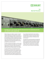
The Drawmer DC2476 is an extremely sophisticated, all-digital stereo
mastering processor designed for use in demanding recording and
broadcast applications. Both analogue (balanced XLR) and digital (AES/
EBU and S/PDIF) I/O is provided as standard. The audio converters are
24-bit and the digital output can be either 16, 18, 20 or 24-bit at sample
rates of up to 96kHz. Noise shaped dithering is included and Word Clock
input and output is available. A new feature is Output Trim which sets the
maximum level that output can reach, even in bypass, making the DC2476
easier to use in a broadcast environment.
Designed to be extremely easy and intuitive to use, the Drawmer DC2476
comprises a stage of dynamic equalisation, also incorporating full-band
compression (the DQ stage), followed by a five-band equaliser modelled on
the response of classic analogue filters. The signal is then split into three
user definable bands where it is routed via a three-band expander, a three-
band compressor, a three-band limiter and a three-band modelled tube
saturation stage. The three bands are then recombined before being fed to
the output stage via a fader system that can be used to generate precise
fade-ins and fade-outs of user definable length. The output stage itself offers
a number of dither options.
Although a wide range of manual control is provided, an automated gain
management system is used in addition to 'Programme Adaptive' time
constant management in the compressor and expander stages. The
automatic gain management monitors the signal level at critical points
throughout the signal chain and automatically reduces levels in situations
when overloads would otherwise occur. This makes the Drawmer DC2476
impossible to overload. Another key feature is the use of a 'Bootstrap'
compressor. Conventional compressors reduce the level of audio peaks, which
means make-up gain has to be applied to restore the same peak level. The
Drawmer DC2476 works the other way around by instead increasing the level
of quieter signals and leaving the peak levels at their original values.
This makes setting up far more intuitive when adjusting the individual bands
of a multi-band compressor and also avoids the necessity to juggle the
make-up gain control settings.
Why 96kHz?
Digital processing has until now been confined to 48kHz sampling frequency.
In order to achieve the required bandwidth for professional audio, a very
severe low pass filter at 23kHz is required to separate analogue signal
frequencies from the clock frequency otherwise unpleasant aliasing will occur.
This requires the use of a FIR digital filter which is part of the A/D and D/A
converters. Unfortunately these filters cause what is known as >time smear=,
where short transients are smeared over a longer time period giving loss of
HF detail. At 96kHz sample frequency, the low pass filter is less severe and
at twice the frequency, so time smear is considerably reduced.
A second important consideration is the increased audio bandwidth up to
40kHz. This allows harmonics which extend above human hearing to be
generated and preserved. These harmonics, although not audible
themselves, make a contribution to the sound quality.
Finally, the user interface has been designed to make the Drawmer DC2476
as simple to operate as possible. In fact, once you’ve got used to using the
cursor buttons, the Adjust knob and the Adjust knob push switch to move
around the various screens and their parameters, operation is almost entirely
intuitive. Custom graphics are used wherever possible to monitor the
processor function and its adjustments while front panel LED bargraph meters
constantly monitor the input and output signal levels, limiter activity, plus the
amount of gain reduction being applied in each of the three frequency bands.

6
AUDIO CONNECTIONS
Analogue Inputs
The inputs and outputs to the DC2476 are electronically balanced and would
normally be connected to your system via a patchbay. Should unbalanced
operation be required, simply ground pin 3 on the XLR connectors.
If earth loop hum problems are encountered, do not disconnect the mains
earth but instead, try disconnecting one end of the signal screen on the
cables connecting the DC2476 to the patchbay. If such measures are
necessary, balanced operation is recommended.
AES/EBU
Is via an XLR connector designed to be used with standard balanced
microphone cable (20 metres maximum), wired pin 1 screen, pin 2 and 3
balanced data, and the XLR shell connected to the chassis. Having many
short cables joined together is not advisable as each connector can cause
undesirable signal reflections.
The output socket fully conforms to the EMC standards; if the unit is to be
used where it may be exposed to high levels of disturbance, such as found
close to a TV or radio transmitter, it is suggested that the screen of the data
cable be connected to the chassis connection on the XLR type connector
rather than to pin 1.
If ground loop problems are encountered, never disconnect the mains ground,
but instead, try disconnecting the signal screen on one end of each cable
connecting the outputs.
S/PDIF
Is via a high quality RCA type phono jack where the data conforms to the
SonyJ PhillipsJ Digital InterFace format. Because this connector only
provides an unbalanced termination, the recommended maximum length
for this cable is 3 metres, even with very high quality cable.
Word Clock
For external clock synchronisation or when the DC2476 is providing the
clock to another source, this is carried out via the 50Ω BNC connector.
Midi
When wiring to another piece of equipment via the Midi sockets it is necessary
to use a Standard 3-Wire Midi cable and not the five wire Midiplus type.
INSTALLATION PRECAUTIONS
Should a fuse blow, replace it only with the same type and value as the one
fitted.
When installing the DC2476, ensure that it is allowed sufficient ventilation
and avoid mounting it next to excessively hot pieces of equipment or devices
emitting a strong magnetic field such as is often the case with power
amplifiers. If the unit is to be used in a mobile situation, it is strongly
recommended that the rear of the unit is supported in the carrying rack to
avoid bending the front panel rack mounting ‘ears’.
Should the unit require cleaning, use a damp cloth with a little liquid detergent;
do not use thinners or spirit cleaners as these may attack the finish.

7
INSTALLATION AND CONNECTION GUIDE

8
GETTING STARTED
Analogue input.
Connect Left and Right input signals via the analogue XLR sockets. The
rear panel push switch selects between maximum input levels of +7dBu
and +21dBu. This is the level at which the internal analogue electronics will
clip, causing distortion, and corresponds to normal -10 and +4dB operating
levels.
The best noise performance is obtained when the peaks of the input signal
are just below the selected maximum level. This can be viewed on the input
signal meters.
Avoid signal peaks lighting the RED LEDs, since this indicates possible
clipping.
The input page allows up to 18dB digital gain to be applied to lower level
input signals (see Basic Effects).
Navigation.
We recommend that you take a little time to look at the navigation diagram
and screen descriptions so that you are aware of what everything means,
although in most cases this will be obvious.
Also take a look at the block diagram which describes the signal path.
Quick Start.
The easiest way to get started is to select one of the 50 factory patches.
To do this, press PATCH, then go to LOAD using the Left/Right scroll buttons.
Select
“READY TO LOAD”
then turn the knob to select a patch, then push
the knob to load the patch.
All internal controls will slide to their new values almost instantly, allowing
instant comparisons to be made.
Basic Guide.
Although it is not possible to drive the DC2476 into clipping (because of the
automatic gain management system), it is still possible to produce a subjec-
tively bad sound by grossly overprocessing the signal. The individual proc-
essor blocks all provide a very wide range of control as you may, on occa-
sion, need to use only one block to achieve a specific result. However, if
several blocks are combined where a high level of processing is taking place
in each one, the end result is likely to be seriously overprocessed.
For example, using large amounts of compression followed by high levels of
Tube Drive can sound excessive. It’s also worth noting that the equaliser
behaves more like an analogue equaliser than some other digital EQs you
may have tried. It’s not uncommon for digital equalisers to require very large
amounts of cut or boost to achieve the desired subjective result, but with the
DC2476, you’ll find that even very subtle changes of EQ level have an audi-
ble effect, just as in the best analogue equalisers.

9
CHAPTER 2
DC2476 NAVIGATION
FINDING YOUR WAY AROUND
Despite its high degree of sophistication, the DC2476 has been provided
with a friendly and intuitive operating system which uses the same navigation
method for all the effect screens.
To make the effect screens easier to follow and because there are so many
parameters attributed to all the different Effects, these have been arranged
so that, where possible, they represent the layout of an equivalent analogue
device.
Once the appropriate Patch, Effects or Global sections have been selected,
navigation is accomplished by using the four arrowed cursor keys, the Adjust
knob (which includes an integral push switch) and the Chain/Parameter
button. In Chain mode, the Left/Right cursor buttons are used to select the
effect block to be edited, after which the button may be pressed again to
toggle into Parameter mode. Where an effects block has more than one
screen, the Up/Down cursors are used to scroll around them. A ‘C’ or ‘P’
icon in the top left corner of the display window indicates whether the unit is
currently in Chain or Parameter mode.
In order to reduce the number of key presses required, all the features are
designed to work using a scroll around method.
Therefore, to step from Page 1 to Page 3 and from Page 3 to Page 1 only
one key press is required.
(Up or Down Cursor)
Similarly, to move from the far left hand side to the far right hand side or
reverse on the Chain or Param feature only one key press is required.
(Left or Right Cursor)
A common operation sequence is used to select and change parameters
within the DC2476 which is both straightforward and intuitive:
The example demonstrates how straight forward the operating system
has been designed to work.
To adjust the Mid band in the Attack of the Expander page.
Step 1.
From the Input page, press the Chain/Param button to ensure that the
Chain icon is visible.
Step 2.
Press the Right arrow on the Rocker until it has moved across to the
Expander page.
Step 3.
Now press the Chain/Param button to ensure that the Param icon is
visible.
Press the left or right rocker on the unit to move around the
parameters within the screen. i.e. THR, RAT etc.
Move across to ATTACK (ATT)
Step 4.
Press the control knob to toggle between the different parameters on the left
hand side of the screen. (In this case Full, Low, Mid and High).
Press the control knob until the Mid function is highlighted.
Rotate the control knob to either decrease or increase the level to the required
value.
Step 1. Step 2. Step 3. Step 4.

10
SCREEN NAVIGATION MAP
The Effects Screens
The Global Screens

11

12
CHAPTER 3
CONTROL KEY OVERVIEW.
PATCH MENU
SOURCE
This section enables the user to select the internal RAM, the optional S-RAM
card or the Factory patches. In addition, effect blocks may be loaded from
existing patches and copied into the patch being edited. As delivered, the
unit contains 50 preset factory patches that cannot be overwritten as well as
128 memory locations into which user patches may be stored for later use. If
the S-RAM card is fitted, a further 128 patches may be stored.
LOAD FROM INTERNAL MEMORY
Enables patches to be loaded from the selected factory or user memory.
To load a patch, proceed as follows:
Press Patch to enter the Patch load/save window. With the Chain/Param button
set to Chain (C), use the left/right cursor buttons to select Load from RAM or
Load from Card. The options are displayed along the top of the screen.
If the desired bank of patches is being displayed (ie User or Factory), and
Source is selected in the bottom row, use the Adjust knob to select the patch
for loading, then press the Adjust knob to load the chosen patch. As the patch
is loaded, the parameter settings within the various blocks are ‘morphed’ to
their new values so there are no gaps or glitches, even when patches are
changed while audio is playing.
To change from User to Factory bank, press Chain/Param so that ‘P’ is showing
in the top left hand corner of the display, then press the Adjust knob to toggle
between the Factory and user banks.
In this mode, it is also possible to select between Source, Block and Ready to
Load on the bottom row of the display, again using the Left right cursor buttons.
When Block is selected, an underscore appears beneath one of the blocks in
the signal chain block diagram. Pressing the Adjust knob loads this block from
the selected patch and loads it into the patch currently running.
SAVE
Enables newly created patches to be saved to either the user memories or
to the optional S-RAM card. Newly created patches may be named with up
to 16 letters.
To save the patch currently running on the machine, select ‘Save to RAM’ or
‘Save to Card” as required using the Left/Right cursor keys (C mode). Next,
select the patch location in which the current patch will be saved using the
left/right cursor buttons (P mode).
Before saving the patch, it should be named by advancing the cursor to
Text. Here the Adjust knob is used to scroll through the character set while
pressing Adjust enters the currently selected letter and moves onto the next
position. If a mistake is made, selecting Cursor Position enables the cursor
to be moved back to previously entered characters.
Once the patch has been named, advancing the cursor to Ready to Save
and pressing Adjust completes the process. During saving, a warning
message is shown reminding the user not to switch off the power until saving
is complete. Note that saving over an existing patch takes a little longer as a
certain amount of software housekeeping takes place.
Loading and saving data to the optional card follows the same procedure,
except that the card is selected as the patch source or destination. The card
must not be write protected if patch saving is required.

13
PATCH - LOAD FROM INTERNAL MEMORY
PATCH - SAVE TO INTERNAL MEMORY
Shows the selected page function.
Show a selection of patches.
Allows the user to select either
Factory or User Patches.
Press the knob to toggle between
Fact
and
User.
Rotate the control knob to scroll
through a selection of patches.
Push to load.
Allows a particular block from a
patch to be loaded.
Shows the selected page function.
Press to save the Patch.
Allows the user to scroll through
the patch names.
Allows the name to be edited.
Allows the Patch name to be
inserted.
Rotate the knob to select a letter
from the keypad - push to select.
Shows the currently loaded patch.
“F:” shows the source of the last
patch loaded:
C = Card ; F = Factory ; U = User
Arrow marks currently loaded patch.
See page 34 for Factory Preset
names and descriptions

14
PATCH - TOOLS
When Pv is selected (using the
Chain/Param button).
Use the Left or Right button
to move between “
MEMORY
PROTECTED”, “OFF/ON”
“FORMAT CARD”
and
“READY”.
When “
READY
” is highlighted press
knob to format the card.
Shows the selected page function.
When “
Off
” is highlighted press knob
to toggle between OFF/ON.
“Write Protect: ON” is also displayed
on the “
save to card
” page.

15
PATCH - LOAD FROM CARD
PATCH - SAVE TO CARD
Shows the selected page function.
Shows the selected patch.
Allows a particular block from a
patch to be loaded.
i.e load EQ and Tube Drive only.
Rotate the control knob to scroll
through a selection of patches.
Push to load.
Press to save the Patch when selected
Lets the user scroll through the
patch names.
Allows the name to be edited.
Allows the Patch name to be inserted.
Text is selected form the Character
Set.
Shows the card status.
Show a selection of patches.
Shows the currently loaded patch.
“C:” shows the source of the last
patch:
C = Card ; F = Factory ; U = User
Arrow shows currently selected
patch.
Shows the selected page function.
Use knob to select cursor position,
then go back to text to select new
letter.

16
GLOBAL MENU
The Global menu has six sections: Dig I/O, External Clock (XCLK), Word
Length and Dither (OUT), Misc, Midi and Sine wave generator (SINE).
DIG I/O
Dig I/O enables the user to select either the analogue or digital input (both
analogue and digital outputs are always active) and the digital input format
(AES/EBU or S/PDIF with or without external wordclock sync). Ext sync
options should only be selected whenever a wordclock input is present. If
Ext is not selected, the system synchronises to the clock subcode of the
incoming data stream.
The left hand side of the screen allows the input analogue sample rate to be
set between 32kHz and 96kHz, though there’s also an external mode for
use with external word clock sources. The analogue input is always sampled
at 24-bits to maintain maximum digital headroom and resolution throughout
the processing chain.
Note:
If a digital input has been selected but no
digital devise is connected to the unit then
the sample rate leds will flash (see diagram) .
The right hand side of the screen allows
the output sample rate to be set between
32kHz and 96kH
XCLK.
This page allows the External Clock on the rear of the unit to be set to either
the input or output sample rate as set on the DIGIO page.
OUT - Dither and Noise Shaping
Where necessary, noise shaped dither can be applied to reduce the bit depth
while maintaining the maximum possible dynamic range. It allows the output
bit-depth to be set (24, 20, 18 or 16-bit) and the output dither strength and
shape to be chosen. The four Shape windows signify the area of the spectrum
into which dither noise is shifted while the boxes to the left enable the dither
level to be set to High, Medium, Low or Off. The best dither option is generally
best arrived at by critical listening, though a suggested starting point is Medium
level and a Gentle Slope. ( White Noise Dither).
Only white noise dither is available at 88.2kHz and 96kHz sample rates.
MISC
The Miscellaneous page provides access to the screen contrast to allow for
a wide range of viewing angles.
MIDI
Patch changes can be made via “MIDI”,
see page 17,
to select midi channel
and patch source.
SINE
New to the DC2476 is the sine wave generator, used as an aid when calibrating
your recording studio equipment.
Position Dither and Noise Shaping
4 22Khz of Dither applied to the signal
3 15Khz of Dither applied to the signal
2 12Khz of Dither applied to the signal
1 White Noise dither applied to the signal

17
GLOBAL - DIGIO
The selected sample rate is shown
on the screen in a blackened box.
Rotate the control knob to the
required input signal. Push the
control knob to select the function.
When the Output SRate is being
adjusted the previous value is shown
in a black box and the selected value
is in a clear box. When the new value
has been selected, the old value is
cleared and the new box is blackened.
When Pv is selected (using the
Chain/Param button).
Use the Left or Right button
to select either the Analogue In
SRate, Digital In/Clk or the Output
SRate.
Displays the clock frequency for either
digital or analogue.
Push the knob to select either the
input or output sample rate.
GLOBAL - EXTERNAL CLOCK
If a digital input has been selected
but no digital devise is connected then
the sample rate leds flash.
This page allows the External Clock
on the rear of the unit to be set to
either the input or output sample rates
as set on the DIGIO page.
When the OP sample rate is set to
<AS I/P> (as input) the digital output
will be at the same rate as the input
sample rate or if an EXT is selected
and a wordclock source is connected
to the wordclock input BNC, the dig-
ital outputs will be at this external
word clock sample rate.

18
When Pv is selected (using the
Chain/Param button).
Rotate the knob to adjust
the display contrast to
suit ambient lighting.
GLOBAL - OUT
GLOBAL - MISC
Rotate the knob to enter the selection.
Push the knob to select either Dither
Level, Shape , Word Length or OP
Trim..
White Noise Dither is shown here.
The “MED” shape is the preferred
setting for general purpose.
OP Trim is the very last procedure in
the effect chain.
! Note:
The OP TRIM sets an output level
which the DC2476 will never rise
above.
This also occurs when the unit is in
bypass mode - so as not to damage
sensitive equipment.

19
The sine wave generator is only ac-
tive when on this page.
Rotate the knob and push to activate
at the desired level.
GLOBAL - SINE
GLOBAL - MIDI
When the MIDI RX is selected.
Turning the knob changes the MIDI
Receive channel 1 - 16 enabling
Patch changes to be made via a
MIDI device.
Enables patches to be loaded from:
Factory Presets,
User Presets,
Card Presets,
when a midi programme change is
sent.
When Pv is selected (using the
Chain/Param button).
Use the Left or Right button
to select either the MIDI RX CHAN
or the PROG CHANGE LOADS.
When selected push knob to toggle
Programme Change on/off.
When selected push knob to toggle
Continuous Control on/off.
A 1kHz tone is generated at the level
set.

20
CONTROL KEYS
The main controls keys are:
The UP key and the DOWN keys which
are used to scroll up or down through the display pages.
The LEFT key and the RIGHT key which are
used to move along either the CHAIN or the PARAMETER function,
depending on which has been selected by the Chain/Param button.
The Control knob is a dual purpose device which is used as a band selector
and also to adjust the parameter values.
The control knob is set so that the Band that needs adjusting is selected by
PUSHING the control knob to the required band. The value is set by
ROTATING the rotary control knob to the required value.
LED DISPLAY
Edited Patch
This is highlighted when the loaded Patch (User or Factory) has been
edited.
Midi Active
This will display only when the midi interface is in use.
Fade
The Fade will indicate that a Fade Up or a Fade Down is in progress. This
is set on the Output Page.
EXT. Clock
This shows that the DC2476 is being controlled from an External Clock
Source.
The External Sample Rate can be monitored by selecting the Misc page on
Global.
High Rate
When this LED is highlighted the Sample Rate is either 96.0K or 88.2K.
Low Rate
Indicates that the Sample Rate is 48.0K, 44.1K or 32.0K.
Page is loading ...
Page is loading ...
Page is loading ...
Page is loading ...
Page is loading ...
Page is loading ...
Page is loading ...
Page is loading ...
Page is loading ...
Page is loading ...
Page is loading ...
Page is loading ...
Page is loading ...
Page is loading ...
Page is loading ...
Page is loading ...
Page is loading ...
Page is loading ...
Page is loading ...
-
 1
1
-
 2
2
-
 3
3
-
 4
4
-
 5
5
-
 6
6
-
 7
7
-
 8
8
-
 9
9
-
 10
10
-
 11
11
-
 12
12
-
 13
13
-
 14
14
-
 15
15
-
 16
16
-
 17
17
-
 18
18
-
 19
19
-
 20
20
-
 21
21
-
 22
22
-
 23
23
-
 24
24
-
 25
25
-
 26
26
-
 27
27
-
 28
28
-
 29
29
-
 30
30
-
 31
31
-
 32
32
-
 33
33
-
 34
34
-
 35
35
-
 36
36
-
 37
37
-
 38
38
-
 39
39


Drawmer Masterflow DC2496 Specification
- Category
- Video converters
- Type
- Specification
- This manual is also suitable for
Ask a question and I''ll find the answer in the document
Finding information in a document is now easier with AI
Related papers
-
Drawmer S3 User manual
-
-
-
-
-
-
Drawmer 1976 User manual
-
Drawmer 1974 Stereo Parametric Equaliser User manual
-
-
Other documents
-
Rolls RP252 User manual
-
Apex Digital PE 232 MKII User manual
-
Rane DC 24 User guide
-
 LA Audio EQ231G Operating instructions
-
 junger d02 Operating instructions
-
Focusrite Platinum MixMaster User manual
-
Yamaha GC2020BII Owner's manual
-
 junger D01 Operating instructions
-
 Sound Performance Lab 9737 User manual
-
 Dolby Laboratories 740 User manual


