Cannon CT-2000 User manual

Category
Camcorders
Type
User manual

This manual is also suitable for

i
CANNON
®
CT-2000 Constant Temperature Bath
Revision 1.0g—February, 2012; CANNON
®
Instrument Company
2139 High Tech Road • State College, PA 16803 • USA
CONTENTS
1
INTRODUCTION 1
Overview ............................................................................................................................ 1
Safety features .................................................................................................................... 3
Operator Safety ................................................................................................................. 3
2
UNPACKING AND ASSEMBLY 5
Assembly procedure ........................................................................................................... 6
Glass jar installation ........................................................................................................... 6
Inserting viscometer tubes/thermometers........................................................................... 9
Filling the bath.................................................................................................................. 10
Draining the Bath ............................................................................................................. 11
3
BATH OPERATION 13
Applying power ................................................................................................................ 13
Cold Start.............................................................................................................. 13
Warm Start ............................................................................................................ 14
Self-test sequence ............................................................................................................. 14
Front panel operations ...................................................................................................... 16
Using the keypad .................................................................................................. 17
Setting bath temperature................................................................................................... 18
Calibrating the CT-2000 ................................................................................................... 18
MENU options.................................................................................................................. 20
Change to (C/F) .................................................................................................... 20
Bath temperature offsets....................................................................................... 20
Communication options.................................................................................................... 21
Full duplex (point-to-point) connections.............................................................. 23
Half duplex and polled (multi-drop) operations................................................... 23
Commands, queries & responses.......................................................................... 23
ii
CANNON
®
CT-2000 Constant Temperature Bath
Revision 1.0g—February, 2012; CANNON
®
Instrument Company
2139 High Tech Road • State College, PA 16803 • USA
A
APPENDIX A MODEL CT-2000 PROBLEM ANALYSIS 29
B
APPENDIX B CORRECTING SHAFT & IMPELLER
MISALIGNMENT 31
Shaft run-out correction.................................................................................................... 31
C
APPENDIX C CHOOSING A TEMPERATURE BATH LIQUID 33
D
APPENDIX D CT-2000 SPARE PARTS LIST 35
E
APPENDIX E WARRANTY/RETURN INFORMATION 37
Products limited warranty................................................................................................. 37
Reagent and chemical warranty........................................................................................ 37
Returning a product to CANNON
®
.................................................................................. 38
CANNON
®
CT-2000 Constant Temperature Bath
Revision 1.0g—February, 2012; CANNON
®
Instrument Company
2139 High Tech Road • State College, PA 16803 • USA
1
CHAPTER
1
INTRODUCTION
Overview
Scope of the manual
This manual is intended to provide information on the installation,
characteristics and operation of the CANNON
®
CT-2000 Constant
Temperature Bath.
The CT-2000
The CANNON
®
CT-2000 Constant Temperature Bath is designed to
maintain precise temperatures at a wide range of settings for accurate
viscosity measurements. Because of its temperature stability and ease of
use, it is also suitable for any other application where temperatures must
be maintained within hundredths of one degree Celsius.
Temperature range
The CANNON
®
CT-2000 is designed to maintain temperatures from
10°C to 150°C.
Figure 1: The CT-2000 Constant Temperature Bath
2
CANNON
®
CT-2000 Constant Temperature Bath
Revision 1.0g—February, 2012; CANNON
®
Instrument Company
2139 High Tech Road • State College, PA 16803 • USA
Temperature selection
The CT-2000 offers convenient keypad entry of temperature settings up
to three decimal places over the entire temperature range of the instru-
ment. The bath temperature will remain stable within hundredths of one
degree of the temperature setting.
Temperature stability
The CANNON
®
CT-2000 is capable of maintaining temperatures of 10°C
to 100°C within 0.01°C and temperatures of 101°C to 150°C within
0.03°C or closer. (Temperature stability at or below ambient may vary
depending on the quality of the external cooling unit.)
Bath description
The bath chamber is a cylindrical clear vessel 300 mm (12 inches) in
diameter and 300 mm (12 inches) high. A stainless steel baffle coated
with white PTFE is located in the center of the bath and provides a
convenient backdrop for viewing viscometers placed in the bath. The top
cover contains seven round holes 51 mm (two inches) in diameter for
insertion of viscometer holders. Two smaller holes are provided for
thermometers. Twin fluorescent lamps provide glare-free illumination of
the bath.
Microprocessor circuitry, functioning in tandem with a pair of heaters
and a stainless steel-encased RTD provides stable and accurate tempera-
ture control. A motor-driven stirrer ensures that a uniform temperature is
maintained throughout the bath.
The bath housing is fabricated from heavy aluminum and coated with a
corrosion-resistant epoxy. The top cover consists of three layers; a
stainless steel top surface, an insulating layer, and a bottom stainless steel
heat reflector.
ASTM D 445 specifications
The CT-2000 temperature control provides the accuracy required by
ASTM D 445 for kinematic viscosity measurements.
Cooling coil
A built-in cooling coil, when connected to tap water or a cooling system,
permits operation to 10° Celsius.
SNOITACIFICEPS0002-TC
snoisnemiD
hgihmm485xpeedmm464xediwmm834
)sehcni32x52.81x52.71(
yticapaC )L71(snollag5.4
thgieW )diulfhtabtuo/w()sdnuop101(gk64
gnippihS
thgieW
)sdnuop201(gk64:1XOB
)sdnuop13(gk41:2XOB
#eugolataC
V021htaB.pmeT.tsnoC0002-TC03A-6279
V042htaB.pmeT.tsnoC0002-TC53A-6279
3
CANNON
®
CT-2000 Constant Temperature Bath
Revision 1.0g—February, 2012; CANNON
®
Instrument Company
2139 High Tech Road • State College, PA 16803 • USA
Safety features
Overheat thermistor
A thermistor in the bath senses any over-temperature fault condition. If
such a condition occurs, all power is removed from the bath heaters until
an operator resets the over-temperature limit circuit.
RTD cutoff detection
If the control RTD is disconnected, all power to the bath heaters is cut
off.
Liquid-level sensor
Operation of the bath is not possible unless it is filled with liquid to a safe
operating level. A liquid-level sensor prevents the control circuit from
heating the bath until the safe operating level is attained. The bath heaters
are automatically turned off if the bath liquid drops below the minimum
safe level.
Operator Safety
All technicians who use the CT-2000 should follow these basic safety
procedures:
Use appropriate safety precautions for working with high-tempera-
ture liquids/equipment.
Follow instructions in this manual regarding use and maintenance of
the CT-2000.
Do not place the CT-2000 system on an unstable cart or stand. The
CT-2000 should be placed on a stable laboratory table or bench.
If any liquids are spilled into the electronic components of the CT-
2000, remove power from the unit and contact CANNON
®
Instru-
ment Company immediately.
Do not position power cords so that they are likely to be walked on
or pinched by items placed on or against them. Keep all connections
as neat as possible.
If the CT-2000 will not be used for an extended period of time,
unplug the power cord from the wall outlet. To disconnect the power
cord, pull it out by the plug. Never pull the cord itself.
CAUTION
Do not attempt to service the CT-2000 system beyond the basic installa-
tion and troubleshooting guides provided with this manual. Contact
CANNON
®
Instrument Company regarding service and repair needs.
CAUTION The bath fluid used with the CT-2000 may be dangerous. Use the proper
safety precautions when handling the bath fluid in use (refer to the
Material Safety Data Sheet included with the bath fluid for more detail.)
CANNON
®
CT-2000 Constant Temperature Bath
Revision 1.0g—February, 2012; CANNON
®
Instrument Company
2139 High Tech Road • State College, PA 16803 • USA
4
This page intentionally left blank.
CANNON
®
CT-2000 Constant Temperature Bath
Revision 1.0g—February, 2012; CANNON
®
Instrument Company
2139 High Tech Road • State College, PA 16803 • USA
5
CHAPTER
2
UNPACKING AND ASSEMBLY
This chapter of the manual provides assistance in unpacking and assem-
bling the CT-2000 Constant Temperature Bath.
Unpacking the CT-2000
1. Remove all components from the shipping container(s).
2. Remove any and all packing materials (Styrofoam, etc.) from the
components.
3. Verify reception of shipped materials by comparing equipment items
with packing/parts list(s). Report missing items to CANNON
®
Instrument Company immediately.
4. Inspect each component for signs of damage. Report damages to the
shipper and to the CANNON
®
Instrument Company immediately.
Damaged items
Retain all packing materials until the instrument is connected and func-
tioning properly. If any component(s) must be returned to CANNON
®
Instrument Company, the damaged item(s) should be packaged in the
original shipping container. Refer to APPENDIX E of this manual for
instructions on returning defective equipment. Customers outside the
United States should contact the local CANNON
®
agent for procedures
on returning products to CANNON
®
.
The CANNON
®
CT-2000 Constant Temperature Bath is shipped in
several boxes containing the following:
bath housing, including the electronics drawer
motor and stirrer, including the impeller and mounting plate
glass bath jar Allen wrench
front glass panel pieces (2) seven hole covers
jar gasket top and bottom rubber thermometer holder
instruction manual
The bath unit housing is shipped completely assembled. However, the
glass jar, the glass panels, and the motor and stirrer must be installed. To
allow this, some disassembly of the bath unit housing is required. The
tools required are a utility knife, Phillips screwdriver, and a 1/8" Allen
wrench. The Allen wrench is included with the bath.
6
CANNON
®
CT-2000 Constant Temperature Bath
Revision 1.0g—February, 2012; CANNON
®
Instrument Company
2139 High Tech Road • State College, PA 16803 • USA
Assembly procedure
1. Unpack the bath unit housing
and move it to its permanent
location on a stable labora-
tory bench or table.
2. Remove all eight screws from
the stainless steel top covers
(see Figure 2).
3. Disconnect all external
cabling (probes, heaters, and
float switch) from the upper
rear panel of the CT-2000.
4. Remove the front top cover and rear top cover (see Figures 3 and 4).
Use caution when removing the rear top cover because the tempera-
ture control probes and heating elements are attached to it.
Glass jar installation
1. Remove the glass jar from its box.
WARNING
The glass jar is heavy. Use caution when lifting it.
2. Make sure the rubber
support ring is seated
properly around the
bottom jar opening in the
bath unit (see Figure 5).
3. Place the rubber gasket
around the top rim of the
jar (see Figure 6). The
Figure 5: Seating the support ring
Figure 2: Detaching top cover
Figure 3: Removing
front top cover
Figure 4: Removing
back top cover
7
CANNON
®
CT-2000 Constant Temperature Bath
Revision 1.0g—February, 2012; CANNON
®
Instrument Company
2139 High Tech Road • State College, PA 16803 • USA
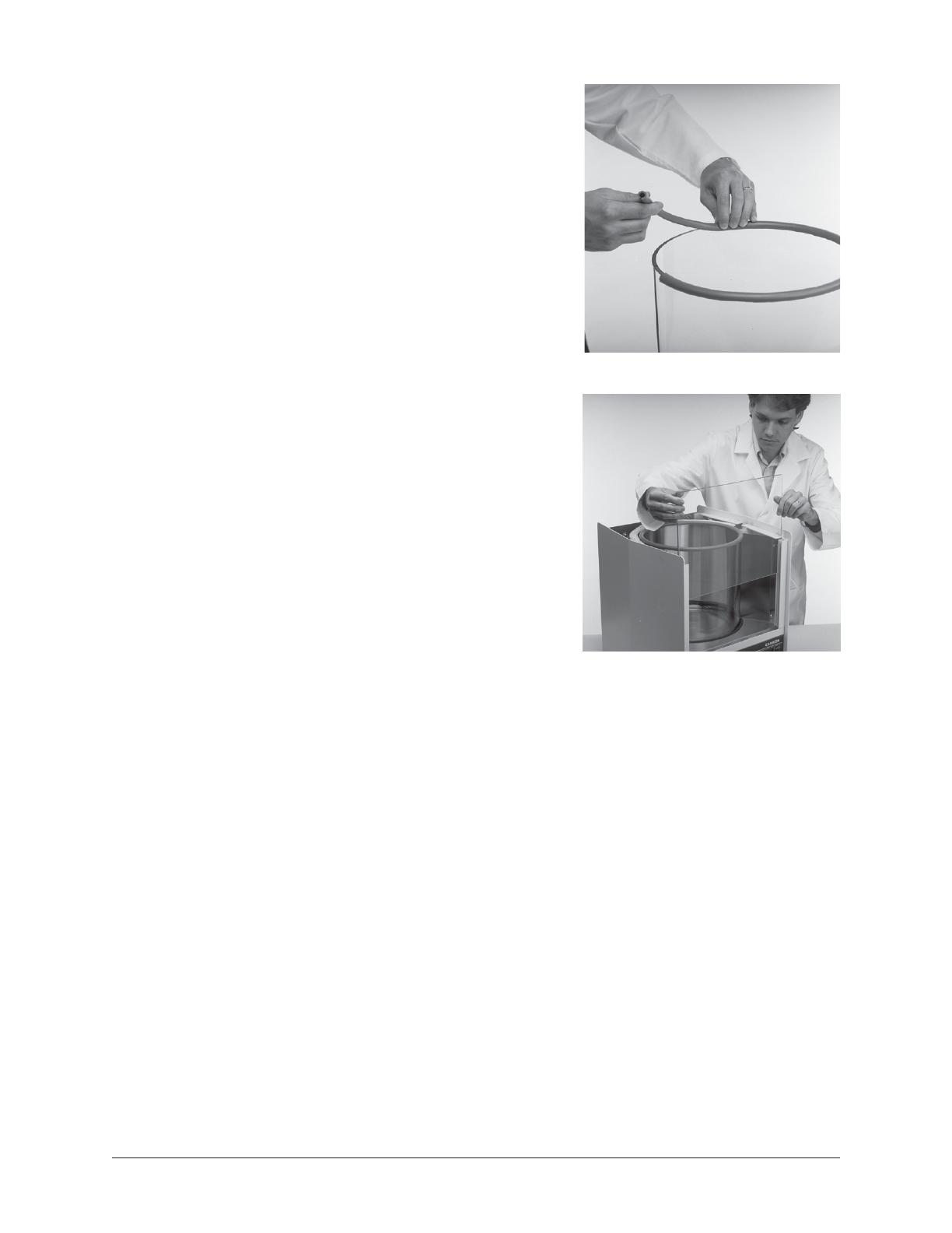
rubber may have to be
trimmed slightly to allow the
ends of the rubber gasket to
meet with no gap when
placed around the rim.
4. Remove the large piece of
foam packing from the inside
of the cabinet. Also remove
the small piece of foam from
the float level, located on the
upper left-hand corner of the
inside of the cabinet.
5. Lower the glass jar into the
cabinet so it seats evenly on
the rubber support ring.
6. Unwrap the two glass
panels. Place the thinner of
the two pieces of glass in the
slot closest to the jar (see
Figure 7).
7. Place the wider (tempered)
piece of glass in the front
slot furthest away from the
jar. The middle slot is left
empty as a vapor barrier.
8. Replace the rear top cover.
Align the four holes, then
insert and tighten the screws.
9. Replace the front top cover. Line up the four holes, then insert and
tighten the screws.
10. To ensure that the gasket forms a tight seal with the top covers of the
bath, proceed as follows:
11. Loosen the IEC lock screw securing the AC power cord to the rear
panel of the electronics drawer. Then unplug all three cables (AC
power, rectangular Cinch connector and round Amp connector) from
the rear of the electronics drawer.
12. Pull out the electronics drawer using the handles provided on the
front of the unit. Press down or pull up on the plastic release bars on
either side of the drawer track to release the drawer, then pull the
drawer completely free of the unit and set it aside.
13. When the drawer is removed, locate the four ¼-20 set screws visible
at the top of the drawer opening underneath the bath.
Figure 6: Seating the gasket
Figure 7: Placing inner glass panel
8
CANNON
®
CT-2000 Constant Temperature Bath
Revision 1.0g—February, 2012; CANNON
®
Instrument Company
2139 High Tech Road • State College, PA 16803 • USA
14. Turn the set screws clockwise with the Allen wrench (included with
the bath) until the top of the jar forms a tight seal with the covers.
Make sure you tighten the set screws uniformly so the jar remains
level.
15. Run the AC cord through the rear panel opening.
16. Replace the drawer in the slide tracks and push the drawer back into
its opening. Insert the two power plugs into the rear of the drawer
assembly.
Motor-stirrer
Complete the assembly of the bath by inserting the motor-stirrer per the
instructions below:
1. Take the motor/stirrer from
its box. Remove the two
screws on the top heater
housing and lift off the
housing (see Figure 8).
2. Check the motor-stirrer
impeller blades to make
sure that the flat sections
all lie in the same plane
(see APPENDIX B), then
insert the motor stirrer into
the opening provided (see
Figure 9).
NOTE
To avoid accidental bending of
the motor shaft, do not hold the
motor assembly by the shaft.
Use care when inserting the
motor shaft and impeller to
prevent damage to delicate
components. Two screws
located on either side of the
opening for the motor stirrer
serve as locating pins for the
motor support pad. Do not
remove these screws; the
holes in the pad fit loosely over
their heads. The motor line
cord should point toward the
rear of the bath (offset slightly
to the right or left). The motor
stirrer should now lie flat on the
top of the bath.
3. Connect all plugs and probes to the correspondingly labeled sockets
at the rear of the CT-2000 bath unit as follows (see Figure 10):
Figure 8: Removing heater housing
Figure 9: Installing motor-stirrer
9
CANNON
®
CT-2000 Constant Temperature Bath
Revision 1.0g—February, 2012; CANNON
®
Instrument Company
2139 High Tech Road • State College, PA 16803 • USA
PREHEAT cable to PREHEAT socket
CONTROL HEATER cable to CONTROL HEATER socket
FAN cable to FAN socket
MOTOR STIRRER cable to MOTOR socket
CONTROL PROBE cable to CONTROL PROBE socket
OVER TEMP cable to OVER TEMP socket
LEVEL FLOAT CABLE to LEVEL FLOAT socket
4. Reattach the top heater housing, making sure that the heater, motor,
and fan cords pass through the left-hand opening (as viewed from the
rear) and that the control probe, over-temperature probe, and level
switch cords exit from the right opening (as viewed from the rear).
The back lip on the rear top cover fits into the slot on the top heater
housing. Line up the holes, insert screws, and tighten.
5. Adjust the four feet on the bottom of the bath housing to level the
bath jar. This should be done prior to filling the bath with fluid.
6. Plug the CT-2000 main power cord at the back of the electronics
drawer into an outlet with electrical specifications matching the label
on the rear of the instrument.
Inserting viscometer tubes/thermometers
The top cover of the CT-2000 contains seven apertures, 51 mm (2") in
diameter, for the insertion of viscometer tube holders. Two additional
holes are provided for insertion of thermometers.
Inserting viscometer tubes
Remove the viscometer tube cover(s) from the top of the bath and
carefully place the viscometer tube(s), with the proper holder attached,
into the bath through the aperture(s) in the top cover. The viscometer tube
should be inserted to a depth which ensures that the liquid under test and/
or any timing marks are a minimum of 6 mm (¼") below the top level of
the liquid.
Figure 10: CT-2000
electrical connections
10
CANNON
®
CT-2000 Constant Temperature Bath
Revision 1.0g—February, 2012; CANNON
®
Instrument Company
2139 High Tech Road • State College, PA 16803 • USA
Thermometer immersion
Proper thermometer immersion is critical for viscosity measurements.
Even a calibrated thermometer will read incorrectly if is it improperly
immersed in the bath. “Total immersion” kinematic viscosity thermom-
eters should be used with the bulb and only the mercury column beneath
the surface of the liquid, but with the emergent stem above the surface at
ambient temperatures.
Filling the bath
CAUTION
Make sure that the bath is placed in
its intended final position before
adding bath fluid. The CT-2000
should not be moved with bath fluid
in the bath jar. NEVER USE FLAM-
MABLE BATH LIQUIDS.
1. Make sure that the instrument
power is OFF and select a bath
liquid appropriate to your operat-
ing temperature range (see
APPENDIX C).
2. Fill the jar with bath liquid at ambient temperature to a level suffi-
cient to engage the float switch. This float permits bath operation
when the minimum amount of fluid has been added to the bath jar.
3. Continue to add fluid until the bath liquid level has risen to approxi-
mately 40 mm (1.5") of the top of the jar.
4. Turn the instrument power ON and incrementally heat the bath to
desired control temperature while monitoring the bath liquid level
carefully. The bath level must be 15-20 mm (approximately ½" to
¾") from the top of the jar at the control temperature. If it becomes
apparent that this liquid level will not be achieved, return the bath to
within 10°C of ambient, turn the instrument power OFF and add or
remove liquid as necessary.
5. Repeat step four until you have attained the proper bath liquid level
at the desired control temperature.
CAUTION
Different bath fluids expand at different rates. Do not overfill the bath!
WARNING Monitor the level of bath liquid closely when operating the CT-2000 at
higher temperatures (100-150°C). The bath liquid will expand as the
temperature increases. The CT-2000 bath jar is not designed to contain
liquid under pressure. If the bath is overfilled, liquid may overflow.
Figure 11: Filling the bath
11
CANNON
®
CT-2000 Constant Temperature Bath
Revision 1.0g—February, 2012; CANNON
®
Instrument Company
2139 High Tech Road • State College, PA 16803 • USA
Draining the Bath
If it becomes necessary to drain the liquid from the bath:
Obtain a suitable container to hold all of the liquid drained from the bath
(approximately 20-22 liters or 4.5 - 5 gallons). Make sure that the bath
liquid is within 10°C of ambient temperature. Then insert a tube into the
bath chamber from the top opening and siphon the liquid from the bath
into a container positioned lower than the bath.
WARNING
Always use a rubber bulb or similar device to apply suction to a tube
containing bath liquids.
CANNON
®
CT-2000 Constant Temperature Bath
Revision 1.0g—February, 2012; CANNON
®
Instrument Company
2139 High Tech Road • State College, PA 16803 • USA
12
This page intentionally left blank.
CANNON
®
CT-2000 Constant Temperature Bath
Revision 1.0g—February, 2012; CANNON
®
Instrument Company
2139 High Tech Road • State College, PA 16803 • USA
13
CHAPTER
BATH OPERATION
NOTE
Different thermometers have different installation requirements. Refer to
the information included with the thermometer in use for specific installa-
tion instructions.
Applying power
Caution
Do not power up the CT-2000 without completing the installation require-
ments. Make sure that the mains voltage specified on the rear identifica-
tion label matches your mains voltage.
NOTE
The CT-2000 stores the “last-used” temperature setting in memory, so
that on power-up the bath will attempt to adjust to the last known and
entered temperature.
Cold Start
The Cold Start is the normal start-up mode for the CT-2000. During the
Cold Start process, the CT-2000 will perform several diagnostics (see
Self-Test Sequence, next page). At the conclusion of a successful test
procedure, the results will be briefly displayed on the LCD screen. The
bath heaters will be activated and the Bath Unit will begin controlling
temperature according to the most recent temperature input. The current
bath temperature and the target bath temperature will be visible on the
liquid crystal display (LCD):
3
14
CANNON
®
CT-2000 Constant Temperature Bath
Revision 1.0g—February, 2012; CANNON
®
Instrument Company
2139 High Tech Road • State College, PA 16803 • USA
TEMPERATURE
Actual Target
20.003 C 100.000 C
HEATING
To Cold Start the CT-2000, toggle the power BATH switch up. The
POWER lamp should light when bath power has been activated. The
five LEDs in the lower row of keys will blink on and then off, and the
instrument will emit a short “beep” tone.
Bath lighting
To activate Bath Unit fluorescent lights, toggle the LIGHTS switch up.
The switch lamp indicator will light when power is supplied to the
fluorescent lights.
Warm Start
The Warm Start is the abnormal start-up mode for the bath and it occurs
only if the power was previously off for a period less than about two
seconds, or if a fault was detected in the microprocessor during the self-
test sequence (see below). If the CT-2000 Process Function Monitor
senses a momentary or ongoing failure in the system hardware or
software, the heating elements will be shut down and the system will be
reactivated in Warm Start mode. The keypad lights will flash in a repeat-
ing pattern and the heater power will be disabled (heating LED will not
light).
The display will show the following:
POWER UP
Warm Start
Consult User’s Guide
If this condition is ever discovered, the BATH power switch should be
turned off. After waiting at least five seconds, turn the BATH power
switch to the ON position and wait for the display to indicate either a
warm or cold start again. If the bath comes up in a cold start condition
and starts its normal self-test sequence, it is possible that a momentary
power interruption caused the warm start condition and no further action
is required. If the bath continues to enter the warm start condition, the
user should consult CANNON
®
Instrument Company for further assis-
tance.
Self-test sequence
The CT-2000 start-up includes a self-test procedure encompassing key
components of the system. These tests, which will be displayed on the
LCD during start-up, are described in the following table:
15
CANNON
®
CT-2000 Constant Temperature Bath
Revision 1.0g—February, 2012; CANNON
®
Instrument Company
2139 High Tech Road • State College, PA 16803 • USA
tseT-fleS0002-TC
:TSET :ESOPRUPTSET
yalpsiD
ehT.neercs)DCL(yalpsidlatsyrcdiuqilehtfonoitcnufseifireV
.yalpsidehtnostnemgesdabro
fkcehcyllausivyamresu
MARK23 .yromemmetsys0002-TCfonoitarepolamronseifireV
esluP
htdiW
rotaludoM
.MWPehtfon
oitcnufseifireV
D/A
dnanoitcnufseifirevdnaretrevnoclatigidgolanasetarbilaC
.ycnetsisnoc
egatloV
sleveL
.)e
vitagendnaevitisop(slevelegatlovylppusrewopseifireV
The following sequence illustrates the LCD for a normal self-test:
Testing Display



Testing 32k RAM ...

 Test Passed 
Testing Pulse Width
Modulator.....

 Test Passed 
Testing A/D .....
Calibrating ....OK
Consistency ....OK
Testing Voltage Levels
......
Positive Supply..OK
Negative Supply..OK
Diagnostic Report
All tests PASSED
Entering Normal
Operation
16
CANNON
®
CT-2000 Constant Temperature Bath
Revision 1.0g—February, 2012; CANNON
®
Instrument Company
2139 High Tech Road • State College, PA 16803 • USA
If the self-test sequence is accomplished successfully, the CT-2000 will
commence normal operations.
If any component of the self-test fails, the following message will appear
on the LCD, accompanied by an audible warning tone:
Diagnostics Report
Some Tests FAILED
See Owner's Manual
Press ENTER to go on
The ENTER key will flash in a repeating pattern and the heating LED
will not light (see Warm Start information, page 12). In the event of a
FAILED test, turn off the CT-2000 power for at least five seconds and
restart the unit.
It may be possible to resume normal operation of the CT-2000 following
a failed self-test by pressing the ENTER key. If you do so, the following
LCD message will appear:
Attempting Normal
Operation
Proceed with CAUTION
CAUTION
A failed self-test may result in flawed operation and damage to the CT-
2000. If the CT-2000 repeatedly fails the self-test sequence, call
CANNON
®
to arrange for servicing the unit.
Following the self-test, the CT-2000 will enter its normal display condi-
tion provided that the RTD temperature sensor is connected properly. If
the RTD sensor is unplugged at any time, the LCD will display a warning
and it will be necessary to reconnect the RTD before proceeding with
normal CT-2000 operations.
The RTD sensor has
been disconnected.
Please reconnect it
to reset the Bath.
Front panel operations
Following a successful Cold Start, the CT-2000 is ready for instructions
from the user.
NOTE
Please check bath fluid levels before using the CT-2000 menu com-
mands (see page 10).
17
CANNON
®
CT-2000 Constant Temperature Bath
Revision 1.0g—February, 2012; CANNON
®
Instrument Company
2139 High Tech Road • State College, PA 16803 • USA
The front panel of the CT-2000 provides a Liquid Crystal Display (LCD)
screen and a simple keypad interface (see Figure 12).
12).
Figure 12: The CT-2000 front panel
Using the keypad
The keypad on the front panel of the CT-2000 consists of fifteen keys:
white numbers 0 through 9
a white decimal point (.) key
a yellow SET TEMP (set temperature) key
a yellow CAL TEMP (calibrate temperature) key
a yellow MENU key an orange ENTER key
The keys on the bottom row (non-numerical keys) may illuminate to
assist the operator in selecting key entry options.
Press the appropriate keypad choice(s) firmly to make your selections.
The CT-2000 will signal reception of each keypad command with a short,
high-pitched “beep”. A longer beep indicates a data entry error (unaccept-
able input), such as a temperature value outside the range of the unit.
The
ENTER
button
The ENTER button is the most-used feature on the CT-2000 keypad. You
must confirm each menu choice and numeric input by pressing this
button.
Selecting/canceling options
To access any of the primary keypad options (SET TEMP, CAL TEMP
and MENU), press the appropriate keypad button once. If you make a
data entry error and wish to cancel your input sequence, press the pri-
mary keypad option button again.
NOTE
If the keypad does not receive user input for five minutes after a primary
option is selected, the instrument will return to the LCD temperature
display screen without saving any changes.
Initial options
Only three keypad options are enabled when the Cold Start routine is
begun—SET TEMP, CAL TEMP and MENU:
SET TEMP allows user to type in the desired bath temperature
setting. See details below.
CAL TEMP allows user to recalibrate the temperature sensing
mechanism. See Calibrating the CT-2000, page 17).
18
CANNON
®
CT-2000 Constant Temperature Bath
Revision 1.0g—February, 2012; CANNON
®
Instrument Company
2139 High Tech Road • State College, PA 16803 • USA
MENU allows user to change temperature scale (°F-°C), reset
calibration offsets and change other system settings (See Menu
options).
Setting bath temperature
SET TEMP
To set the bath temperature, choose SET TEMP from the keypad after a
successful Cold Start. The LCD will display a message requesting user
input of the new target temperature. Use the numeral keys to input the
new temperature. You may enter positive numbers from 10°C to 150°C
(50°F. To 302°F.) to three decimal places. Press the ENTER key to save
your data. The bath will attempt to control at the new temperature.
You may reset the temperature at any time.
Correcting data entry errors
If you make an error while setting the temperature, press the SET TEMP
key again to exit the data entry screen. Then repeat the SET TEMP
procedure.
Lower temperatures
When the desired temperature setting is slightly above, or below ambient,
coolant must be circulated through the cooling coil. Input/output connec-
tions for the coil are located on the upper portion of the rear panel.
Coolant temperature should be lower than the desired CT-2000 control
temperature.
NOTE
Extreme temperatures or variability in the temperature of the coolant
liquid may adversely affect CT-2000 temperature control.
NOTE If a temperature is entered which is outside of the operational tempera-
ture range of the CT-2000, you will receive a RANGE ERROR message
on the LCD screen. To correct this error, press ENTER and follow the
screen prompts to enter appropriate data.
When the CT-2000 is controlling temperature within one tenth of a
degree, the LCD will display a temperature graph in 5/100ths of a degree
increments at the bottom of the LCD screen. A small “tick” mark above
the graph will provide a visual cue to the exact temperature of the bath
relative to the requested temperature.
TEMPERATURE
Actual Target
40.003 C 40.000 C
-.1 |....|....|....|....|+.1
I
  • Page 1 1
  • Page 2 2
  • Page 3 3
  • Page 4 4
  • Page 5 5
  • Page 6 6
  • Page 7 7
  • Page 8 8
  • Page 9 9
  • Page 10 10
  • Page 11 11
  • Page 12 12
  • Page 13 13
  • Page 14 14
  • Page 15 15
  • Page 16 16
  • Page 17 17
  • Page 18 18
  • Page 19 19
  • Page 20 20
  • Page 21 21
  • Page 22 22
  • Page 23 23
  • Page 24 24
  • Page 25 25
  • Page 26 26
  • Page 27 27
  • Page 28 28
  • Page 29 29
  • Page 30 30
  • Page 31 31
  • Page 32 32
  • Page 33 33
  • Page 34 34
  • Page 35 35
  • Page 36 36
  • Page 37 37
  • Page 38 38
  • Page 39 39
  • Page 40 40

Cannon CT-2000 User manual

Category
Camcorders
Type
User manual
This manual is also suitable for

Ask a question and I''ll find the answer in the document

Finding information in a document is now easier with AI