Western Telematic MPC-20V-1 MPC-8H-2 User manual
- Category
- Networking
- Type
- User manual

WTI Part No. 13762
Rev. G
MPC Series
Managed Power Controllers
Models Covered:
MPC-8H-1 MPC-20VS20-1 MPC-20VS20-2 MPC-20VS16-3 MPC-20V-1
MPC-8H-2 MPC-20VD20-1 MPC-20VD20-2 MPC-20VD16-3 MPC-20V-2
MPC-16H-1 MPC-20VS30-1 MPC-20VS30-2 MPC-20VS32-3 MPC-DISPLAY
MPC-16H-2 MPC-20VD30-1 MPC-20VD30-2 MPC-20VD32-3
MPC-18H-1
MPC-18H-2
Firmware Version 1.50 and Higher
User's Guide

i
Warnings and Cautions:
Installation Instructions
Secure Racking
If Secure Racked units are installed in a closed or multi-unit rack assembly, they may
require further evaluation by Certification Agencies. The following items must be
considered.
1. The ambient within the rack may be greater than room ambient. Installation
should be such that the amount of air flow required for safe operation is not
compromised. The maximum temperature for the equipment in this environment is
55°C. Consideration should be given to the maximum rated ambient.
2. Installation should be such that a hazardous stability condition is not achieved due
to uneven loading.
3. Side vents are used to dissipate heat generated within the unit. When mounting
the unit in an equipment rack, make certain to allow adequate clearance for
venting.
Input Supply
Check nameplate ratings to assure there is no overloading of supply circuits that could
have an effect on overcurrent protection and supply wiring.
Grounding
Reliable earthing of this equipment must be maintained. Particular attention should
be given to supply connections when connecting to power strips, rather than direct
connections to the branch circuit.
No Serviceable Parts Inside; Authorized Service Personnel Only
Do not attempt to repair or service this device yourself. Internal components must be
serviced by authorized personnel only.
• Shock Hazard - Do Not Enter
• Lithium Battery
CAUTION: Danger of explosion if battery is incorrectly replaced. Replace
only with same or equivalent type recommended by the manufacturer.
Discard used batteries according to the manufacturer's instructions.

ii
Warnings and Cautions
Disconnect Power
If any of the following events are noted, immediately disconnect the unit from the outlet
and contact qualified service personnel:
1. If the power cord becomes frayed or damaged.
2. If liquid has been spilled into the device or if the device has been exposed to rain
or water.
Two Power Supply Cables
Note that some MPC series units feature two separate power circuits, and a separate
power supply cable for each power circuit. If your MPC unit includes two power supply
cables, make certain to disconnect both power supply cables from their power source
before attempting to service or remove the unit.
Detached 15-Amp “Starter” Cable(s)
If the MPC unit includes a detached, 125 VAC, 15 Amp “Starter” Cable(s,) this allows
you to connect the MPC to power for bench testing and initial start up is adequate for
applications that only require 15 Amps. For 20-Amp power switching applications,
please refer to the WTI Power Cable guide supplied with the unit, or use appropriate 20-
Amp cables.
Units with Attached Power Supply Cable(s)
For MPC units that include attached power supply cable(s), the socket outlet(s) shall be
installed near the equipment and shall be accessible.

iii
Agency Approvals
FCC Part 15 Regulation
This equipment has been tested and found to comply with the limits for a Class A digital
device, pursuant to part 15 of the FCC Rules. These limits are designed to provide
reasonable protection against harmful interference when the equipment is operated
in a commercial environment. This equipment generates, uses, and can radiate radio
frequency energy and, if not installed and used in accordance with the instruction
manual, may cause harmful interference to radio communications. Operation of this
equipment in a residential area is likely to cause harmful interference in which case the
user will be required to correct the interference at his own expense.
This device complies with part 15 of the FCC Rules. Operation is subject to the following
two conditions: (1) This device may not cause harmful interference, and (2) this device
must accept any interference received, including interference that may cause undesired
operation
WARNING: Changes or modifications to this unit not expressly approved by
the party responsible for compliance could void the user’s authority to operate
the equipment
EMC, Safety, and R&TTE Directive Compliance
The CE mark is affixed to this product to confirm compliance with the following
European Community Directives:
• Council Directive 89/336/EEC of 3 May 1989 on the approximation of the laws
of Member States relating to electromagnetic compatibility;
and
• Council Directive 73/23/EEC of 19 February 1973 on the harmonization of
the laws of Member States relating to electrical equipment designed for use
within certain voltage limits;
and
• Council Directive 1999/5/EC of 9 March on radio equipment and
telecommunications terminal equipment and the mutual recognition of their
conformity.
Industry Canada - EMI Information
This Class A digital apparatus complies with Canadian ICES-003.
Cet appareil numérique de la classe A est conforme à la norme NMB-003 du Canada.

iv
Table of Contents
1. Introduction . . . . . . . . . . . . . . . . . . . . . . . . . . . . . . . . . . . . . . . . . . . . . . . . . . . . . . . . . . . . . 1-1
2. Unit Description . . . . . . . . . . . . . . . . . . . . . . . . . . . . . . . . . . . . . . . . . . . . . . . . . . . . . . . . . .
2-1
2.1. MPC-H Series - Front Panel . . . . . . . . . . . . . . . . . . . . . . . . . . . . . . . . . . . . . . . . . . . . . . 2-1
2.2. MPC-H Series - Back Panel . . . . . . . . . . . . . . . . . . . . . . . . . . . . . . . . . . . . . . . . . . . . . . 2-3
2.3. MPC-V Series - Hardware Description . . . . . . . . . . . . . . . . . . . . . . . . . . . . . . . . . . . . . . 2-4
2.4. Additional Button Functions . . . . . . . . . . . . . . . . . . . . . . . . . . . . . . . . . . . . . . . . . . . . . . 2-7
3. Getting Started . . . . . . . . . . . . . . . . . . . . . . . . . . . . . . . . . . . . . . . . . . . . . . . . . . . . . . . . . . 3-1
3.1. Installing the MPC Hardware . . . . . . . . . . . . . . . . . . . . . . . . . . . . . . . . . . . . . . . . . . . . . 3-1
3.1.1. Apply Power to the MPC
. . . . . . . . . . . . . . . . . . . . . . . . . . . . . . . . . . . . . . . . . . 3-1
3.1.2. Connect your PC to the MPC . . . . . . . . . . . . . . . . . . . . . . . . . . . . . . . . . . . . . . .
3-3
3.2. Communicating with the MPC . . . . . . . . . . . . . . . . . . . . . . . . . . . . . . . . . . . . . . . . . . . . 3-3
3.3. Installing and Operating the Optional MPC-DISPLAY Hardware . . . . . . . . . . . . . . . . . . 3-5
4. Hardware Installation . . . . . . . . . . . . . . . . . . . . . . . . . . . . . . . . . . . . . . . . . . . . . . . . . . . . . 4-1
4.1. Connecting the Power Supply Cables . . . . . . . . . . . . . . . . . . . . . . . . . . . . . . . . . . . . . . 4-1
4.1.1. Installing the Power Supply Cable Keepers . . . . . . . . . . . . . . . . . . . . . . . . . . . .
4-1
4.1.2. Connect the MPC to Your Power Supply . . . . . . . . . . . . . . . . . . . . . . . . . . . . . .
4-3
4.2. Connection to Switched Outlets . . . . . . . . . . . . . . . . . . . . . . . . . . . . . . . . . . . . . . . . . . 4-3
4.3. Serial Console Port Connection . . . . . . . . . . . . . . . . . . . . . . . . . . . . . . . . . . . . . . . . . . . 4-4
4.3.1. Connecting a Local PC
. . . . . . . . . . . . . . . . . . . . . . . . . . . . . . . . . . . . . . . . . . . 4-4
4.3.2. Connecting an External Modem
. . . . . . . . . . . . . . . . . . . . . . . . . . . . . . . . . . . . 4-4
4.4. Connecting the Network Cable . . . . . . . . . . . . . . . . . . . . . . . . . . . . . . . . . . . . . . . . . . . 4-4
4.5. Connecting Remote MPC Units to the AUX Ports . . . . . . . . . . . . . . . . . . . . . . . . . . . . . 4-5
4.6. Connecting the Optional MPC-DISPLAY Unit . . . . . . . . . . . . . . . . . . . . . . . . . . . . . . . . 4-6
4.7. Rack Mounting . . . . . . . . . . . . . . . . . . . . . . . . . . . . . . . . . . . . . . . . . . . . . . . . . . . . . . . . 4-6
5. Basic Configuration . . . . . . . . . . . . . . . . . . . . . . . . . . . . . . . . . . . . . . . . . . . . . . . . . . . . . . 5-1
5.1. Communicating with the MPC Unit . . . . . . . . . . . . . . . . . . . . . . . . . . . . . . . . . . . . . . . . 5-1
5.1.1. The Text Interface . . . . . . . . . . . . . . . . . . . . . . . . . . . . . . . . . . . . . . . . . . . . . . . .
5-1
5.1.2. The Web Browser Interface
. . . . . . . . . . . . . . . . . . . . . . . . . . . . . . . . . . . . . . . . 5-3
5.1.3. Access Via PDA
. . . . . . . . . . . . . . . . . . . . . . . . . . . . . . . . . . . . . . . . . . . . . . . . . 5-4
5.2. Configuration Menus . . . . . . . . . . . . . . . . . . . . . . . . . . . . . . . . . . . . . . . . . . . . . . . . . . . 5-5
5.3. Defining System Parameters . . . . . . . . . . . . . . . . . . . . . . . . . . . . . . . . . . . . . . . . . . . . . 5-7
5.3.1. The Real Time Clock and Calendar . . . . . . . . . . . . . . . . . . . . . . . . . . . . . . . . . .
5-9
5.3.2. The Invalid Access Lockout Feature
. . . . . . . . . . . . . . . . . . . . . . . . . . . . . . . . 5-11
5.3.3. Automated Mode
. . . . . . . . . . . . . . . . . . . . . . . . . . . . . . . . . . . . . . . . . . . . . . . 5-13
5.3.4. Log Configuration . . . . . . . . . . . . . . . . . . . . . . . . . . . . . . . . . . . . . . . . . . . . . . .
5-14
5.3.4.1. The Audit Log and Alarm Log
. . . . . . . . . . . . . . . . . . . . . . . . . . . . . 5-15
5.3.4.2. The Current Metering Log and Power Metering Log . . . . . . . . . . . .
5-15
5.3.4.3. Reading and Erasing Logs
. . . . . . . . . . . . . . . . . . . . . . . . . . . . . . . 5-16
5.3.5. Callback Security . . . . . . . . . . . . . . . . . . . . . . . . . . . . . . . . . . . . . . . . . . . . . . .
5-17
5.4. User Accounts . . . . . . . . . . . . . . . . . . . . . . . . . . . . . . . . . . . . . . . . . . . . . . . . . . . . . . . 5-19
5.4.1. Command Access Levels
. . . . . . . . . . . . . . . . . . . . . . . . . . . . . . . . . . . . . . . . 5-19
5.4.2. Plug Access
. . . . . . . . . . . . . . . . . . . . . . . . . . . . . . . . . . . . . . . . . . . . . . . . . . . 5-20
5.4.3. Port Access
. . . . . . . . . . . . . . . . . . . . . . . . . . . . . . . . . . . . . . . . . . . . . . . . . . . 5-21
5.5. Managing User Accounts . . . . . . . . . . . . . . . . . . . . . . . . . . . . . . . . . . . . . . . . . . . . . . . 5-22
5.5.1. Viewing User Accounts
. . . . . . . . . . . . . . . . . . . . . . . . . . . . . . . . . . . . . . . . . . 5-22
5.5.2. Adding User Accounts . . . . . . . . . . . . . . . . . . . . . . . . . . . . . . . . . . . . . . . . . . .
5-24
5.5.2.1. Granting User Account Access to Plugs on AUX Units . . . . . . . . . .
5-27
5.5.3. Modifying User Accounts . . . . . . . . . . . . . . . . . . . . . . . . . . . . . . . . . . . . . . . . .
5-28
5.5.4. Deleting User Accounts . . . . . . . . . . . . . . . . . . . . . . . . . . . . . . . . . . . . . . . . . .
5-28

Table of Contents
v
5. Basic Configuration (continued)
5.6. The Plug Group Directory . . . . . . . . . . . . . . . . . . . . . . . . . . . . . . . . . . . . . . . . . . . . . . 5-29
5.6.1. Viewing Plug Groups
. . . . . . . . . . . . . . . . . . . . . . . . . . . . . . . . . . . . . . . . . . . . 5-30
5.6.2. Adding Plug Groups . . . . . . . . . . . . . . . . . . . . . . . . . . . . . . . . . . . . . . . . . . . . .
5-32
5.6.2.1. Granting User Account Access to Plugs on AUX Units . . . . . . . . . .
5-33
5.6.3. Modifying Plug Groups
. . . . . . . . . . . . . . . . . . . . . . . . . . . . . . . . . . . . . . . . . . 5-34
5.6.4. Deleting Plug Groups . . . . . . . . . . . . . . . . . . . . . . . . . . . . . . . . . . . . . . . . . . . .
5-34
5.7. Defining Plug Parameters . . . . . . . . . . . . . . . . . . . . . . . . . . . . . . . . . . . . . . . . . . . . . . . 5-36
5.7.1. The Boot Priority Parameter . . . . . . . . . . . . . . . . . . . . . . . . . . . . . . . . . . . . . . .
5-38
5.7.1.1. Example 1: Change Plug A3 to Priority 1 . . . . . . . . . . . . . . . . . . . .
5-38
5.7.1.2. Example 2: Change Plug A5 to Priority 2 . . . . . . . . . . . . . . . . . . . .
5-39
5.8. Serial Port Configuration . . . . . . . . . . . . . . . . . . . . . . . . . . . . . . . . . . . . . . . . . . . . . . . 5-41
5.8.1. Console Port Configuration
. . . . . . . . . . . . . . . . . . . . . . . . . . . . . . . . . . . . . . . 5-41
5.8.2. Remote Port and AUX Port Configuration
. . . . . . . . . . . . . . . . . . . . . . . . . . . . 5-45
5.9. Network Configuration . . . . . . . . . . . . . . . . . . . . . . . . . . . . . . . . . . . . . . . . . . . . . . . . . 5-48
5.9.1. Network Port Parameters . . . . . . . . . . . . . . . . . . . . . . . . . . . . . . . . . . . . . . . . . 5-49
5.9.2. Network Parameters . . . . . . . . . . . . . . . . . . . . . . . . . . . . . . . . . . . . . . . . . . . . . 5-50
5.9.3. IP Security
. . . . . . . . . . . . . . . . . . . . . . . . . . . . . . . . . . . . . . . . . . . . . . . . . . . . 5-51
5.9.3.1. Adding IP Addresses to the Allow and Deny Lists
. . . . . . . . . . . . . 5-52
5.9.3.2. Linux Operators and Wild Cards . . . . . . . . . . . . . . . . . . . . . . . . . . .
5-53
5.9.3.3. IP Security Examples . . . . . . . . . . . . . . . . . . . . . . . . . . . . . . . . . . . .
5-53
5.9.4. Static Route . . . . . . . . . . . . . . . . . . . . . . . . . . . . . . . . . . . . . . . . . . . . . . . . . . . 5-54
5.9.5. Domain Name Server . . . . . . . . . . . . . . . . . . . . . . . . . . . . . . . . . . . . . . . . . . . .
5-54
5.9.6. SNMP Access Parameters . . . . . . . . . . . . . . . . . . . . . . . . . . . . . . . . . . . . . . . .
5-55
5.9.7. SNMP Trap Parameters
. . . . . . . . . . . . . . . . . . . . . . . . . . . . . . . . . . . . . . . . . . 5-57
5.9.8. LDAP Parameters . . . . . . . . . . . . . . . . . . . . . . . . . . . . . . . . . . . . . . . . . . . . . . .
5-58
5.9.8.1. Adding LDAP Groups . . . . . . . . . . . . . . . . . . . . . . . . . . . . . . . . . . . .
5-60
5.9.8.2 Viewing LDAP Groups
. . . . . . . . . . . . . . . . . . . . . . . . . . . . . . . . . . . 5-61
5.9.8.3. Modifying LDAP Groups
. . . . . . . . . . . . . . . . . . . . . . . . . . . . . . . . . 5-62
5.9.8.4. Deleting LDAP Groups . . . . . . . . . . . . . . . . . . . . . . . . . . . . . . . . . . .
5-62
5.9.8.5. LDAP Kerberos Set Up . . . . . . . . . . . . . . . . . . . . . . . . . . . . . . . . . . .
5-63
5.9.9. TACACS Parameters
. . . . . . . . . . . . . . . . . . . . . . . . . . . . . . . . . . . . . . . . . . . . 5-64
5.9.10. RADIUS Parameters . . . . . . . . . . . . . . . . . . . . . . . . . . . . . . . . . . . . . . . . . . . . .
5-65
5.9.10.1. Dictionary Support for RADIUS
. . . . . . . . . . . . . . . . . . . . . . . . . . . . 5-66
5.9.11. Email Message Parameters . . . . . . . . . . . . . . . . . . . . . . . . . . . . . . . . . . . . . . .
5-68
5.10. Save User Selected Parameters . . . . . . . . . . . . . . . . . . . . . . . . . . . . . . . . . . . . . . . . . 5-69
5.10.1. Restore Configuration
. . . . . . . . . . . . . . . . . . . . . . . . . . . . . . . . . . . . . . . . . . . 5-69
6. Reboot Options . . . . . . . . . . . . . . . . . . . . . . . . . . . . . . . . . . . . . . . . . . . . . . . . . . . . . . . . . . 6-1
6.1. Ping-No-Answer Reboot . . . . . . . . . . . . . . . . . . . . . . . . . . . . . . . . . . . . . . . . . . . . . . . . . 6-2
6.1.1. Adding Ping-No-Answer Reboots
. . . . . . . . . . . . . . . . . . . . . . . . . . . . . . . . . . . 6-2
6.1.1.1. Granting Access to Plugs on AUX Units . . . . . . . . . . . . . . . . . . . . . . 6-4
6.1.2. Viewing Ping-No-Answer Reboot Profiles
. . . . . . . . . . . . . . . . . . . . . . . . . . . . . 6-4
6.1.3. Modifying Ping-No-Answer Reboot Profiles . . . . . . . . . . . . . . . . . . . . . . . . . . . 6-5
6.1.4. Deleting Ping-No-Answer Reboot Profiles . . . . . . . . . . . . . . . . . . . . . . . . . . . . . 6-5
6.2. Scheduled Reboot . . . . . . . . . . . . . . . . . . . . . . . . . . . . . . . . . . . . . . . . . . . . . . . . . . . . . 6-6
6.2.1. Adding Scheduled Reboots . . . . . . . . . . . . . . . . . . . . . . . . . . . . . . . . . . . . . . . .
6-6
6.2.1.1. Granting Access to Plugs on AUX Units . . . . . . . . . . . . . . . . . . . . . . 6-8
6.2.2. Viewing Scheduled Reboot Actions . . . . . . . . . . . . . . . . . . . . . . . . . . . . . . . . . .
6-8
6.2.3. Modifying Scheduled Reboots . . . . . . . . . . . . . . . . . . . . . . . . . . . . . . . . . . . . . . 6-9
6.2.4. Deleting Scheduled Reboots . . . . . . . . . . . . . . . . . . . . . . . . . . . . . . . . . . . . . . . 6-9

Table of Contents
vi
7. Alarm Configuration . . . . . . . . . . . . . . . . . . . . . . . . . . . . . . . . . . . . . . . . . . . . . . . . . . . . . . 7-1
7.1. The Over Current Alarms . . . . . . . . . . . . . . . . . . . . . . . . . . . . . . . . . . . . . . . . . . . . . . . . 7-2
7.1.1. Over Current Alarms - Load Shedding and Auto Recovery
. . . . . . . . . . . . . . . 7-4
7.1.1.1. Granting Access to Plugs on AUX Units . . . . . . . . . . . . . . . . . . . . . . 7-6
7.2. The Over Temperature Alarms . . . . . . . . . . . . . . . . . . . . . . . . . . . . . . . . . . . . . . . . . . . . 7-7
7.2.1. Over Temperature Alarms - Load Shedding and Auto Recovery
. . . . . . . . . . . 7-9
7.2.1.1. Granting Access to Plugs on AUX Units . . . . . . . . . . . . . . . . . . . . . 7-11
7.3. The Circuit Breaker Open Alarm . . . . . . . . . . . . . . . . . . . . . . . . . . . . . . . . . . . . . . . . . 7-12
7.4. The Lost Communication with AUX Units Alarm . . . . . . . . . . . . . . . . . . . . . . . . . . . . . 7-13
7.5. The Lost Voltage (Line In) Alarm . . . . . . . . . . . . . . . . . . . . . . . . . . . . . . . . . . . . . . . . . 7-15
7.6. The Ping-No-Answer Alarm . . . . . . . . . . . . . . . . . . . . . . . . . . . . . . . . . . . . . . . . . . . . . 7-17
7.7. The Invalid Access Lockout Alarm . . . . . . . . . . . . . . . . . . . . . . . . . . . . . . . . . . . . . . . . 7-19
8. The Status Screens . . . . . . . . . . . . . . . . . . . . . . . . . . . . . . . . . . . . . . . . . . . . . . . . . . . . . . . 8-1
8.1. The Network Status Screen . . . . . . . . . . . . . . . . . . . . . . . . . . . . . . . . . . . . . . . . . . . . . . 8-1
8.2. The Plug Status Screen . . . . . . . . . . . . . . . . . . . . . . . . . . . . . . . . . . . . . . . . . . . . . . . . . 8-2
8.3. The Plug Group Status Screen . . . . . . . . . . . . . . . . . . . . . . . . . . . . . . . . . . . . . . . . . . . 8-3
8.4. The Current Metering Log Screen . . . . . . . . . . . . . . . . . . . . . . . . . . . . . . . . . . . . . . . . . 8-4
8.5. The Current History Screen . . . . . . . . . . . . . . . . . . . . . . . . . . . . . . . . . . . . . . . . . . . . . . 8-5
8.6. The Power Metering Status Screen . . . . . . . . . . . . . . . . . . . . . . . . . . . . . . . . . . . . . . . . 8-7
8.7. The Power History Screen . . . . . . . . . . . . . . . . . . . . . . . . . . . . . . . . . . . . . . . . . . . . . . . 8-8
9. Operation . . . . . . . . . . . . . . . . . . . . . . . . . . . . . . . . . . . . . . . . . . . . . . . . . . . . . . . . . . . . . . . 9-1
9.1. Operation via the Web Browser Interface . . . . . . . . . . . . . . . . . . . . . . . . . . . . . . . . . . . 9-1
9.1.1. The Plug Control Screen - Web Browser Interface . . . . . . . . . . . . . . . . . . . . . . 9-1
9.1.2. The Plug Group Control Screen - Web Browser Interface . . . . . . . . . . . . . . . . 9-2
9.2. Operation via the Text Interface . . . . . . . . . . . . . . . . . . . . . . . . . . . . . . . . . . . . . . . . . . . 9-4
9.2.1. The Plug Status Screen - Text Interface . . . . . . . . . . . . . . . . . . . . . . . . . . . . . . . 9-4
9.2.2. Switching and Reboot Commands - Text Interface . . . . . . . . . . . . . . . . . . . . . . 9-5
9.2.3. Applying Commands to Several Plugs - Text Interface . . . . . . . . . . . . . . . . . . . 9-8
9.2.4. Connecting to Serial Ports - Text Interface . . . . . . . . . . . . . . . . . . . . . . . . . . . .
9-11
9.3. The Automated Mode . . . . . . . . . . . . . . . . . . . . . . . . . . . . . . . . . . . . . . . . . . . . . . . . . . 9-12
9.4. Manual Operation . . . . . . . . . . . . . . . . . . . . . . . . . . . . . . . . . . . . . . . . . . . . . . . . . . . . . . . . .
9.5. Logging Out of Command Mode . . . . . . . . . . . . . . . . . . . . . . . . . . . . . . . . . . . . . . . . . . . . .
10. SSH Encryption . . . . . . . . . . . . . . . . . . . . . . . . . . . . . . . . . . . . . . . . . . . . . . . . . . . . . . . . . 10-1
11. Syslog Messages . . . . . . . . . . . . . . . . . . . . . . . . . . . . . . . . . . . . . . . . . . . . . . . . . . . . . . . 11-1
11.1. Configuration . . . . . . . . . . . . . . . . . . . . . . . . . . . . . . . . . . . . . . . . . . . . . . . . . . . . . . . . 11-1
11.2. Testing Syslog Configuration . . . . . . . . . . . . . . . . . . . . . . . . . . . . . . . . . . . . . . . . . . . . 11-2
12. SNMP Traps . . . . . . . . . . . . . . . . . . . . . . . . . . . . . . . . . . . . . . . . . . . . . . . . . . . . . . . . . . . . 12-1
12.1. Configuration: . . . . . . . . . . . . . . . . . . . . . . . . . . . . . . . . . . . . . . . . . . . . . . . . . . . . . . . . 12-1
12.2. Testing the SNMP Trap Function . . . . . . . . . . . . . . . . . . . . . . . . . . . . . . . . . . . . . . . . . 12-2
13. Operation via SNMP . . . . . . . . . . . . . . . . . . . . . . . . . . . . . . . . . . . . . . . . . . . . . . . . . . . . . 13-1
13.1. MPC SNMP Agent . . . . . . . . . . . . . . . . . . . . . . . . . . . . . . . . . . . . . . . . . . . . . . . . . . . . 13-1
13.2. SNMPv3 Authentication and Encryption . . . . . . . . . . . . . . . . . . . . . . . . . . . . . . . . . . . 13-1
13.3. Configuration via SNMP . . . . . . . . . . . . . . . . . . . . . . . . . . . . . . . . . . . . . . . . . . . . . . . . 13-2
13.3.1. Viewing Users . . . . . . . . . . . . . . . . . . . . . . . . . . . . . . . . . . . . . . . . . . . . . . . . . . 13-3
13.3.2. Adding Users
. . . . . . . . . . . . . . . . . . . . . . . . . . . . . . . . . . . . . . . . . . . . . . . . . . 13-3
13.3.3. Modifying Users . . . . . . . . . . . . . . . . . . . . . . . . . . . . . . . . . . . . . . . . . . . . . . . .
13-3
13.3.4. Deleting Users
. . . . . . . . . . . . . . . . . . . . . . . . . . . . . . . . . . . . . . . . . . . . . . . . . 13-3
13.4. Plug Control via SNMP . . . . . . . . . . . . . . . . . . . . . . . . . . . . . . . . . . . . . . . . . . . . . . . . . 13-4
13.4.1. Controlling Plugs
. . . . . . . . . . . . . . . . . . . . . . . . . . . . . . . . . . . . . . . . . . . . . . . 13-4
13.4.2. Controlling Plug Groups
. . . . . . . . . . . . . . . . . . . . . . . . . . . . . . . . . . . . . . . . . 13-4

Table of Contents
vii
13. Operation via SNMP (continued)
13.5. Viewing MPC Status via SNMP . . . . . . . . . . . . . . . . . . . . . . . . . . . . . . . . . . . . . . . . . . 13-5
13.5.1. Plug Status . . . . . . . . . . . . . . . . . . . . . . . . . . . . . . . . . . . . . . . . . . . . . . . . . . . .
13-5
13.5.2. Unit Environment Status
. . . . . . . . . . . . . . . . . . . . . . . . . . . . . . . . . . . . . . . . . 13-5
13.5.3. System Environment Status . . . . . . . . . . . . . . . . . . . . . . . . . . . . . . . . . . . . . . .
13-6
13.6. Sending Traps via SNMP . . . . . . . . . . . . . . . . . . . . . . . . . . . . . . . . . . . . . . . . . . . . . . . 13-6
14. Setting Up SSL Encryption . . . . . . . . . . . . . . . . . . . . . . . . . . . . . . . . . . . . . . . . . . . . . . . . 14-1
14.1. Creating a Self Signed Certificate . . . . . . . . . . . . . . . . . . . . . . . . . . . . . . . . . . . . . . . . 14-2
14.2. Creating a Signed Certificate . . . . . . . . . . . . . . . . . . . . . . . . . . . . . . . . . . . . . . . . . . . . 14-3
15. Saving and Restoring Configuration Parameters . . . . . . . . . . . . . . . . . . . . . . . . . . . . . . 15-1
15.1. Sending Parameters to a File . . . . . . . . . . . . . . . . . . . . . . . . . . . . . . . . . . . . . . . . . . . . 15-1
15.2. Restoring Saved Parameters . . . . . . . . . . . . . . . . . . . . . . . . . . . . . . . . . . . . . . . . . . . . 15-2
15.3. Restoring Previously Saved Parameters . . . . . . . . . . . . . . . . . . . . . . . . . . . . . . . . . . . 15-3
16. Upgrading MPC Firmware . . . . . . . . . . . . . . . . . . . . . . . . . . . . . . . . . . . . . . . . . . . . . . . . 16-1
17. Command Reference Guide . . . . . . . . . . . . . . . . . . . . . . . . . . . . . . . . . . . . . . . . . . . . . . .
17-1
17.1. Command Conventions . . . . . . . . . . . . . . . . . . . . . . . . . . . . . . . . . . . . . . . . . . . . . . . . 17-1
17.2. Command Summary . . . . . . . . . . . . . . . . . . . . . . . . . . . . . . . . . . . . . . . . . . . . . . . . . . 17-2
17.3. Command Set . . . . . . . . . . . . . . . . . . . . . . . . . . . . . . . . . . . . . . . . . . . . . . . . . . . . . . . 17-3
17.3.1. Display Commands
. . . . . . . . . . . . . . . . . . . . . . . . . . . . . . . . . . . . . . . . . . . . . 17-3
17.3.2. Control Commands
. . . . . . . . . . . . . . . . . . . . . . . . . . . . . . . . . . . . . . . . . . . . . 17-5
17.3.3. Configuration Commands
. . . . . . . . . . . . . . . . . . . . . . . . . . . . . . . . . . . . . . . . 17-9
Appendices:
A. Specifications
. . . . . . . . . . . . . . . . . . . . . . . . . . . . . . . . . . . . . . . . . . . . . . . . . . . . . . . . . Apx-1
B. Interface Descriptions . . . . . . . . . . . . . . . . . . . . . . . . . . . . . . . . . . . . . . . . . . . . . . . . . . . Apx-
2
B.1. Serial Console Port (RS232) . . . . . . . . . . . . . . . . . . . . . . . . . . . . . . . . . . . . . . . . . . . Apx-2
B.2. RJ-45 AUX Port Interface . . . . . . . . . . . . . . . . . . . . . . . . . . . . . . . . . . . . . . . . . . . . . . Apx-3
C. Connecting Devices to AUX & Remote Ports . . . . . . . . . . . . . . . . . . . . . . . . . . . . . . . . . Apx-4
C.1. Connecting an Auxiliary MPC Unit to the MPC AUX Port . . . . . . . . . . . . . . . . . . . . . Apx-4
C.2. Connecting an MPC-DISPLAY Unit to an MPC Master Unit . . . . . . . . . . . . . . . . . . . Apx-5
C.3. Connecting Other RJ-45 DCE Devices to the AUX & Remote Ports . . . . . . . . . . . . . Apx-6
D. Customer Service . . . . . . . . . . . . . . . . . . . . . . . . . . . . . . . . . . . . . . . . . . . . . . . . . . . . . . Apx-7
E. Rack Mounting
. . . . . . . . . . . . . . . . . . . . . . . . . . . . . . . . . . . . . . . . . . . . . . . . . . . . . . . . Apx-8
E.1. "L" Bracket Mounting . . . . . . . . . . . . . . . . . . . . . . . . . . . . . . . . . . . . . . . . . . . . . . . . . Apx-8
E.2. Mounting Buttons . . . . . . . . . . . . . . . . . . . . . . . . . . . . . . . . . . . . . . . . . . . . . . . . . . . Apx-10
E.3. Hook Bracket Mounting (MPC-20V Series Only) . . . . . . . . . . . . . . . . . . . . . . . . . . . Apx-11
E.4. Zero-U Pocket Bracket Mounting (MPC-20V Series Only) . . . . . . . . . . . . . . . . . . . Apx-12
F. Output Cable Keeper . . . . . . . . . . . . . . . . . . . . . . . . . . . . . . . . . . . . . . . . . . . . . . . . . . Apx-13
Index . . . . . . . . . . . . . . . . . . . . . . . . . . . . . . . . . . . . . . . . . . . . . . . . . . . . . . . . . . . . . . . . . . Index-1

Table of Contents
viii
List of Figures
2.1. MPC-H Series - Front Panel (Model MPC-16H Shown) . . . . . . . . . . . . . . . . . . . . . . . . . . . 2-1
2.2. MPC-H Series - Back Panel (Model MPC-16H-1 Shown) . . . . . . . . . . . . . . . . . . . . . . . . . .
2-3
2.3. MPC-20V Series - Hardware Description (Model MPC-20VD20-1 Shown) . . . . . . . . . . . . 2-5
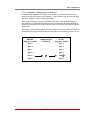
5.1. The Plug Status Screen (Text Interface; MPC-20V Shown)
. . . . . . . . . . . . . . . . . . . . . . . . 5-2
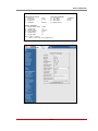
5.2. The Home Screen (Web Browser Interface) . . . . . . . . . . . . . . . . . . . . . . . . . . . . . . . . . . . .
5-3
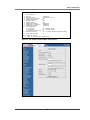
5.3. The System Parameters Menu (Text Interface) . . . . . . . . . . . . . . . . . . . . . . . . . . . . . . . . . .
5-6
5.4. The System Parameters Menu (Web Browser Interface) . . . . . . . . . . . . . . . . . . . . . . . . . .
5-6
5.5. The Add User Menu (Text Interface) . . . . . . . . . . . . . . . . . . . . . . . . . . . . . . . . . . . . . . . . .
5-23
5.6. The Add User Menu (Web Browser Interface)
. . . . . . . . . . . . . . . . . . . . . . . . . . . . . . . . . 5-23
5.7. The Add Plug to Group Menu (Text Interface)
. . . . . . . . . . . . . . . . . . . . . . . . . . . . . . . . . 5-31
5.8. The Add Plug Groups Menu (Web Browser Interface) . . . . . . . . . . . . . . . . . . . . . . . . . . .
5-31
5.9. The Plug Parameters Menu (Text Interface)
. . . . . . . . . . . . . . . . . . . . . . . . . . . . . . . . . . . 5-35
5.10. The Plug Parameters Menu (Web Browser Interface)
. . . . . . . . . . . . . . . . . . . . . . . . . . . 5-35
5.11. Boot Priority Example 1 . . . . . . . . . . . . . . . . . . . . . . . . . . . . . . . . . . . . . . . . . . . . . . . . . . . 5-38
5.12. Boot Priority Example 2 . . . . . . . . . . . . . . . . . . . . . . . . . . . . . . . . . . . . . . . . . . . . . . . . . . . 5-39
5.13. Serial Port Configuration Menu (Text Interface)
. . . . . . . . . . . . . . . . . . . . . . . . . . . . . . . . 5-40
5.14. Port Configuration Menu (Web Browser Interface) . . . . . . . . . . . . . . . . . . . . . . . . . . . . . .
5-40
5.15. Remote/AUX Port Configuration Menu (Text Interface)
. . . . . . . . . . . . . . . . . . . . . . . . . . 5-44
5.16. Remote/AUX Port Configuration Menu (Web Browser Interface) . . . . . . . . . . . . . . . . . . .
5-44
5.17. Network Parameters Menu (Text Interface) . . . . . . . . . . . . . . . . . . . . . . . . . . . . . . . . . . . .
5-47
5.18. Network Configuration Menu (Web Browser Interface)
. . . . . . . . . . . . . . . . . . . . . . . . . . 5-47
9.1. The Help Menu (Administrator Mode; Text Interface) . . . . . . . . . . . . . . . . . . . . . . . . . . . . . 9-4
11.1. The Test Menu (Text Interface, Administrator Mode Only) . . . . . . . . . . . . . . . . . . . . . . . .
11-2
14.1. Web Access Parameters (Text Interface Only) . . . . . . . . . . . . . . . . . . . . . . . . . . . . . . . . . 14-1
B.1. RS232 Console Port Interface
. . . . . . . . . . . . . . . . . . . . . . . . . . . . . . . . . . . . . . . . . . . . Apx-2
B.2. MPC Series AUX Port Interface . . . . . . . . . . . . . . . . . . . . . . . . . . . . . . . . . . . . . . . . . . . . Apx-3
C.1. DX9F-WTI-RJ Snap Adapter Interface . . . . . . . . . . . . . . . . . . . . . . . . . . . . . . . . . . . . . . . Apx-
4
C.2. Connecting
an Optional MPC Auxilliary unit to the MPC Master Unit . . . . . . . . . . . . . . Apx-4
C.3. Connecting
an Optional MPC-DISPLAY Unit to an MPC Series Master Unit . . . . . . . . . Apx-5
C.4. Connecting RJ-45 DCE Devices to the AUX & Remote Ports
. . . . . . . . . . . . . . . . . . . . Apx-6
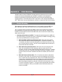
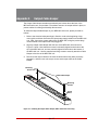
E.1. Mounting Holes; MPC-20V Back Panel
. . . . . . . . . . . . . . . . . . . . . . . . . . . . . . . . . . . . . Apx-9
E.2.
Attaching the "L" Brackets to the Equipment Rack (MPC-20V Shown) . . . . . . . . . . . . . Apx-9
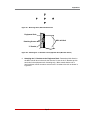
E.3.
Attaching Mounting Buttons to MPC-20V (Vertical) Units . . . . . . . . . . . . . . . . . . . . . . Apx-10
E.4.
Mounting Button Holes . . . . . . . . . . . . . . . . . . . . . . . . . . . . . . . . . . . . . . . . . . . . . . . . . Apx-10
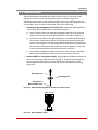
E.5.
Attaching the Hook Brackets to the Equipment Rack . . . . . . . . . . . . . . . . . . . . . . . . . Apx-11
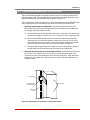
E.6. Zero-U Pocket Brackets (Cross Section; Nested in Pocket)
. . . . . . . . . . . . . . . . . . . . Apx-12
E.7.
Zero-U Pocket Brackets (Cross Section; Outside Pocket to Allow Cable Cavity) . . . . Apx-12
F.1.
Installing the Output Cable Keeper (MPC-20V Series Units Only) . . . . . . . . . . . . . . . . Apx-13

1-1
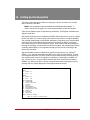
1. Introduction
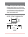
WTI’s MPC series Managed Power Controllers allow secure, remote metering and
management of AC powered rack mount equipment via SSL, SSH, SNMP, web
browser, telnet, external modem or local terminal. The MPC can monitor power to your
equipment, and automatically notify you when changes in current levels, temperature,
circuit breaker status or other factors exceed user-defined threshold values.
The MPC features two separate power circuits with up to 20 Amps input feed handling
capacity per branch circuit, and is available in a horizontal, rack mount version with
eight or sixteen switched outlets, or as a “zero unit” vertical mount model with 20
switched outlets.
Power Metering and Management:
The MPC can constantly measure current consumption, temperature levels, ping
response and other factors. If the MPC detects that user defined thresholds for these
values have been exceeded, the unit can promptly notify you via email, SNMP, Syslog,
LED or audible alarm. When temperature and current readings exceed user defined
critical values, the MPC can also intelligently shed the current load by temporarily
shutting down nonessential devices; when readings return to acceptable levels, the
MPC can restore power to those devices to return to normal operating conditions.
In addition, the MPC can also notify you when the Invalid Access Lockout has
been triggered, when one of the MPC circuit breakers is open, or when a loss of
communication with the optional auxiliary units is detected. The MPC also records
current consumption data to a convenient log file, which can be retrieved in ASCII, XML,
or CSV format or displayed in graph format.
Security and Co-Location Features:
Secure Shell (SSHv2) encryption and address-specific IP security masks help to prevent
unauthorized access to command and configuration functions.
The MPC also provides four different levels of security for user accounts: Administrator,
SuperUser, User and ViewOnly. The Administrator level provides complete access to
all plug functions, operating features and configuration menus. The SuperUser level
allows switching and rebooting of all plugs but does not allow access to configuration
functions. The User level allows access to only a select group of Administrator-defined
plugs. The ViewOnly level allows you to check plug status and unit status, but does not
allow switching or rebooting of outlets or access to configuration menus.
The MPC includes full Radius support, LDAP capability, TACACS capability, DHCP
and an invalid access lockout feature. An Audit Log records all user access, login and
logout times and command actions.

1-2
Introduction
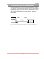
Convenient, Durable Design:
The MPC is available with an optional remote display panel, which can be used to show
the status of MPC units installed in hard-to-reach spots, deep inside equipment racks.
When additional outlets are needed, each MPC unit can also be connected to up to
three Auxiliary/Remote MPC units, allowing control of up to 80 outlets via a single IP
Address .
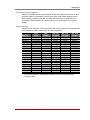
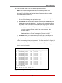
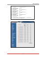
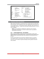
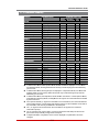
Model Numbers
The MPC series includes a variety of horizontal and vertical models to accommodate the
power distribution needs of almost any rack mount application.
Model No.
Input
Feeds
Input
Voltage
Max. Load
per Outlet
Max. Load
per Input
Max. Load
per Unit
MPC-8H-1 2 ea, 20 Amp 100 to 120 VAC 16 Amps 16 Amps * 32 Amps *
MPC-8H-2
2 ea, 16 Amp 100 to 240 VAC 10 Amps 16 Amps * 32 Amps *
MPC-16H-1
2 ea, 20 Amp 100 to 120 VAC 16 Amps 16 Amps * 32 Amps *
MPC-16H-2
2 ea, 16 Amp 100 to 240 VAC 10 Amps 16 Amps * 32 Amps *
MPC-18H-1
1 ea, 20 Amp 100 to 120 VAC 16 Amps 16 Amps * 16 Amps *
MPC-18H-2
1 ea, 16 Amp 100 to 240 VAC 10 Amps 16 Amps * 16 Amps *
MPC-20V-1
2 ea, 20 Amp 100 to 120 VAC 16 Amps 16 Amps * 32 Amps *
MPC-20V-2
2 ea, 16 Amp 100 to 240 VAC 15 Amps 16 Amps * 32 Amps *
MPC-20VS20-1
1 ea, 20 Amp 100 to 120 VAC 16 Amps 16 Amps * 16 Amps *
MPC-20VS20-2
1 ea, 16 Amp 100 to 240 VAC 15 Amps 16 Amps * 16 Amps *
MPC-20VD20-1
2 ea, 20 Amp 100 to 120 VAC 16 Amps 16 Amps * 32 Amps *
MPC-20VD20-2
2 ea, 20 Amp 100 to 240 VAC 15 Amps 16 Amps * 32 Amps *
MPC-20VS30-1
1 ea, 30 Amp 100 to 120 VAC 20 Amps 24 Amps * 24 Amps *
MPC-20VS30-2
1 ea, 30 Amp 100 to 240 VAC 15 Amps 24 Amps * 24 Amps *
MPC-20VD30-1
2 ea, 30 Amp 100 to 120 VAC 20 Amps 24 Amps * 48 Amps *
MPC-20VD30-2
2 ea, 30 Amp 100 to 240 VAC 15 Amps 24 Amps * 48 Amps *
MPC-20VS16-3
1 ea, 16 Amp 100 to 240 VAC 10 Amps 16 Amps 16 Amps
MPC-20VD16-3
2 ea, 16 Amp 100 to 240 VAC 10 Amps 16 Amps 32 Amps
MPC-20VS32-3
1 ea, 32 Amp 100 to 240 VAC 10 Amps 32 Amps 32 Amps
MPC-20VD32-3
2 ea, 32 Amp 100 to 240 VAC 10 Amps 32 Amps 64 Amps
* In accordance with UL requirements for branch circuits, this value has been
de-rated to 80%.

1-3
Introduction
Typographic Conventions
^ (e.g. ^X) Indicates a control character. For example, the text "^X" (Control X)
indicates the [Ctrl] key and the [X] key must be pressed
simultaneously.
COURIER FONT Indicates characters typed on the keyboard.
For example, /AC or /ON A2.
[Bold Font] Text set in bold face and enclosed in square brackets indicates a
specific key. For example, [Enter] or [Esc].
< > Indicates required keyboard entries. For Example: /P <n>.
[ ] Indicates optional keyboard entries. For Example: /P [n].

2-1
2. Unit Description
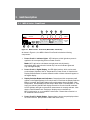
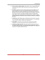
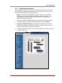
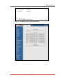
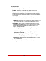
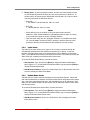
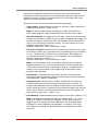
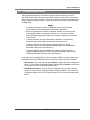
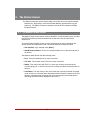
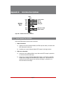
2.1. MPC-H Series - Front Panel
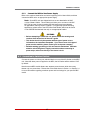
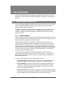
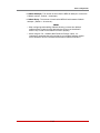
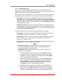
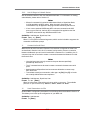
As shown in Figure 2.1, the MPC-H Series Front Panel includes the following
components:
1.
Power Circuit A - Indicator Lights: LED indicators, which light when power is
applied to the corresponding outlet on Power Circuit A.
Note: MPC-18H series units feature a single power circuit (branch.)
Accordingly, MPC-18H units also include only one set of Indicator lights and
only one Digital Display.
2. Power Circuit A - Digital Display: An LED digital readout, which can be used
to show Amps, Kilowatts, Volts or Temperature for Power Circuit A. Note that the
Display Selection Button is used to determine which of these values will appear on
the digital display..
3. Display Selection Button and Indicators: Determines which measurement will
appear on the Digital Displays for Circuits A and B. Each time the Display Selection
Button is pressed, the Digital Displays will toggle between Amps, Kilowatts, Volts,
Temperature, Total Kilowatts and Total Amps. When either "Total Kilowatts" or "Total
Amps" are selected, the MPC will display the total for Circuits A and B combined.
An LED indicator will light to show which measurement is currently selected. Note
that the "Total Kilowatts" and "Total Amps" displays are not available on
MPC-H series units, or on some MPC-V series units. Please refer to Section 2.4
for additional button functions.
4. Power Circuit B - Digital Display: Same as Item 2 above, except displays values
for Power Circuit B. (Not present on MPC-18H series units.)
8.8.8
8.8.8
REMOTE
www.wti.com
MPC-16H
Managed Power
Controller
AUX 1
AUX 2 AUX 3 CONSOLE PORT
AUDIBLE
ALARM
DEFAULT
ON
INPUT A
PLUGS
PLUGS
INPUT B
A1 A2 A3 A4
A5 A6 A7 A8
B1 B2 B3 B4
B5 B6 B7 B8
DISPLAY
SELECTION
AMPS KWATTS
VOLTS
TEMP
1
2
3
4
5
6
7
8 9
Figure 2.1: MPC-H Series - Front Panel (Model MPC-16H Shown)

2-2
Unit Description
5. Power Circuit B - Indicator Lights: Same as Item 1 above, except the LEDs light
to indicate On/Off status of Power Circuit B outlets. (Not present on MPC-18H
series units.).
6. Link Ports: Four RJ45 connectors, which can be used to link the MPC unit to up
to three other MPC units, plus the optional MPC-DISPLAY, status display panel.
When your MPC unit is linked to other MPC units, this allows control of up to four
MPC units (one local unit, plus three remote units) via one IP address. If necessary,
the Link Ports can also be reconfigured as RS232 serial ports (as described in
Section 5.8.2) to allow communication with attached devices. The MPC includes
three AUX Ports and one Remote Port; the remote port is intended for connection to
the MPC-DISPLAY unit, and the AUX Ports are intended for connection to additional
MPC units.
7. Console Port: A DB9, RS232 serial port (DTE), which can be used for connection
to a local terminal or external modem, as described in Section 4. For a description
of the Console Port interface, please refer to Appendix B.1.
8. Default Button: This button can be used to either reset the unit to default
parameters or to perform several other functions, described in Section 2.4.
9. Audible Alarm Button and LED: When any of the Alarms discussed in Section 7
are triggered, this LED will light, and the MPC will emit an audible alarm signal. To
turn off the audible alarm single, press the Audible Alarm Button once. Please refer
to Section 2.4 for additional button functions.

2-3
Unit Description
BUS
A
BUS
B
BUS
A
BUS
B
A-1 A-2
A-3 A-4 A-5
A-6
A-7 A-8
B-1
B-2
B-3
B-4
B-5
B-6 B-7
B-8
10/100 BaseT
ACT
A
B
ALARM
LINK
1
3
4
3
2
6
5
7
8
6
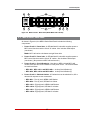
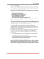
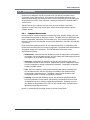
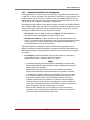
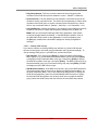
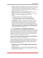
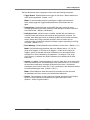
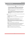
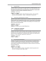
Figure 2.2: MPC-H Series - Back Panel (Model MPC-16H-1 Shown)
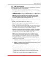
2.2. MPC-H Series - Back Panel
As shown in Figure 2.2, the MPC-H Series Back Panel includes the following
components:
1. Power Circuit A - Power Inlet: An IEC320-C20 AC inlet which supplies power to
MPC control functions and the Circuit “A” outlets. Also includes cable keeper
(not shown.)
Note: MPC-18H series units feature a single Power Inlet.
2. Power Circuit B - Power Inlet: An IEC320-C20 AC inlet which supplies power to
MPC control functions and the Circuit “B” outlets. Also includes cable keeper
(not shown.) (Not present on MPC-18H series units.)
3. Power Circuit A - Circuit Breaker(s): Note that on MPC-16H and MPC-18H
models, there are two circuit breakers for each power circuit. The circuit breakers
are rated as follows:
• MPC-8H-1, MPC-16H-1 and MPC-18H-1: 20 Amp Circuit Breaker(s).
• MPC-8H-2, MPC-16H-2 and MPC-18H-2: 16 Amp Circuit Breaker(s).
4. Power Circuit A - Switched Outlets: AC Outlets that can be switched On, Off or
rebooted in response to user commands:
• MPC-8H-1: Four (4) each, NEMA 5-20R Outlets.
• MPC-8H-2: Four (4) each, IEC320-C13 Outlets.
• MPC-16H-1: Eight (8) each, NEMA 5-20R Outlets.
• MPC-16H-2: Eight (8) each, IEC320-C13 Outlets.
• MPC-18H-1: Eight (8) each, NEMA 5-20R Outlets.
• MPC-18H-2: Eight (8) each, IEC320-C13 Outlets.

2-4
Unit Description
5. Power Circuit B - Switched Outlets: Same as Item 4 above. (Not present on
MPC-18H series units.)
6. Power Circuit B - Circuit Breaker(s): Same as Item 3 above. (Not present on
MPC-18H series units.)
7. Alarm Indicator Lights: Two LEDs which light when an alarm condition is detected
at the corresponding power circuit. For information on Alarm Configuration, please
refer to Section 7. Note that MPC-18H series units include only one Alarm Indicator
Light.
8. Network Port: An RJ45 Ethernet port for connection to your 100Base-T, TCP/IP
network. Note that the MPC features a default IP address (192.168.168.168). This
allows you to connect to the unit without first assigning an IP address. Note that the
Network Port also includes two, small LED indicators for Link and Data Activity. For
more information on Network Port configuration, please refer to Section 5.9.
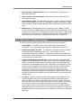
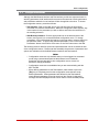
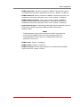
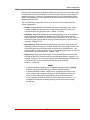
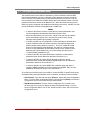
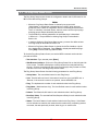
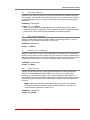
2.3. MPC-V Series - Hardware Description
As shown in Figure 2.3, MPC-V Series units include the following components:
1. Default Button: This button can be used to either reset the unit to default
parameters or to perform several other functions, as described in Section 2.4.
2. Audible Alarm Button and LED: Two LEDs which light when an alarm condition
is detected at the corresponding power circuit. For information on Alarm
Configuration, please refer to Section 7. Please refer to Section 2.4 for additional
button functions Note that MPC-V series units that include only one power inlet will
also include only one Alarm LED.
3. Display Selection Button and Indicators: Determines which measurement will
appear on the Digital Displays for Circuits A and B. Each time the Display Selection
Button is pressed, the Digital Displays will toggle between Amps, Kilowatts, Volts,
Temperature, Total Kilowatts and Total Amps. When either "Total Kilowatts" or "Total
Amps" are selected, the MPC will display the total for Circuits A and B combined.
An LED indicator will light to show which measurement is currently selected.
Please refer to Section 2.4 for additional button functions. Note that the "Total
Kilowatts and "Total Amps" displays are not available on all MPC-V series units, and
that MPC-V series units that include only one power inlet, will also include only one
Digital Display.
4. Link Ports: Four RJ45 connectors, which can be used to link the MPC unit to up
to three other MPC units, plus the optional MPC-DISPLAY, status display panel.
When your MPC unit is linked to other MPC units, this allows control of up to four
MPC units (one local unit, plus three remote units) via one IP address. If necessary,
the Link Ports can also be reconfigured as RS232 serial ports (as described in
Section 5.8.2) to allow communication with attached devices. The MPC includes
three AUX Ports and one Remote Port; the remote port is intended for connection to
the MPC-DISPLAY unit, and the AUX Ports are intended for connection to additional
MPC units.

2-5
Unit Description
Managed Power Controller
MPC-20V
8.8.8
8.8.8
OFF
ON
20
I
O
OFF
ON
20
I
O
OFF
ON
20
I
O
OFF
ON
20
I
O
DEFAULT
AUDIBLE
ALARM
ON
DISPLAY
SELECTION
AMPS
VOLTS
KWATTS
TOTAL A+B
KWATTS
AMPS
TEMP
ACT
LINK
AUX
1
AUX
3
REMOTE
DISPLAY
AUX
2
Ethernet
10/100
CONSOLE
A B
BRANCH
A1
BRANCH
A2
BRANCH
B1
BRANCH
B2
PLUG A1
PLUG A2
PLUG A3
PLUG A4
PLUG A5
PLUG A6
PLUG A7
PLUG A8
PLUG A9
PLUG A10
PLUG B1
PLUG B2
PLUG B3
PLUG B4
PLUG B5
PLUG B6
PLUG B7
PLUG B8
PLUG B9
PLUG B10
A1
A2 B1 B2
1 4
2 5
3 6
7
9 10
13
11
12
8
Figure 2.3: MPC-20V Series - Hardware Description (Model MPC-20VD20-1 Shown)

2-6
Unit Description
5. Network Port: An RJ45 Ethernet port for connection to your 100Base-T, TCP/IP
network. Note that the MPC features a default IP address (192.168.168.168). This
allows you to connect to the unit without first assigning an IP address. Note that the
Network Port also includes two, small LED indicators for Link and Data Activity. For
more information on Network Port configuration, please refer to Section 5.9.
6. Console Port: A DB9, RS232 serial port (DTE), which can be used for connection
to a local terminal or external modem, as described in Section 4. For a description
of the Console Port interface, please refer to Appendix B.1.
7. Power Circuit A - Digital Display: An LED digital readout, which can be used
to show Amps, Kilowatts, Volts or Temperature for Power Circuit A. Note that the
Display Selection Button (Item 3) is used to determine which of these values will
appear on the digital display.
Note: Some MPC models include only one power circuit. Accordingly, MPC
models that include only one power circuit, the unit will also have only one
digital display.
8. Power Circuit B - Digital Display: Same as Item 7 above, except displays values
for Power Circuit B. MPC Models that include only one power circuit will also have
only one digital display. (Not included on MPC-V series models that feature a single
power inlet.)
9. Power Circuit A - Switched Outlets and Indicator Lights: AC Outlets that can be
switched On, Off or rebooted in response to user commands. Note that each outlet
includes an LED Indicator, which lights when power is applied to the outlet.
Notes:
• Some MPC models include only one power circuit.
• Please refer to the table in Section 1 or Section 3 for power ratings for your
specific MPC model.
10. Power Circuit B - Switched Outlets and Indicator Lights: Same as Item 9 above,
except outlets and LED indicators are for Power Circuit B. Note that some MPC
models include only one power circuit. (Not included on MPC-V series models that
feature a single power inlet.)
11. Circuit Breaker(s): Some MPC models include two power circuits, with two
breakers for each circuit, and other MPC models include only one power circuit with
two circuit breakers. For a description of the power rating for your specific MPC
model, please refer to the table in Section 1 or Section 3.
12. Unit Bottom Plate: In all models except MPC-20V-1 and MPC-20V-2, the power
inlets are located on the bottom plate of the unit. In MPC-20V-1 and MPC-20V-2
models, the power inlets are located at the bottom of the front panel.

2-7
Unit Description
13. Power Inlet(s): The power inlets are configured differently on MPC models, in
accordance with the power rating, maximum load and the number of power circuits.
Depending on your specific model, the MPC may include either one or two power
inlets or either one or two power supply cables. Other MPC models may include
either one or two permanently attached power supply cables. For a description of
the power input configuration for your specific MPC unit, please fefer to the table in
Section 1 or Section 3. Note that MPC models with detachable power cable(s) will
also include a power inlet cable keeper.
2.4. Additional Button Functions
In addition to the button functions discussed in Sections 2.1, 2.2 and 2.3, the Default,
Audible Alarm and Display Selection buttons can also be used to perform several
additional functions described below:
Notes:
• All Front Panel Button functions can also be disabled via the System
Parameters menu, as described in Section 5.3.
• When the MPC is reset to factory defaults, all user-defined configuration
parameters will be cleared, and the default “super” user account will also be
restored.
1. Reboot Operating System:
a) Press and hold the Default button for five seconds, and then release it.
b) The MPC will reboot it's operating system; all plugs will be left in their current
On/Off state.
c) If the optional MPC-DISPLAY unit is installed, and this operation is performed at
the MPC-DISPLAY unit, all connected MPC units will also be rebooted.
2. Set Parameters to Factory Defaults:
a) Simultaneously press both the Default button and the Display Selection button,
hold them for five seconds, and then release them.
b) All MPC parameters will be reset to their original factory default settings, and
the unit will then reboot. All plugs will be left in their current On/Off state.
c) This function will not be applied to other connected MPC units.
3. Toggle/Default All Plugs:
a) Simultaneously press both the Default button and Audible Alarm button, hold
them for five seconds, and then release them.
b) The MPC will switch all plugs to the Off state. If all plugs are already in the Off
state, then the unit will reset all plugs to their user defined default states.
c) This function will not be applied to other connected MPC units.

2-8
Unit Description
4. Enable/Disable Audible Alarm:
a) In the default state, the Audible Alarm is Enabled.
b) To disable the Audible Alarm, press and hold the Audible Alarm button for three
seconds and then release it. To enable the Audible Alarm, press and hold the
Audible Alarm button for three seconds again.
c) If the optional MPC-DISPLAY unit is installed, and this operation is performed at
the MPC-DISPLAY unit, the audible alarm feature on all connected MPC units
will also be disabled. If this operation is performed at one of the connected
MPC units, then the operation will only be applied to that unit.
Page is loading ...
Page is loading ...
Page is loading ...
Page is loading ...
Page is loading ...
Page is loading ...
Page is loading ...
Page is loading ...
Page is loading ...
Page is loading ...
Page is loading ...
Page is loading ...
Page is loading ...
Page is loading ...
Page is loading ...
Page is loading ...
Page is loading ...
Page is loading ...
Page is loading ...
Page is loading ...
Page is loading ...
Page is loading ...
Page is loading ...
Page is loading ...
Page is loading ...
Page is loading ...
Page is loading ...
Page is loading ...
Page is loading ...
Page is loading ...
Page is loading ...
Page is loading ...
Page is loading ...
Page is loading ...
Page is loading ...
Page is loading ...
Page is loading ...
Page is loading ...
Page is loading ...
Page is loading ...
Page is loading ...
Page is loading ...
Page is loading ...
Page is loading ...
Page is loading ...
Page is loading ...
Page is loading ...
Page is loading ...
Page is loading ...
Page is loading ...
Page is loading ...
Page is loading ...
Page is loading ...
Page is loading ...
Page is loading ...
Page is loading ...
Page is loading ...
Page is loading ...
Page is loading ...
Page is loading ...
Page is loading ...
Page is loading ...
Page is loading ...
Page is loading ...
Page is loading ...
Page is loading ...
Page is loading ...
Page is loading ...
Page is loading ...
Page is loading ...
Page is loading ...
Page is loading ...
Page is loading ...
Page is loading ...
Page is loading ...
Page is loading ...
Page is loading ...
Page is loading ...
Page is loading ...
Page is loading ...
Page is loading ...
Page is loading ...
Page is loading ...
Page is loading ...
Page is loading ...
Page is loading ...
Page is loading ...
Page is loading ...
Page is loading ...
Page is loading ...
Page is loading ...
Page is loading ...
Page is loading ...
Page is loading ...
Page is loading ...
Page is loading ...
Page is loading ...
Page is loading ...
Page is loading ...
Page is loading ...
Page is loading ...
Page is loading ...
Page is loading ...
Page is loading ...
Page is loading ...
Page is loading ...
Page is loading ...
Page is loading ...
Page is loading ...
Page is loading ...
Page is loading ...
Page is loading ...
Page is loading ...
Page is loading ...
Page is loading ...
Page is loading ...
Page is loading ...
Page is loading ...
Page is loading ...
Page is loading ...
Page is loading ...
Page is loading ...
Page is loading ...
Page is loading ...
Page is loading ...
Page is loading ...
Page is loading ...
Page is loading ...
Page is loading ...
Page is loading ...
Page is loading ...
Page is loading ...
Page is loading ...
Page is loading ...
Page is loading ...
Page is loading ...
Page is loading ...
Page is loading ...
Page is loading ...
Page is loading ...
Page is loading ...
Page is loading ...
Page is loading ...
Page is loading ...
Page is loading ...
Page is loading ...
Page is loading ...
Page is loading ...
Page is loading ...
Page is loading ...
Page is loading ...
Page is loading ...
Page is loading ...
Page is loading ...
Page is loading ...
Page is loading ...
Page is loading ...
Page is loading ...
Page is loading ...
Page is loading ...
Page is loading ...
Page is loading ...
Page is loading ...
Page is loading ...
Page is loading ...
Page is loading ...
Page is loading ...
Page is loading ...
Page is loading ...
Page is loading ...
Page is loading ...
Page is loading ...
Page is loading ...
Page is loading ...
Page is loading ...
Page is loading ...
Page is loading ...
Page is loading ...
Page is loading ...
Page is loading ...
Page is loading ...
Page is loading ...
Page is loading ...
Page is loading ...
-
 1
1
-
 2
2
-
 3
3
-
 4
4
-
 5
5
-
 6
6
-
 7
7
-
 8
8
-
 9
9
-
 10
10
-
 11
11
-
 12
12
-
 13
13
-
 14
14
-
 15
15
-
 16
16
-
 17
17
-
 18
18
-
 19
19
-
 20
20
-
 21
21
-
 22
22
-
 23
23
-
 24
24
-
 25
25
-
 26
26
-
 27
27
-
 28
28
-
 29
29
-
 30
30
-
 31
31
-
 32
32
-
 33
33
-
 34
34
-
 35
35
-
 36
36
-
 37
37
-
 38
38
-
 39
39
-
 40
40
-
 41
41
-
 42
42
-
 43
43
-
 44
44
-
 45
45
-
 46
46
-
 47
47
-
 48
48
-
 49
49
-
 50
50
-
 51
51
-
 52
52
-
 53
53
-
 54
54
-
 55
55
-
 56
56
-
 57
57
-
 58
58
-
 59
59
-
 60
60
-
 61
61
-
 62
62
-
 63
63
-
 64
64
-
 65
65
-
 66
66
-
 67
67
-
 68
68
-
 69
69
-
 70
70
-
 71
71
-
 72
72
-
 73
73
-
 74
74
-
 75
75
-
 76
76
-
 77
77
-
 78
78
-
 79
79
-
 80
80
-
 81
81
-
 82
82
-
 83
83
-
 84
84
-
 85
85
-
 86
86
-
 87
87
-
 88
88
-
 89
89
-
 90
90
-
 91
91
-
 92
92
-
 93
93
-
 94
94
-
 95
95
-
 96
96
-
 97
97
-
 98
98
-
 99
99
-
 100
100
-
 101
101
-
 102
102
-
 103
103
-
 104
104
-
 105
105
-
 106
106
-
 107
107
-
 108
108
-
 109
109
-
 110
110
-
 111
111
-
 112
112
-
 113
113
-
 114
114
-
 115
115
-
 116
116
-
 117
117
-
 118
118
-
 119
119
-
 120
120
-
 121
121
-
 122
122
-
 123
123
-
 124
124
-
 125
125
-
 126
126
-
 127
127
-
 128
128
-
 129
129
-
 130
130
-
 131
131
-
 132
132
-
 133
133
-
 134
134
-
 135
135
-
 136
136
-
 137
137
-
 138
138
-
 139
139
-
 140
140
-
 141
141
-
 142
142
-
 143
143
-
 144
144
-
 145
145
-
 146
146
-
 147
147
-
 148
148
-
 149
149
-
 150
150
-
 151
151
-
 152
152
-
 153
153
-
 154
154
-
 155
155
-
 156
156
-
 157
157
-
 158
158
-
 159
159
-
 160
160
-
 161
161
-
 162
162
-
 163
163
-
 164
164
-
 165
165
-
 166
166
-
 167
167
-
 168
168
-
 169
169
-
 170
170
-
 171
171
-
 172
172
-
 173
173
-
 174
174
-
 175
175
-
 176
176
-
 177
177
-
 178
178
-
 179
179
-
 180
180
-
 181
181
-
 182
182
-
 183
183
-
 184
184
-
 185
185
-
 186
186
-
 187
187
-
 188
188
-
 189
189
-
 190
190
-
 191
191
-
 192
192
-
 193
193
-
 194
194
-
 195
195
-
 196
196
-
 197
197
-
 198
198
-
 199
199
-
 200
200
-
 201
201
-
 202
202
-
 203
203
-
 204
204


Western Telematic MPC-20V-1 MPC-8H-2 User manual
- Category
- Networking
- Type
- User manual
Ask a question and I''ll find the answer in the document
Finding information in a document is now easier with AI
Related papers
-
Western Telematic M User manual
-
 Western Telematic Switch CMS-16 User manual
-
WTI CMS-16 User manual
-
 Western Telematic APS-16 User manual
-
-
 Western Telematic PTS-8NE15-1 User manual
-
 Western Telematic Switch CAS-81 User manual
-
-
 Western Telematic IPS-15 User manual
-
WTI IPS-800, IPS-800-CE, IPS-1600, IPS-1600CE User manual


Other documents
-
Black Box SWI082 User manual
-
Black Box SW552A User guide
-
-
-
-
ICT ICT180S-12IRC Owner's manual
-
-
Raritan Computer DKX432 User manual
-
Raritan DOMINION KSX II User guide
-
Dukane iQ LS-E User manual