Page is loading ...

68-1844-02 Rev. B
09 14
HDMI DA Series
User Guide
HDMI
®
Distribution Amplifiers

Safety Instructions • English
WARNING: This symbol,
D
, when used on the product, is intended
to alert the user of the presence of uninsulated dangerous voltage
within the product’s enclosure that may present a risk of electric shock.
ATTENTION: This symbol,
I
, when used on the product, is
intended to alert the user of important operating and maintenance
(servicing) instructions in the literature provided with the equipment.
For information on safety guidelines, regulatory compliances, EMI/EMF
compatibility, accessibility, and related topics, see the Extron Safety and
Regulatory Compliance Guide, part number 68-290-01, on the Extron
website, www.extron.com.
Instructions de sécurité • Français
AVERTISSEMENT : Ce pictogramme,
D
, lorsqu’il est utilisé sur
le produit, signale à l’utilisateur la présence à l’intérieur du boîtier du
produit d’une tension électrique dangereuse susceptible de provoquer
un choc électrique.
ATTENTION : Ce pictogramme,
I
, lorsqu’il est utilisé sur
le produit, signale à l’utilisateur des instructions d’utilisation ou de
maintenance importantes qui se trouvent dans la documentation
fournie avec le matériel.
Pour en savoir plus sur les règles de sécurité, la conformité à la
réglementation, la compatibilité EMI/EMF, l’accessibilité, et autres sujets
connexes, lisez les informations de sécurité et de conformité Extron,
réf. 68-290-01, sur le site Extron, www.extron.com.
Sicherheitsanweisungen • Deutsch
WARNUNG: Dieses Symbol
D
auf dem Produkt soll den Benutzer
darauf aufmerksam machen, dass im Inneren des Gehäuses dieses
Produktes gefährliche Spannungen herrschen, die nicht isoliert sind
und die einen elektrischen Schlag verursachen können.
VORSICHT: Dieses Symbol
I
auf dem Produkt soll dem Benutzer
in der im Lieferumfang enthaltenen Dokumentation besonders wichtige
Hinweise zur Bedienung und Wartung (Instandhaltung) geben.
Weitere Informationen über die Sicherheitsrichtlinien, Produkthandhabung,
EMI/EMF-Kompatibilität, Zugänglichkeit und verwandte Themen finden Sie
in den Extron-Richtlinien für Sicherheit und Handhabung (Artikelnummer
68-290-01) auf der Extron-Website, www.extron.com.
Instrucciones de seguridad • Español
ADVERTENCIA: Este símbolo,
D
, cuando se utiliza en el producto,
avisa al usuario de la presencia de voltaje peligroso sin aislar dentro del
producto, lo que puede representar un riesgo de descarga eléctrica.
ATENCIÓN: Este símbolo,
I
, cuando se utiliza en el producto,
avisa al usuario de la presencia de importantes instrucciones de uso y
mantenimiento recogidas en la documentación proporcionada con el
equipo.
Para obtener información sobre directrices de seguridad, cumplimiento
de normativas, compatibilidad electromagnética, accesibilidad y temas
relacionados, consulte la Guía de cumplimiento de normativas y seguridad
de Extron, referencia 68-290-01, en el sitio Web de Extron,
www.extron.com.
Инструкция по технике безопасности • Русский
ПРЕДУПРЕЖДЕНИЕ: Данный символ,
D
, если указан
на продукте, предупреждает пользователя о наличии
неизолированного опасного напряжения внутри корпуса
продукта, которое может привести к поражению электрическим
током.
ВНИМАНИЕ: Данный символ,
I
, если указан на продукте,
предупреждает пользователя о наличии важных инструкций по
эксплуатации и обслуживанию в руководстве, прилагаемом к
данному оборудованию.
Для получения информации о правилах техники безопасности,
соблюдении нормативных требований, электромагнитной
совместимости (ЭМП/ЭДС), возможности доступа и других вопросах
см. руководство по безопасности и соблюдению нормативных
требований Extron на сайте Extron: www.extron.com, номер по
каталогу - 68-290-01.
Chinese Simplified(简体中文)
警告: D产品上的这个标志意在警告用户该产品机壳内有暴露的危险 电压,
有触电危险。
注意:I 产品上的这个标志意在提示用户设备随附的用户手册中有
重要的操作和维护(维修)说明。
关于我们产品的安全指南、遵循的规范、EMI/EMF 的兼容性、无障碍
使用的特性等相关内容,敬请访问 Extron 网站 www.extron.com,参见 Extron
安全规范指南,产品编号 68-290-01。
Chinese Traditional( )
警告: D 若產品上使用此符號,是為了提醒使用者,產品機殼內存在著
可能會導致觸電之風險的未絕緣危險電壓。
注意I 若產品上使用此符號,是為了提醒使用者,設備隨附的用戶手冊中有重要
的 操 作 和 維 護( 維 修 )説 明 。
有關安全性指導方針、法規遵守、EMI/EMF 相容性、存取範圍和相關主題的詳細資訊,
請瀏覽 Extron 網站:www.extron.com,然後參閱《Extron 安全性與法規遵守手
冊》,準則編號 68-290-01。
Japanese
警告: この記号 D が製品上に表示されている場合は、筐体内に絶縁されて
いない高電圧が流れ、感電の危険があることを示しています。
注意:この記号 I が 製 品 上 に 表 示 さ れ て い る 場 合 は 、本 機 の 取 扱 説 明 書 に 記 載 さ れ て
いる重要な操作と保守(整備)の指示についてユーザーの注意を喚起するものです。
安全上のご注意、法令遵守、EMI/EMF適合性、その他の関連項目に
つ い て は 、エ ク スト ロ ン の ウ ェブ サ イト www.extron.com より
『Extron Safety and Regulatory Compliance Guide』 (P/N 68-290-01) をご覧く
ださい。
Korean
경고: 이 기호 D, 가 제품에 사용될 경우, 제품의 인클로저 내에 있는
접지되지 않은 위험한 전류로 인해 사용자가 감전될 위험이 있음을
경고합니다.
주의: 이 기호 I, 가 제품에 사용될 경우, 장비와 함께 제공된 책자에 나와
있는 주요 운영 및 유지보수(정비) 지침을 경고합니다.
안전 가이드라인, 규제 준수, EMI/EMF 호환성, 접근성, 그리고 관련 항목에 대한
자세한 내용은 Extron 웹 사이트(www.extron.com)의 Extron 안전 및 규제 준수
안내서, 68-290-01 조항을 참조하십시오.
Safety Instructions

FCC Class A Notice
This equipment has been tested and found to comply with the limits for a Class A digital
device, pursuant to part15 of the FCC rules. The ClassA limits provide reasonable protection
against harmful interference when the equipment is operated in a commercial environment.
This equipment generates, uses, and can radiate radio frequency energy and, if not installed
and used in accordance with the instruction manual, may cause harmful interference to radio
communications. Operation of this equipment in a residential area is likely to cause interference.
This interference must be corrected at the expense of the user.
NOTES:
• This unit was tested with shielded I/O cables on the peripheral devices. Shielded
cables must be used to ensure compliance with FCC emissions limits.
• For more information on safety guidelines, regulatory compliances, EMI/EMF
compatibility, accessibility, and related topics, see the Extron Safety and
Regulatory Compliance Guide on the Extron website.
Copyright
© 2014 Extron Electronics. All rights reserved.
Trademarks
All trademarks mentioned in this guide are the properties of their respective owners.
The following registered trademarks(
®
), registered service marks(
SM
), and trademarks(
TM
) are the property of
RGBSystems, Inc. or Extron Electronics:
Registered Trademarks
(
®
)
AVTrac, Cable Cubby, CrossPoint, eBUS, EDID Manager, EDID Minder, Extron, Flat Field, GlobalViewer, Hideaway, Inline, IPIntercom,
IPLink, Key Minder, LockIt, MediaLink, PlenumVault, PoleVault, PowerCage, PURE3, Quantum, SoundField, SpeedMount, SpeedSwitch,
SystemINTEGRATOR, TeamWork, TouchLink, V-Lock, VersaTools, VN-Matrix, VoiceLift, WallVault, WindoWall, XTP, XTP Systems
Registered Service Mark
(SM)
: S3 Service Support Solutions
Trademarks
(
™
)
AAP, AFL (Accu-Rate Frame Lock), ADSP (Advanced Digital Sync Processing), Auto-Image, CableCover, CDRS (Class D Ripple Suppression),
DDSP (Digital Display Sync Processing), DMI (Dynamic Motion Interpolation), DriverConfigurator, DSPConfigurator, DSVP (Digital Sync
Validation Processing), EQIP, FastBite, FOXBOX, Global Configurator, IP Intercom HelpDesk, LinkLicense, MAAP, MicroDigital, ProDSP, QS-FPC
(QuickSwitch Front Panel Controller), Scope-Trigger, SIS, Simple Instruction Set, Skew-Free, SpeedNav, Triple-Action Switching, XTRA,
ZipCaddy, ZipClip

Conventions Used in this Guide
Notifications
In this user guide, the following are used:
WARNING: Potential risk of severe injury or death.
AVERTISSEMENT : Risque potentiel de blessure grave ou de mort.
ATTENTION:
• Risk of property damage.
• Risque de dommages matériels.
NOTE: A note draws attention to important information.
TIP: A tip provides a suggestion to make working with the application easier.
Software Commands
Commands are written in the fonts shown here:
^AR Merge Scene,,Op1 scene 1,1 ^B 51 ^W^C
[01] R 0004 00300 00400 00800 00600 [02] 35 [17] [03]
E
X!
*
X1&
*
X2)
*
X2#
*
X2!
CE
}
NOTE: For commands and examples of computer or device responses mentioned
in this guide, the character “0” is used for the number zero and “O” represents the
capital letter “o”.
Computer responses and directory paths that do not have variables are written in the font
shown here:
Reply from 208.132.180.48: bytes=32 times=2ms TTL=32
C:\Program Files\Extron
Variables are written in slanted form as shown here:
ping xxx.xxx.xxx.xxx —t
SOH R Data STX Command ETB ETX
Selectable items, such as menu names, menu options, buttons, tabs, and field names are
written in the font shown here:
From the File menu, select New.
Click the OK button.
Specifications Availability
Product specifications are available on the Extron website, www.extron.com.

Contents
Introduction............................................................ 1
About the HDMI DA2, HDMI DA4, and
HDMI DA6 ......................................................... 1
Features ............................................................. 1
Application Diagram ........................................... 2
Installation .............................................................. 3
Installation Overview ........................................... 3
Rear Panel Features ........................................... 4
Connecting Power .............................................. 4
Connecting the Power Supply
(HDMI DA2 Only) ........................................... 5
Connecting the Input Source .............................. 7
Connecting the Output Displays ......................... 7
Wiring for RS-232 Control (Optional) ................... 8
Connecting to the USB Port ............................... 9
Operation .............................................................. 11
Front Panel Features ......................................... 11
Power Status LED ........................................ 11
USB Config Port ........................................... 12
Signal Status LEDs ....................................... 12
HDCP LEDs .................................................. 12
EDID LED ..................................................... 12
EDID Minder ..................................................... 13
Factory EDID ................................................ 13
Output EDID ................................................. 13
User Slots ..................................................... 13
HDMI DA2, HDMI DA4, and
HDMI DA6 EDID Lookup Table .................... 14
Mounting ............................................................... 16
Desktop Placement .......................................... 16
Rack Mounting ................................................. 16
UL Guidelines for Rack Mounting .................. 16
Rack Mounting Procedure ............................ 16
Under-desk Mounting ....................................... 16
SIS Commands ................................................... 17
Introduction to SIS ........................................... 17
Host-to-Distribution Amplifier
Communications ......................................... 17
Distribution Amplifier-initiated Messages ....... 17
Symbols Used in this Guide .............................. 18
Error Messages ............................................ 19
Command and Response Table for SIS
Commands ..................................................... 19
Updating Firmware ............................................ 21
Downloading and Installing Firmware Loader .... 21
Downloading HDMI DA Series Firmware ........... 22
Loading the Firmware to the
Distribution Amplifier ........................................ 23
HDMI DA Series • Contents v

HDMI DA Series • Contents vi

Introduction
This guide describes the function, installation, and operation of the HDMI DA2, HDMI DA4,
and HDMIDA6. Unless otherwise stated, the terms “distribution amplifier,” “DA,” or “HDMI DA
Series” refer to any of these distribution amplifiers.
This section provides the following information:
• About the HDMI DA2, HDMI DA4, and HDMI DA6
• Features
• Application Diagram
About the HDMI DA2, HDMI DA4, and HDMI DA6
These Extron distribution amplifiers distribute one HDMIinput signal to two (HDMI DA2),
four (HDMI DA4), or six (HDMI DA6) simultaneous outputs. All three models are fully
High-bandwidth Digital Content Protection (HDCP) compliant.
These distribution amplifiers support data rates up to 6.75 Gbps (2.25 Gbps per color) with up
to 12-bit deep color and use the EDID Minder feature for EDID management.
The automatic output compatibility correction feature scans each output device to ensure that
the output signal is compatible with the color depth and format requirements of the device.
Each output is adjusted independently.
Features
HDMI signal distribution — distributes one HDMI input to two (HDMI DA2), four (HDMIDA4),
or six (HDMI DA6) simultaneous HDMI video and embedded multi-channel digital audio signal
outputs. Supported HDMI specification features include data rates up to 6.75 Gbps, Deep
Color up to 12-bit, 3D, Lip Sync, and HD lossless audio formats.
Supports high-resolution video — including computer-video to 1920x1200, HDTV
1080p/60 and 2K.
HDCP compliant
Key Minder — continuously verifies HDCP compliance. Key Minder authenticates and
maintains continuous HDCP encryption between all input and output devices to enable
simultaneous distribution of a single source signal to multiple displays.
EDID Minder — automatically manages EDID communication between connected
devices. EDID Minder ensures that the source powers up properly and reliably outputs
content for display. This feature allows the user to assign EDID to the input from a list of
48factory-loaded EDID files, one of the connected display devices, or from a custom user slot:
• Factory EDID: 48 unique EDID files categorized by video format, resolution, and audio
support.
• Outputs: automatically stores the EDID of the display connected to the specified output.
• User slots: EDID is saved from an output or imported from a PC.
Automatic input cable equalization — up to 50 feet at 1080p/60 with 8-bit color when
used with Extron HDMI Pro Series cable. Actively conditions incoming HDMI signals to
compensate for signal loss when using long cables, low quality cables, or source devices with
poor signal output.
HDMI DA Series • Introduction 1

Output Compatibility Correction — monitoring the EDID of each connected display allows
the distribution amplifier to ensure the EDID is compatible with the current input signal. The
following adjustments are made for each output independently:
• Interface format: If the connected display is DVI and the input signal is HDMI, the signal
is reformatted to DVI. If the output is HDMI and the input is DVI, no reformatting is needed
because HDMI is backwards compatible with DVI.
• Video color bit depth: If the connected output device does not support the color
bit depth of the input signal, it is truncated down to the next level that is supported
(12-bit>10-bit > 8-bit). The signal can be forced to always truncate to 8-bit via Simple
Instruction Set (SIS) commands, disabling deep color.
Output muting via RS-232 — Provides the capability to mute one or all outputs at any
time. This allows content to be viewed on a local monitor prior to appearing on the main
presentation display.
Signal Status LEDs for the input and each output — provide real-time feedback and
monitoring of signal presence and HDCP authentication. The bi-color EDID LED indicator
notifies whether an internal or external EDID is stored.
Easy setup and commissioning — using the Extron PCS (Product Configuration Software),
which allows multiple products to be configured using a single software application.
Easy mounting options — The HDMI DA2 is a quarter rack wide, 1 inch high, and 3 inches
deep. The HDMI DA4 and HDMI DA6 are a half rack wide, 1 U high, and 6 inches deep. All
three models can be conveniently mounted in standard racks or under furniture.
Application Diagram
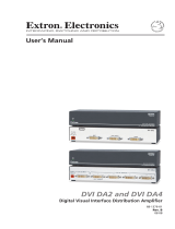
This diagram shows a typical application for the HDMI DA4. The other models can be used in
similar applications.
50/60 Hz
100-240V ~ 0.3 A MAX
HDMI DA4
RS-232
4321
Tx Rx G
REMOTEOUTPUTSINPUT
1
3
1
4
2
31
42
3
1
4
2
2
3
100
LINK
ACT
COM
IR
INPUT
RELAY
TX RX
R
IPL 250
®
ON
OFF
DISPLAY
MUTE
SCREEN
UP
SCREEN
DOWN
VCR
DVD
DOC
CAM
LAPTOP
PC
Blu-ray Player
Extron
HDMI DA4
Distribution
Amplier
HDMI
Cables
RS-232
TCP/IP
TouchLink
Control
System
Flat Panel Displays
Figure 1. Application Diagram
HDMI DA Series • Introduction 2

Installation
This section of the guide describes the following topics concerned with the installation and
setup of the HDMI DA2, HDMI DA4, and HDMI DA6 distribution amplifiers.
• Installation Overview
• Rear Panel Features
• Connecting Power
• Connecting the Input Source
• Connecting Output Displays
• Wiring for RS-232 Control
• Connecting to the USB Port
Installation Overview
To install and set up these distribution amplifiers, follow these instructions:
1. Mount the Distribution Amplifier in a suitable location (see page 16).
2. HDMI DA2 only: Connect the provided 12 VDC, 1 A power supply (see page 5).
3. HDMI DA4 and HDMI DA6 only: Connect to a 100-240 VAC (50 or 60 Hz) power
source using the provided IEC power cord (see page 4).
4. Connect and power on the display devices (see page7).
5. If configuration using SIS commands is required (see page 17), connect a control PC
to the rear panel captive screw connector (see page8) or the front panel USB port
(see page9).
6. Connect and power on the input device (see page 7).
HDMI DA Series • Installation 3

Rear Panel Features
RS
-23
2
Tx R
x
G
INPUT
REM
O
T
E
O
UTPUT
S
POWE
R
12V
0
.4
A
MAX
RS-232
Tx Rx G
12
INPUT
REMOTE
OUTPUTS
POWER
12V
0.4A MAX
AAC
CDDE
E
HDMI DA2
BBC
CE
E
50/60 H
z
1
00
-24
0
V ~
0
.
3
A MA
X
HDMI
DA
4
R
S
-232
Tx
Rx
G
REM
O
T
E
O
UTPUT
S
INPUT
50/60 Hz
100-240V ~ 0.3A MAX
HDMI DA4
RS-232
4321
Tx Rx G
REMOTEOUTPUTSINPUT
DD
HDMI DA4
50
/
60 H
z
1
00
-24
0
V ~
0
.
3
A MA
X
HDMI
DA6
R
S
-232
4
3
6
5
2
1
T
x
R
x
G
O
UTPUT
S
REM
O
T
E
INPUT
50/60 Hz
100-240V ~ 0.3A MAX
HDMI DA6
RS-232
4
36
521
Tx Rx G
OUTPUTS REMOTEINPUT
BBC
CE
E
DD
HDMI DA6
Figure 2. HDMI DA2 (top), HDMI DA4 (middle) and HDMI DA6 (bottom)
A
Power supply connector (see page 5)
B
IEC connector (see below)
C
HDMI input connector (see page 7)
D
HDMI output connectors (see page 7)
E
RS-232 connectors (see page 8)
Connecting Power
Connect a 100-240 VAC (50 or 60 Hz) power source, to the IEC connector of the HDMI DA4
or HDMI DA6 (figure 2,
B
, above), using the provided female IEC cable.
Connect the HDMI DA2 to the provided 12 VDC, 1 A power supply as described in
Connecting the Power Supply (HDMI DA2 Only) on the next page.
HDMI DA Series • Installation 4

Connecting the Power Supply (HDMI DA2 Only)
ATTENTION:
• This product is intended for use with a UL Listed power source marked “Class 2”
or “LPS” and rated 12VDC, maximum 1.0 A. Always use a power supply provided
by or specified by Extron. Use of an unauthorized power supply voids all regulatory
compliance certification and may cause damage to the supply and the end
product.
• Ce produit est destiné à une utilisation avec une source d’alimentation listéeUL
avec l’appellation «Classe2» ou «LPS» et normée 12Vcc, 1,0A maximum.
Utilisez toujours une source d’alimentation fournie ou recommandée par Extron.
L’utilisation d’une source d’alimentation non autorisée annule toute conformité
réglementaire et peut endommager la source d’alimentation ainsi que le produit
final.
• Extron power supplies are certified to UL/CSA 60950-1 and are classified as LPS
(Limited Power Source). Use of a non-LPS or unlisted power supply will void all
regulatory compliance certification.
• Les sources d’alimentation Extron sont qualifiées UL/CSA60950-1 et sont
classéesLPS(LimitedPowerSource). L’utilisation d’une source d’alimentation non-
listée ou non-listéeLPS annulera toute certification de conformité réglementaire.
• Unless otherwise stated, the AC/DC adapters are not suitable for use in air handling
spaces or in wall cavities. The power supply is to be located within the same vicinity
as the Extron AV processing equipment in an ordinary location, Pollution Degree 2,
secured to the equipment rack within the dedicated closet, podium, or desk.
• Sauf mention contraire, les adaptateurs AC/DC ne sont pas appropriés pour une
utilisation dans les espaces d’aération ou dans les cavités murales. La source
d’alimentation doit être située à proximité de l’équipement de traitement audiovisuel
dans un endroit ordinaire, avec un degré2 de pollution, fixé à un équipement de
rack à l’intérieur d’un placard, d’une estrade, ou d’un bureau.
• The installation must always be in accordance with the applicable provisions of
National Electrical Code ANSI/NFPA 70, article 725 and the Canadian Electrical
Code part 1, section 16. The power supply shall not be permanently fixed to
building structure or similar structure.
• Cette installation doit toujours être en accord avec les mesures qui s’applique
au National Electrical Code ANSI/NFPA70, article725, et au Canadian Electrical
Code, partie1, section16. La source d’alimentation ne devra pas être fixée de
façon permanente à une structure de bâtiment ou à une structure similaire.
HDMI DA Series • Installation 5

WARNING: The two power cord wires must be kept separate while the power supply
is plugged in. Remove power before wiring.
AVERTISSEMENT : Les deux cordons d’alimentation doivent être tenus à l’écart l’un
de l’autre quand l’alimentation est branchée. Couper l’alimentation avant de faire
l’installation électrique.
ATTENTION:
• The length of the exposed wires in the stripping process is critical. The ideal length
is 3/16 inches (5 mm). Any longer and the exposed wires may touch, causing a
short circuit between them. Any shorter and the wires can be easily pulled out even
if tightly fastened by the captive screws.
• La longueur des câbles exposés est primordiale lorsque l’on entreprend de les
dénuder. La longueur idéale est de 5mm (3/16inches). S’ils sont un peu plus
longs, les câbles exposés pourraient se toucher et provoquer un court circuit. S’ils
sont un peu plus courts, ils pourraient sortir, même s’ils sont attachés par les vis
captives.
• Do not tin the wire leads before installing into the connector. Tinned wires are not
as secure in the connector and could be pulled out.
• Ne pas étamer les conducteurs avant de les insérer dans le connecteur. Les
câbles étamés ne sont pas aussi bien fixés dans le connecteur et pourraient être
retirés.
1. Cut the DC output cord to the length needed.
2. Strip the jacket to expose 3/16 inch (5 mm) of the conductor
wire.
3. Verify the polarity of the wires.
4. Slide the exposed end into the captive screw connector and
secure by tightening the screw.
5. Use the supplied tie wrap to strap the power cord to the
extended tail of the connector.
6. Insert the captive screw connector into the rear panel
receptacle (Figure 2,
A
, on page 4).
7. Connect the power supply to a convenient 100-240 VAC
(50or 60 Hz) power source.
SECTION A–A
Ridges
Smooth
AA
3/16"
(5 mm) Max.
POWER
12V
0.4A MAX
HDMI DA Series • Installation 6

Connecting the Input Source
Use a HDMI cable to connect the input source to the female HDMI socket on the rear panel
(figure 2,
C
, on page 4).
The connectors are fully HDCP compliant. With cables up to 25 feet (7.6 m) they support
resolutions of up to 1080p @ 60 Hz with 12-bit color. With cables up to 50 feet (15.2 m) they
support 1080p or 1920x1200 @ 60 Hz with 8-bit color.
Follow these instructions to secure the input and
output HDMI connectors to the unit with the LockIt
HDMI lacing bracket provided:
1. Plug the HDMI cable into the panel connection.
2. Loosen the HDMI connection mounting screw
from the panel enough to allow the LockIt lacing
bracket to be placed over it. The screw does not
have to be removed.
3. Place the LockIt lacing bracket on the screw and
against the HDMI connector, then tighten the
screw to secure the bracket.
ATTENTION:
• Do not overtighten the HDMI
connection mounting screw. The shield
it fastens to is very thin and can easily
be stripped.
• Ne serrez pas trop la vis de montage
du connecteur HDMI. Le blindage
auquel elle est attachée est très fin et
peut facilement être dénudé.
4. Loosely place the included tie wrap around the HDMI connector and the LockIt lacing
bracket as shown.
5. While holding the connector securely against the lacing bracket, tighten the tie wrap, then
remove any excess length.
Connecting the Output Displays
Use a HDMI cable to connect up to two (HDMI DA2), four (HDMI DA4), or six (HDMI DA6)
output displays to the female HDMI sockets on the rear panel (figure 2,
D
on page 4).
NOTE: Secure the input and output HDMI connectors to the distribution amplifier with
the provided LockIt HDMI lacing bracket (see Connecting the Input Source above).
The default EDID assignment is 720p. For more information, see EDID Minder on page 13 or
SIS Commands on page 17.
The HDMI DA4 and HDMI DA6 monitor the EDID of each connected display to ensure they are
compatible with the current input signal. If necessary, the following adjustments are made for
each output independently:
• Interface format: If the connected display is DVI and the input signal is HDMI, the signal
is reformatted to DVI. If the output is HDMI and the input is DVI, no reformatting is needed
because HDMI is backwards compatible with DVI.
• Video color bit depth: If the connected output device does not support the color
bit depth of the input signal, it is truncated down to the next level that is supported
(12-bit>10-bit > 8-bit). The signal can be forced to always truncate to 8-bit via SIS
commands, disabling deep color.
All outputs carry +5 VDC and up to 250 mA on pin 18, regulated by a current limiting circuit.
3
11
22
3
3
4
4
HDMI DA Series • Installation 7

Wiring for RS-232 Control (Optional)
RS-232 communication between the distibution amplifier and a host PC can be used to
update firmware or configure the unit using SIS commands (see Command and Response
Table for SIS Commands on page 19).
The computer connects to either the rear panel 3-pole RS-232 port (figure 2,
E
on page 4)
or the front panel USB port (figure 7,
B
on page 11) of the distribution amplifier.
NOTES:
• Neither port has precedence and commands from either port are handled in the
order they are received.
• Extron recommends that the USB port is used for temporary connections. If a
permanent connection is required, the RS-232 port should be used.
1. Connect an RS-232 cable, such as Extron universal control cable (UC 50’ or UC 100’) to
the computer, using a female 9-pin D connector (see figure 3):
• Data received by the computer = pin 2
• Data transmitted by the computer = pin 3
• Ground = pin 5
2. Wire the opposite end of the cable to the provided 3-pole captive screw plug (see
figure3):
• Data transmitted by the DA plugs into the Tx (transmit) port
• Data received by the DA plugs into the Rx (receive) port
• Ground plugs into the G (ground) port
NOTES:
• The wiring in the RS-232 cables crosses over so that the Tx on the distribution
amplifier connects to the Rx of the control device and vice versa. Ground always
connects to ground.
• If you use cable that has a drain wire, tie the drain wire to the ground at both ends.
RS-232
Tx Rx G
REMOTE
TransmitReceive
ReceiveTransmit
GroundGround
DB9 Pin Locations
Female
51
96
Pin 2 = Rx
Pin 3 = Tx
Pin 5 = G
Computer HDMI DA2
Figure 3. Wiring the HDMI DA4 and HDMI DA6 for RS-232 Control
HDMI DA Series • Installation 8

Connecting to the USB Port
Use the mini Type B USB port on the front panel (figure 7,
B
on page 11) to connect the
distribution amplifier to a host computer to update firmware (see page 21) or to configure the
unit with SIS commands (see page 17).
1. Connect a USB A to mini B cable between the front panel USB Config port and a USB
port of the PC.
USB Cable
Type A
USB
Mini Type B
USB
USB 1
USB
Ports
ComputerHDMI DA6
HDMI DA6
HDMI DISTRIBUTION AMPLIFIER
CONFIG
HDCP
1234
SIGNAL
INPUTOUTPUTS
EDID
56
Figure 4. Connecting a PC to the HDMI DA6 Front Panel USB Port
2. If this is the first time a HDMI DA series device has been connected to the PC, the Found
New Hardware Wizard opens. Connect to Windows Update to search the web for the
driver needed for the USB port to communicate with the distribution amplifier. This is not
necessary if the USB driver is already on your PC.
Figure 5. Found New Hardware Wizard Welcome Screen
• Select Yes, this time only to connect the PC to Windows Update only this time.
• Select Yes, now, and every time I connect a device to automatically connect
to Windows Update every time the distribution amplifier connects to this USB port.
• Select No, not this time if you do not want to connect to Windows Update (for
example, if the driver is already on the PC).
HDMI DA Series • Installation 9

3. Click Next. The next screen of the Wizard opens:
Figure 6. Installing the Software Automatically
4. Select Install the software automatically (Recommended) and click Next.
NOTE: You do not need to insert an installation disc.
The PC locates the driver needed and installs it in the correct location on the hard drive.
5. When the Completed screen appears, click Finish to close the wizard.
NOTE: The wizard opens only on the first occasion you connect the distribution
amplifier to that USB port. The wizard reappears if you connect the unit to a
different USB port or if you connect a different piece of equipment, requiring a
different driver, to the same USB port.
6. Configure the distribution amplifier as required (see Operation on the next page).
HDMI DA Series • Installation 10

Operation
This section of the manual provides information on:
• Front Panel Features
• EDID Minder
Front Panel Features
HDMI DA2
HDMI
DA2
CONFI
G
INP
UT
EDID
OU
TP
U
T
S
1
2
S
I
G
NA
L
H
D
CP
HDMI DA2
CONFIG
INPUT
EDID
OUTPUTS
12
SIGNAL
HDCP
AABB
C
C
D
DEE
HDMI DA4
HDMI DA4
HDMI DISTRIBUTION AMPLIFIER
CONFIG
HDCP
1234
SIGNAL
INPUT OUTPUTS
EDID
AABB
C
C
D
DE
E
HDMI DA6
HDMI DA6
HDMI DISTRIBUTION AMPLIFIER
CONFIG
HDCP
1234
SIGNAL
INPUT OUTPUTS
EDID
34
AAB
BD
DE
E
CC
Figure 7. HDMI DA2 (top), HDMI DA4 (middle) and HDMI DA6 (bottom)
A
Power Status LED (see below)
B
USB Config Port (see page 12)
C
Signal LEDs (see page 12)
D
HDCP LEDs (see page 12)
E
EDID LED (see page 12)
Power Status LED
The power status LED lights green when power is applied to the unit.
HDMI DA Series • Operation 11

USB Config Port
The USB Config port is used for SIS configuration, monitoring, and firmware updates. This port
can be used as an alternative to the rear panel RS-232 captive screw connectors.
NOTES:
• Neither port has precedence and commands from either port are handled in the
order they are received.
• Extron recommends that the USB port is used for temporary connections. If a
permanent connection is required, the RS-232 port should be used.
When the USB Config Port is connected to the distribution amplifier for the first time, the
Found New Hardware Wizard opens to install the correct device driver (see Connecting to
the USB Port on page 9).
Signal Status LEDs
Input Signal LED
The input signal LED lights green when a TMDS signal is detected on the HDMI input. If
the source requires HDCP encryption, this LED may light only after the HDCP has been
authenticated.
Output Signal LEDs
There are two (HDMI DA2), four (HDMI DA4), or six (HDMI DA6) output signal LEDs, one for
each of the outputs. The LEDs light green when an active sink device is connected to the
corresponding output (based on hot plug detect).
HDCP LEDs
Input HDCP LED
The Input HDCP LED lights green when the source device requires HDCP encryption and it
has been authenticated with the HDMI input.
Output HDCP LEDs
There are two (HDMI DA2), four (HDMI DA4) or six (HDMI DA6) output HDCP LEDs, one for
each of the outputs. The LEDs light green when HDCP has been authenticated between
the HDMI output and the corresponding sink device. This happens when the source device
requires HDCP encryption and it has already been authenticated on the HDMI input.
The LEDs do not light if the source does not require HDCP encryption or if the sink is not
HDCP compliant.
EDID LED
The EDID LED lights green when the EDID is successfully stored from the selected output
device. This only occurs when an output EDID slot has been assigned.
The LED lights amber if the internal, factory-installed EDID is used or if the EDID was not
successfully stored.
For information about using the EDID Minder, see EDID Minder on the next page.
HDMI DA Series • Operation 12

EDID Minder
EDID Minder ensures that the connected source sees the EDID of a display, even if a display
is not connected. Depending on the EDID assignment (by SIS command), the EDID of a
connected display can be stored automatically, or the user can manually select from the table
of factory EDID files. This EDID is stored on an EEPROM located at the HDMI input.
The EDID Lookup Table is shown on the following page. The default EDID assignment is
720p 60 Hz, 2ch Audio (slot 34 in the EDID Lookup Table). The unit reverts to this configuration
after a factory reset.
Factory EDID
The user can select from 48 factory loaded EDID files, each catagorized by rate type (PC or
HDTV), video format (DVI or HDMI), audio type (2-Ch or Multi-Ch), and native resolution.
Output EDID
EDID from each connected output is automatically saved in the corresponding output
slots. This EDID is retained until a different display is connected to the output or the unit is
power-cycled. If no display is connected to the specified output when the unit is powered on,
then the factory default EDID (720p @ 60 Hz, 2-Ch audio) is used.
User Slots
Four user-loaded slots are available to save the EDID of any connected display. EDIDs saved
to these slots are retained after a power cycle. Upon a factory reset, these EDIDs revert to the
factory default (720p @ 60 Hz, 2-Ch audio).
HDMI DA Series • Operation 13

HDMI DA2, HDMI DA4, and HDMI DA6 EDID Lookup Table
X%
Native
Resolution
Refresh
Rate
1
Rate
Type
2
Video
Format
3
Audio
Type
X%
Native
Resolution
Refresh
Rate
1
Rate
Type
2
Video
Format
3
Audio
Type
1 800x600 60 Hz PC DVI n/a 30 2048x1080 60 Hz PC HDMI 2-ch
2 1024x768 60 Hz PC DVI n/a 31 480p 60 Hz HDTV HDMI 2-ch
3 1280x720 60 Hz PC DVI n/a 32 576p 50 Hz HDTV HDMI 2-ch
4 1280x768 60 Hz PC DVI n/a 33 720p 50 Hz HDTV HDMI 2-ch
5 1280x800 60 Hz PC DVI n/a 34 720p (default) 60 Hz HDTV HDMI 2-ch
6 1280x1024 60 Hz PC DVI n/a 35 1080i 50 Hz HDTV HDMI 2-ch
7 1360x768 60 Hz PC DVI n/a 36 1080i 60 Hz HDTV HDMI 2-ch
8 1366x768 60 Hz PC DVI n/a 37 1080p 50/25 Hz HDTV HDMI 2-ch
9 1400x1050 60 Hz PC DVI n/a 38 1080p 50 Hz HDTV HDMI 2-ch
10 1440x900 60 Hz PC DVI n/a 39 1080p 60/24 Hz HDTV HDMI 2-ch
11 1600x900 60 Hz PC DVI n/a 40 1080p 60 Hz HDTV HDMI 2-ch
12 1600x1200 60 Hz PC DVI n/a 41 720p 50 Hz HDTV HDMI multi-ch
13 1680x1050 60 Hz PC DVI n/a 42 720p 60 Hz HDTV HDMI multi-ch
14 1920x1080 60 Hz PC DVI n/a 43 1080i 50 Hz HDTV HDMI multi-ch
15 1920x1200 60 Hz PC DVI n/a 44 1080i 60 Hz HDTV HDMI multi-ch
16 2048x1080 60 Hz PC DVI n/a 45 1080p 50/25 Hz HDTV HDMI multi-ch
17 800x600 60 Hz PC HDMI 2-ch 46 1080p 50 Hz HDTV HDMI multi-ch
18 1024x768 60 Hz PC HDMI 2-ch 47 1080p 60/24 Hz HDTV HDMI multi-ch
19 1280x768 60 Hz PC HDMI 2-ch 48 1080p 60 Hz HDTV HDMI multi-ch
20 1280x800 60 Hz PC HDMI 2-ch 49 Output 1
21 1280x1024 60 Hz PC HDMI 2-ch 50 Output 2
22 1360x768 60 Hz PC HDMI 2-ch 51 Output 3 Outputs 3 and 4 are available only on
the HDMI DA4 and HDMI DA6
23 1366x768 60 Hz PC HDMI 2-ch 52 Output 4
24 1400x1050 60 Hz PC HDMI 2-ch 53 Output 5 Outputs 5 and 6 are available only on
the HDMI DA6
25 1440x900 60 Hz PC HDMI 2-ch 54 Output 6
26 1600x900 60 Hz PC HDMI 2-ch 55 User loaded slot 1
27 1600x1200 60 Hz PC HDMI 2-ch 56 User loaded slot 2
28 1680x1050 60 Hz PC HDMI 2-ch 57 User loaded slot 3
29 1920x1200 60 Hz PC HDMI 2-ch 58 User loaded slot 4
Table 1. HDMI DA4 and HDMI DA6 EDID Lookup Table (
1,2,3
see footnotes on the following page)
HDMI DA Series • Operation 14
/