Page is loading ...

Crestron DM-RMC-100-C
DigitalMedia 8G+™ Receiver
& Room Controller 100
Operations & Installation Guide

This document was prepared and written by the Technical Documentation department at:
Important Safety Instructions
• Read these instructions.
• Keep these instructions.
• Heed all warnings.
• Follow all instructions.
• Do not use this apparatus near water.
• Clean only with dry cloth.
• Do not block any ventilation openings. Install in accordance
with the manufacturer's instructions.
• Do not install near any heat sources such as radiators, heat
registers, stoves, or other apparatus (including amplifiers) that
produce heat.
• Do not defeat the safety purpose of the polarized or grounding-
type plug. A polarized plug has two blades with one wider than
the other. A grounding-type plug has two blades and a third
grounding prong. The wide blade or the third prong are
provided for your safety. If the provided plug does not fit into
your outlet, consult an electrician for replacement of the
obsolete outlet.
• Protect the power cord from being walked on or pinched
particularly at plugs, convenience receptacles, and the point
where they exit from the apparatus.
• Only use attachments/accessories specified by the
manufacturer.
• Use only with the cart, stand, tripod, bracket or
table specified by the manufacturer or sold with
the apparatus. When a cart is used, use caution
when moving the cart/apparatus combination to
avoid injury from tip-over.
• Unplug this apparatus during lightning storms or when unused
for long periods of time.
• Refer all servicing to qualified service personnel. Servicing is
required when the apparatus has been damaged in any way,
such as power-supply cord or plug is damaged, liquid has been
spilled or objects have fallen into the apparatus, the apparatus
has been exposed to rain or moisture, does not operate
normally, or has been dropped.
• Disconnect power prior to connecting or disconnecting
equipment.
• Do not install in direct sunlight.
• The apparatus must be installed in a way that the power cord
can be removed either from the wall outlet or from the device
itself in order to disconnect the mains power.
• Prevent foreign objects from entering the device.
The lightning flash with arrowhead symbol, within an
equilateral triangle, is intended to alert the user to the
presence of uninsulated “dangerous voltage” within the
product's enclosure that may be of sufficient magnitude to
constitute a risk of electric shock to persons.
The exclamation point within an equilateral triangle is
intended to alert the user to the presence of important
operating and maintenance (servicing) instructions in the
literature accompanying the appliance.
WARNING:
TO REDUCE THE RISK OF FIRE OR ELECTRIC SHOCK,
DO NOT EXPOSE THIS APPARATUS TO RAIN OR
MOISTURE. THE APPARATUS SHALL NOT BE
EXPOSED TO DRIPPING OR SPLASHING. OBJECTS
FILLED WITH LIQUIDS, SUCH AS VASES, SHOULD
NOT BE PLACED ON THE APPARATUS.
WARNING:
TO PREVENT ELECTRIC SHOCK, DO NOT REMOVE
COVER. THERE ARE NO USER SERVICEABLE PARTS
INSIDE. ONLY QUALIFIED SERVICE PERSONNEL
SHOULD PERFORM SERVICE.
CAUTION
RISK OF ELECTRIC SHOCK
DO NOT OPEN
AVIS: RISQUE DE CHOC ELECTRIQUE NE PAS OUVRIR
IMPORTANT
This device can be used with Class 2 output wiring.
This device includes an aggregation of separate independent works that are each generally copyrighted by Crestron Electronics, Inc., with all rights
reserved. One of those independent works, Linux Bridge Project, is copyrighted under the GNU GENERAL PUBLIC LICENSE, Version2,
reproduced in “GNU General Public License” on page 30, where the corresponding source code is available at: ftp://ftp.crestron.com/gpl
.
The specific patents that cover Crestron products are listed at patents.crestron.com.
Crestron, the Crestron logo, Crestron e-Control, Crestron Toolbox, DigitalMedia, DigitalMedia 8G, DigitalMedia 8G+, DM, DM 8G, and
DM 8G+ are either trademarks or registered trademarks of Crestron Electronics, Inc. in the United States and/or other countries. Dolby and
Dolby Digital are either trademarks or registered trademarks of Dolby Laboratories in the United States and/or other countries. DTS and
DTS-HD Master Audio are either trademarks or registered trademarks of DTS, Inc. in the United States and/or other countries. HDBaseT
and the HDBaseT Alliance logo are either trademarks or registered trademarks of the HDBaseT Alliance in the United States and/or other
countries. HDMI and the HDMI logo are either trademarks or registered trademarks of HDMI Licensing LLC in the United States and/or
other countries. Windows is either a trademark or registered trademark of Microsoft Corporation in the United States and/or other
countries. Other trademarks, registered trademarks, and trade names may be used in this document to refer to either the entities claiming
the marks and names or their products. Crestron disclaims proprietary interest in the marks and names of others.
©2012 Crestron Electronics, Inc.

Regulatory Compliance
As of the date of manufacture, the DM-RMC-100-C has been tested and found to comply with specifications
for CE marking and standards per EMC and Radiocommunications Compliance Labelling.
Federal Communications Commission (FCC) Compliance Statement
CAUTION: Changes or modifications not expressly approved by the manufacturer responsible for
compliance could void the user’s authority to operate the equipment.
NOTE: This equipment has been tested and found to comply with the limits for a Class B digital device,
pursuant to part 15 of the FCC Rules. These limits are designed to provide reasonable protection against
harmful interference in a residential installation. This equipment generates, uses and can radiate radio
frequency energy and, if not installed and used in accordance with the instructions, may cause harmful
interference to radio communications. However, there is no guarantee that interference will not occur in a
particular installation. If this equipment does cause harmful interference to radio or television reception,
which can be determined by turning the equipment off and on, the user is encouraged to try to correct the
interference by one or more of the following measures:
Reorient or relocate the receiving antenna
Increase the separation between the equipment and receiver
Connect the equipment into an outlet on a circuit different from that to which the receiver is connected
Consult the dealer or an experienced radio/TV technician for help
Industry Canada (IC) Compliance Statement
CAN ICES-3(B)/NMB-3(B)


Crestron DM-RMC-100-C DigitalMedia 8G+ Receiver 100
Operations & Installation Guide – DOC. 7000C Contents i
Contents
DigitalMedia 8G+ Receiver & Room Controller 100:
DM-RMC-100-C 1
Introduction ...............................................................................................................................1
Features and Functions................................................................................................1
Applications.................................................................................................................4
Specifications ..............................................................................................................5
Physical Description....................................................................................................8
Setup........................................................................................................................................13
Network Wiring.........................................................................................................13
Identity Code.............................................................................................................13
Installation.................................................................................................................14
Hardware Hookup .....................................................................................................15
Programming Software............................................................................................................18
Software Requirements for the PC............................................................................18
Programming with SIMPL Windows........................................................................18
Uploading and Upgrading........................................................................................................22
Establishing Communication.....................................................................................22
Firmware ...................................................................................................................24
IP Configuration........................................................................................................25
Problem Solving......................................................................................................................26
Troubleshooting.........................................................................................................26
Reference Documents................................................................................................27
Further Inquiries........................................................................................................27
Future Updates ..........................................................................................................28
Return and Warranty Policies..................................................................................................29
Merchandise Returns / Repair Service ......................................................................29
Crestron Limited Warranty........................................................................................29
GNU General Public License ..................................................................................................30


Crestron DM-RMC-100-C DigitalMedia 8G+ Receiver 100
Operations & Installation Guide – DOC. 7000C DigitalMedia 8G+ Receiver 100: DM-RMC-100-C 1
DigitalMedia 8G+™ receiver and display controller
DM 8G+ input supports up to 330 foot (100 meter) cable length
1
Connects to a DM
®
switcher or transmitter (each sold separately) over one
CAT5e or Crestron DM 8G cable
1
Supports HDBaseT Alliance specifications
Provides one HDMI or DVI display output
2
Handles HD video with Deep Color, 3D, and HDCP
Handles Dolby
®
TrueHD, DTS-HD Master Audio™, and uncompressed
7.1 linear PCM audio
Provides a 10BASE-T/100BASE-TX Ethernet connection
Enables device control via CEC, IR, RS-232, and Etherne
t
DigitalMedia 8G+ Receiver
& Room Controller 100:
DM-RMC-100-C
Introduction
The DM-RMC-100-C provides a simple one-box interface solution for a single
display device as part of a complete Crestron
®
DigitalMedia™ system. It functions
as a DM 8G+™ receiver and control interface, providing a single HDMI
®
output
along with Ethernet, RS-232, and IR control ports. In addition to DM 8G+, it is also
compatible with HDBaseT™ specifications, allowing it to be connected directly to
any HDBaseT compliant source. Its compact low-profile design allows the
DM-RMC-100-C to be installed discreetly behind a flat panel display or above a
ceiling mounted projector. It connects to the head end or source location using a
single CAT5e or Crestron DM 8G
®
cable.
1
Features and Functions
(Continued on following page)
1. For DM 8G+ wiring, use Crestron DM-CBL-8G DigitalMedia 8G™ cable, Crestron DM-CBL
DigitalMedia cable, Crestron DM-CBL-D DigitalMedia D cable, or generic CAT5e (or better) UTP or
STP. Maximum wire length for DM 8G+ is 330 feet (100 meters) between devices. Shielded cable
and connectors are recommended to safeguard against unpredictable environmental electrical noise
which may impact performance at resolutions above 1080p. Refer to the latest version of the Crestron
DigitalMedia Design Guide (Doc. 4546) for complete system design guidelines. It is available from
the Crestron Web site at www.crestron.com/dmresources
. DM 8G+ is also compatible with HDBaseT
Alliance specifications for connecting to HDBaseT compliant equipment. All wire and cables sold
separately.
2. HDMI requires an appropriate adapter or interface cable to accommodate a DVI signal. CBL-HD-DVI
interface cable sold separately.

DigitalMedia 8G+ Receiver 100 Crestron DM-RMC-100-C
2 DigitalMedia 8G+ Receiver 100: DM-RMC-100-C Operations & Installation Guide – DOC. 7000C
Allows quick, easy setup and diagnostics
Low-profile surface mount design
Powered over the DM connection or local power pack (included)
1
Features and Functions
(Continued)
DigitalMedia 8G+
DigitalMedia 8G+ provides a true one-wire transport for moving high-definition
video, audio, and Ethernet over low-cost twisted pair cable without compression or
repeaters. Engineered for ultra high bandwidth and ultimate scalability, DM 8G+
handles uncompressed video beyond high definition with support for HDCP, Deep
Color, and 3D. Audio capabilities include support for high bitrate 7.1 audio formats
such as Dolby TrueHD and DTS-HD Master Audio as well as uncompressed linear
PCM. All signals are transported over one 8-conductor twisted pair cable (sold
separately), supporting distances up to 330 feet (100 meters) using Crestron DM 8G
cable or CAT5e.
2
HDBaseT
DigitalMedia 8G+ technology is designed using HDBaseT Alliance specifications,
ensuring interoperability with third-party HDBaseT products. Via its DM 8G+ input,
the DM-RMC-100-C can be connected directly to any HDBaseT compliant source
without requiring a DM transmitter. HDBaseT connectivity through the
DM-RMC-100-C converges uncompressed full HD digital video, audio, Ethernet,
power and control signals through a single CAT5e or CAT6 cable over distances up
to 328 feet (100 meters).
Multimedia Display Interface
A single HDMI digital AV output port is provided on the DM-RMC-100-C,
supporting HD 1080p video and WUXGA computer signals with HDCP, Deep
Color, 3D, and multi-channel HD lossless audio—all through one connection.
The HDMI output can also handle DVI signals using an appropriate adapter or
interface cable.
3
A single cable connects the DM-RMC-100-C to a DM switcher or transmitter or to
an HDBaseT source (each sold separately), transporting video, audio, control,
networking, and power signals through one RJ-45 connection.
1, 2
Multiple
DM-RMC-100-Cs may be installed to handle each display in a multi-room
distribution system, all fed from a central DM switcher. Or, a single
DM-RMC-100-C can be fed straight from a DM 8G+ transmitter, affording a very
simple solution for extending a computer or AV signal to a single display.
1. Receiving Power over DM (PoDM) or Power over HDBaseT (PoH) requires connection to a switcher
or other equipment that has a PoDM or PoH PSE (Power Sourcing Equipment) port.
2. For DM 8G+ wiring, use Crestron DM-CBL-8G DigitalMedia 8G cable, Crestron DM-CBL
DigitalMedia cable, Crestron DM-CBL-D DigitalMedia D cable, or generic CAT5e (or better) UTP or
STP. Maximum wire length for DM 8G+ is 330 feet (100 meters) between devices. Shielded cable
and connectors are recommended to safeguard against unpredictable environmental electrical noise
which may impact performance at resolutions above 1080p. Refer to the latest version of the Crestron
DigitalMedia Design Guide (Doc. 4546) for complete system design guidelines. DM 8G+ is also
compatible with HDBaseT Alliance specifications for connecting to HDBaseT compliant equipment.
All wire and cables sold separately.
3. HDMI requires an appropriate adapter or interface cable to accommodate a DVI signal. CBL-HD-DVI
interface cable sold separately.

Crestron DM-RMC-100-C DigitalMedia 8G+ Receiver 100
Operations & Installation Guide – DOC. 7000C DigitalMedia 8G+ Receiver 100: DM-RMC-100-C 3
LAN Connectivity
Along with high-definition AV and control, DigitalMedia also integrates high-speed
Ethernet networking for a total signal distribution solution. The DM-RMC-100-C
includes a 10BASE-T/100BASE-TX Ethernet port, providing a convenient LAN
connection for a local network device.
Embedded Device Control
The DM-RMC-100-C includes built-in RS-232, IR, and Ethernet control ports to
allow programmable control of the display device connected to it. It can also provide
an alternative to such conventional control methods by harnessing the CEC
(Consumer Electronics Control) signal embedded in HDMI. Through its connection
to the control system, the DM-RMC-100-C provides a gateway for controlling the
display device through the HDMI connection, potentially eliminating the need for
any dedicated control wires or IR emitters.
Low-Profile Installation
The DM-RMC-100-C mounts conveniently on a wall, ceiling, or other flat surface.
At just one inch deep, it fits easily behind a flat panel display or above a ceiling
mounted projector. All connections and LED indicators are positioned on the sides,
ensuring optimal access and visibility for a clean, serviceable installation. An array
of indicators is provided for easy setup and troubleshooting.

DigitalMedia 8G+ Receiver 100 Crestron DM-RMC-100-C
4 DigitalMedia 8G+ Receiver 100: DM-RMC-100-C Operations & Installation Guide – DOC. 7000C
Applications
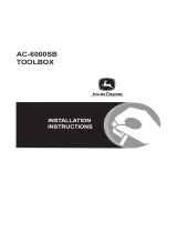
The diagram below shows a DM-RMC-100-C in a standalone application. In this
application, the DM-RMC-100-C is used with a DM 8G+ transmitter such as the
DM-TX-201-C and is not used with a DM switcher.
DM-RMC-100-C in a Standalone Application

Crestron DM-RMC-100-C DigitalMedia 8G+ Receiver 100
Operations & Installation Guide – DOC. 7000C DigitalMedia 8G+ Receiver 100: DM-RMC-100-C 5
Specifications
Specifications for the DM-RMC-100-C are listed in the following table.
DM-RMC-100-C Specifications
SPECIFICATION DETAILS
Video
Input Signal Type
DM 8G+ (DigitalMedia over one CAT5e
twisted pair copper wire), HDBaseT
1
Output Signal Types HDMI, DVI
2
Formats
HDMI with Deep Color and 3D, DVI,
HDCP content protection support
Input Resolutions
Progressive
640 x 480 @ 60 Hz
720 x 480 @ 60 Hz (480p)
720 x 576 @ 50 Hz (576p)
800 x 600 @ 60 Hz
848 x 480 @ 60 Hz
852 x 480 @ 60 Hz
854 x 480 @ 60 Hz
1024 x 768 @ 60 Hz
1024 x 852 @ 60 Hz
1024 x 1024 @ 60 Hz
1280 x 720 @ 50 Hz (720p50)
1280 x 720 @ 60 Hz (720p60)
1280 x 768 @ 60 Hz
1280 x 800 @ 60 Hz
1280 x 960 @ 60 Hz
1280 x 1024 @ 60 Hz
1360 x 768 @ 60 Hz
1365 x 1024 @ 60 Hz
1366 x 768 @ 60 Hz
1400 x 1050 @ 60 Hz
1440 x 900 @ 60 Hz
1600 x 900 @ 60 Hz
1600 x 1200 @ 60 Hz
1680 x 1050 @ 60 Hz
1920 x 1080 @ 24 Hz (1080p24)
1920 x 1080 @ 25 Hz (1080p25)
1920 x 1080 @ 50 Hz (1080p50)
1920 x 1080 @ 60 Hz (1080p60)
1920 x 1200 @ 60 Hz
2048 x 1080 @ 24 Hz
2048 x 1152 @ 60 Hz
plus any other resolution allowed by
HDMI up to 165 MHz pixel clock
(Continued on following page)

DigitalMedia 8G+ Receiver 100 Crestron DM-RMC-100-C
6 DigitalMedia 8G+ Receiver 100: DM-RMC-100-C Operations & Installation Guide – DOC. 7000C
DM-RMC-100-C Specifications (Continued)
SPECIFICATION DETAILS
Video
Input Resolutions (Continued)
Interlaced
720 x 480 @ 30 Hz (480i)
720 x 576 @ 25 Hz (576i)
1920 x 1080 @ 25 Hz (1080i25)
1920 x 1080 @ 30 Hz (1080i30)
plus any other resolution allowed by
HDMI up to 165 MHz pixel clock
Output Resolutions Matched to input
Audio
Input Signal Type DM 8G+, HDBaseT
Output Signal Type HDMI
Formats
Dolby Digital
®
,
Dolby Digital EX, Dolby
Digital Plus, Dolby TrueHD, DTS
®
,
DTS-ES, DTS 96/24, DTS-HD High Res,
DTS-HD Master Audio, up to 8ch PCM
Communications
DigitalMedia
DM 8G+, HDCP management, EDID
format management, CEC, PoDM,
HDBaseT compliant
Ethernet
10BASE-T/100BASE-TX, auto-switching,
auto-negotiating, auto-discovery, full/half
duplex, DHCP
Power Requirements
3
Power Pack
0.75 amps @ 24 Vdc;
100-240 Vac, 50/60 Hz power pack
included
Power over DM (PoDM)
PoDM PD (Powered Device), capable of
being powered by a PoDM PSE (Power
Sourcing Equipment)
Power over HDBaseT (PoH)
PoH PD, capable of being powered by a
PoH PSE
Minimum 2-Series Control System
Update File
4, 5
Version 4.001.1012 or later
Environmental
Temperature 32º to 104º F (0º to 40º C)
Humidity 10% to 90% RH (non-condensing)
Heat Dissipation 29 Btu/h
Enclosure
Chassis
Metal, black finish, with two integral
mounting flanges, vented top and bottom
Mounting
Freestanding, surface mount, or attach to
a single rack rail
(Continued on following page)

Crestron DM-RMC-100-C DigitalMedia 8G+ Receiver 100
Operations & Installation Guide – DOC. 7000C DigitalMedia 8G+ Receiver 100: DM-RMC-100-C 7
DM-RMC-100-C Specifications (Continued)
SPECIFICATION DETAILS
Dimensions
Height 6.09 in (155 mm)
Width 5.63 in (143 mm)
Depth 1.02 in (26 mm)
Weight 17 oz (468 g)
Included Accessory Universal 24 Vdc power pack
Available Accessories
CBL-HD Crestron Certified HDMI Interface Cable
CBL-HD-DVI
Crestron Certified HDMI to DVI Interface
Cable
CBL-HD-LOCK Locking High-Speed HDMI Cable
CNSP-XX Custom Serial Interface Cable
DM-8G-CONN-100 DigitalMedia 8G Cable Connectors
DM-8G-CRIMP Crimping Tool for DM-8G-CONN
DM-CBL-8G DigitalMedia 8G Cable
IRP2 IR Emitter Probe
MP-WP140
Media Presentation Wall Plate – DVI with
Mini-TRS Stereo Audio
MP-WP152 Media Presentation Wall Plate – HDMI
MP-WP181-C
Media Presentation Wall Plate –
DigitalMedia 8G+
MPI-WP150
Media Presentation Wall Plate –
International Version – HDMI
MPI-WP181-C
Media Presentation Wall Plate –
International Version – DigitalMedia 8G+
1. For DM 8G+ wiring, use Crestron DM-CBL-8G DigitalMedia 8G cable, Crestron DM-CBL
DigitalMedia cable, Crestron DM-CBL-D DigitalMedia D cable, or generic CAT5e (or better) UTP or
STP. Maximum wire length for DM 8G+ is 330 feet (100 meters) between devices. Shielded cable
and connectors are recommended to safeguard against unpredictable environmental electrical noise
which may impact performance at resolutions above 1080p. Refer to the latest version of the Crestron
DigitalMedia Design Guide (Doc. 4546) for complete system design guidelines. DM 8G+ is also
compatible with HDBaseT Alliance specifications for connecting to HDBaseT compliant equipment.
All wire and cables sold separately.
2. HDMI requires an appropriate adapter or interface cable to accommodate a DVI signal. CBL-HD-DVI
interface cable sold separately.
3. A power pack, power over DM, or power over HDBaseT can be used to power the DM-RMC-100-C.
4. The latest software versions can be obtained from the Crestron Web site. Refer to the NOTE
following these footnotes.
5. Crestron 2-Series control systems include the AV2 and PRO2. Consult the latest Crestron Product
Catalog for a complete list of 2-Series control systems.
NOTE: Crestron software and any files on the Web site are for authorized Crestron
dealers and Crestron Authorized Independent Programmers (CAIP) only. New users
may be required to register to obtain access to certain areas of the site (including the
FTP site).

DigitalMedia 8G+ Receiver 100 Crestron DM-RMC-100-C
8 DigitalMedia 8G+ Receiver 100: DM-RMC-100-C Operations & Installation Guide – DOC. 7000C
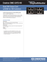
Physical Description
This section provides information on the connections, controls and indicators
available on the DM-RMC-100-C.
DM-RMC-100-C Physical View (Front View)
DM-RMC-100-C Physical Views (Left and Right Side Views)

Crestron DM-RMC-100-C DigitalMedia 8G+ Receiver 100
Operations & Installation Guide – DOC. 7000C DigitalMedia 8G+ Receiver 100: DM-RMC-100-C 9
DM-RMC-100-C Overall Dimensions (Front View)
5.55 in
(141 mm)
5.45 in
(139 mm)
4.63 in
(118 mm)
DM-RMC-100-C Overall Dimensions (Bottom View)
5.63 in
(143 mm)
1.00 in
(25 mm)
1.02 in
(26 mm)

DigitalMedia 8G+ Receiver 100 Crestron DM-RMC-100-C
10 DigitalMedia 8G+ Receiver 100: DM-RMC-100-C Operations & Installation Guide – DOC. 7000C
DM-RMC-100-C Overall Dimensions (Left and Right Side Views)
4.97 in
(127 mm)
6.09 in
(155 mm)
2
3
4
5
7
9
10
8
6
11
1
Connectors, Controls & Indicators
#
CONNECTORS
1
,
CONTROLS &
INDICATORS
DESCRIPTION
1 HDMI OUT LED
(1) Green LED, indicates video signal
presence at the HDMI output
2
HDMI OUT
(1) 19-pin Type A HDMI female;
HDMI digital video/audio output;
Supports DVI
2
3
COM
(1) 5-pin 3.5 mm detachable terminal
block, bidirectional RS-232 port;
Up to 115.2k baud, hardware and
software handshaking support
4
IR (1-2)
(1) 4-pin 3.5 mm detachable terminal
block comprising two IR/serial ports;
IR output up to 1.1 MHz;
1-way serial TTL/RS-232 (0-5 volts)
up to 19200 baud
3
(Continued on following page)

Crestron DM-RMC-100-C DigitalMedia 8G+ Receiver 100
Operations & Installation Guide – DOC. 7000C DigitalMedia 8G+ Receiver 100: DM-RMC-100-C 11
Connectors, Controls & Indicators
#
CONNECTORS
1
,
CONTROLS &
INDICATORS
DESCRIPTION
5
LAN
Green
LED
Amber
LED
Pin 8
Pin 1
(1) 8-pin RJ-45 female, shielded, with two
LED indicators;
10BASE-T/100BASE-TX Ethernet port;
Green LED indicates Ethernet link status;
Amber LED indicates Ethernet activity
PIN SIGNAL PIN SIGNAL
1 TX + 5 N/C
2 TX - 6 RX -
3 RX + 7 N/C
4 N/C 8 N/C
6
(1) 6-32 screw, chassis ground lug
7
DM IN
4
Green
LED
A
mber
LED
Pin 8
Pin 1
(1) 8-pin RJ-45 female, shielded, with two
LED indicators;
DM 8G+ input, HDBaseT compliant;
PoDM and PoH PD (Powered Device) port
5
;
Connects to the DM 8G+ output of a DM
switcher, transmitter, or other DM device, or
to an HDBaseT device via CAT5e or
Crestron DM-CBL-8G cable
6
;
Green LED indicates DM link status;
Solid amber LED indicates HDCP video;
Blinking amber LED indicates non-HDCP
video
8 RESET
(1) Miniature recessed push button for
hardware reset
9
SETUP
(Button and LED)
(1) Miniature recessed push button for
Ethernet setup and (1) red LED
10
24 V
0.75A MAX
(1) 2.1 x 5.5 mm dc power connector;
24 volt dc power input;
Power pack included
11 Power LED
(1) Green LED, indicates operating power
supplied from local power pack, PoDM, or
PoH
1. Interface connectors for the COM and IR ports are provided with the unit.
2. HDMI requires an appropriate adapter or interface cable to accommodate a DVI signal. CBL-HD-DVI
interface cable sold separately.
3. Maximum string length for serial commands sent via the IR port should be no greater than
40 characters.

DigitalMedia 8G+ Receiver 100 Crestron DM-RMC-100-C
12 DigitalMedia 8G+ Receiver 100: DM-RMC-100-C Operations & Installation Guide – DOC. 7000C
4. The DM IN port consists of one RJ-45 connector. Refer to the following table for the connector
pinouts.
DM IN Connector Pinouts
18
PIN # WIRE COLOR PIN # WIRE COLOR
1 Orange/White 5 Blue/White
2 Orange 6 Green
3 Green/White 7 Brown/White
4 Blue 8 Brown
5. Receiving Power over DM (PoDM) or Power over HDBaseT (PoH) requires connection to a switcher
or other equipment that has a PoDM or PoH PSE (Power Sourcing Equipment) port.
6. For DM 8G+ wiring, use Crestron DM-CBL-8G DigitalMedia 8G cable, Crestron DM-CBL
DigitalMedia cable, Crestron DM-CBL-D DigitalMedia D cable, or generic CAT5e (or better) UTP or
STP. Maximum wire length for DM 8G+ is 330 feet (100 meters) between devices. Shielded cable
and connectors are recommended to safeguard against unpredictable environmental electrical noise
which may impact performance at resolutions above 1080p. Refer to the latest version of the Crestron
DigitalMedia Design Guide (Doc. 4546) for complete system design guidelines. DM 8G+ is also
compatible with HDBaseT Alliance specifications for connecting to HDBaseT compliant equipment.
All wire and cables sold separately.

Crestron DM-RMC-100-C DigitalMedia 8G+ Receiver 100
Operations & Installation Guide – DOC. 7000C DigitalMedia 8G+ Receiver 100: DM-RMC-100-C 13
Setup
Network Wiring
When wiring the DM network, consider the following:
Use Crestron Certified Wire.
Use Crestron power supplies for Crestron equipment.
CAUTION: Failure to use Crestron power supplies could cause equipment
damage or void the Crestron warranty.
Provide sufficient power to the system.
For DM 8G+ wiring, use Crestron DM-CBL-8G DigitalMedia 8G cable,
Crestron DM-CBL DigitalMedia cable, Crestron DM-CBL-D DigitalMedia
D cable, or generic CAT5e (or better) UTP or STP. Maximum wire length
for DM 8G+ is 330 feet (100 meters) between devices. Shielded cable and
connectors are recommended to safeguard against unpredictable
environmental electrical noise which may impact performance at resolutions
above 1080p. Refer to the latest version of the Crestron DigitalMedia
Design Guide (Doc. 4546) for complete system design guidelines. DM 8G+
is also compatible with HDBaseT Alliance specifications for connecting to
HDBaseT compliant equipment.
The DM-RMC-100-C also uses high-speed Ethernet for communications between
the device and a control system, computer, media server, and other IP-based devices.
For general information on connecting Ethernet devices in a Crestron system, refer to
the latest version of the Crestron e-Control
Reference Guide (Doc. 6052), which is
available from the Crestron Web site (www.crestron.com/manuals
). For information
specifically related to Ethernet connectivity using DigitalMedia devices, refer to the
latest version of the Crestron IP Considerations Guide for the IT Professional (Doc.
4579), which is also available from the Crestron Web site
(www.crestron.com/dmresources
).
Identity Code
NOTE: In the SIMPL Windows program, the IP ID of the DM-RMC-100-C is
assigned automatically and does not require additional programming when the
DM-RMC-100-C is dropped onto an output card of a DM switcher. Use the
information below when the DM-RMC-100-C is dropped directly into an Ethernet
slot on the control system in SIMPL Windows without a DM switcher.
The IP ID is set within the DM-RMC-100-C IP table using Crestron Toolbox™.
For information on setting an IP table, refer to the Crestron Toolbox help file.
The IP IDs of multiple DM-RMC-100-C devices in the same system must be unique.
When setting the IP ID, consider the following:
The IP ID of each unit must match an IP ID specified in the SIMPL
Windows program.
Each device using IP to communicate with a control system must have a
unique IP ID.

DigitalMedia 8G+ Receiver 100 Crestron DM-RMC-100-C
14 DigitalMedia 8G+ Receiver 100: DM-RMC-100-C Operations & Installation Guide – DOC. 7000C
Installation
The DM-RMC-100-C mounts on a flat surface such as a wall or ceiling.
The DM-RMC-100-C can also be mounted on a rack rail.
Ventilation
The DM-RMC-100-C should be used in a well-ventilated area. The venting holes
should not be obstructed under any circumstances.
To prevent overheating, do not operate this product in an area that exceeds the
environmental temperature range listed in the table of specifications.
Mounting on a Flat Surface
To mount the DM-RMC-100-C on a flat surface such as a wall or ceiling, use four
mounting screws (not included). The following illustration shows mounting of the
DM-RMC-100-C on a wall.
NOTE: To ensure optimum ventilation when mounted on a wall, position the
DM-RMC-100-C vertically so that the venting holes are positioned at the top and
bottom of the unit.
Mounting DM-RMC-100-C on a Wall
Mounting Screws (4)
(Not Included)
/