Crestron GREEN LIGHT GLPX-HSW-FT User manual
- Category
- Network switches
- Type
- User manual
This manual is also suitable for

GREEN LIGHT
®
EXPRESS Power Switching Cabinet GLPX-HSW-FT
Introduction
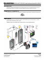
CRESTRON GREEN LIGHT EXPRESS power switching cabinets come pre-configured with GLXP switching
modules already installed. The cabinets only require installation and wiring of feed and load circuits.
Regulatory Compliance
The cabinet and modules are Listed to applicable UL Standar ds and requirements by Underwriters Laboratories Inc.
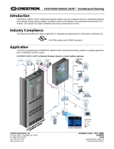
Application
The following diagram shows CRESTRON GREEN LIGHT EXPRESS power switching cabinets in a lighting
application that is controlled by an IPAC system.
CRESTRON GREEN LIGHT EXPRESS Power Switching Cabinets in a Typical Lighting Application
C
R
E
S
N
E
T
O
V
E
R
R
I
D
E
C
R
E
S
N
E
T
C
O
N
T
R
O
L
C
R
E
S
N
E
T
Crestron Electronics, Inc. Installation Guide – DOC. 6888B
15 Volvo Drive Rockleigh, NJ 07647 (2025419)
Tel: 888.CRESTRON 06.10
Fax: 201.767.7576 Specifications subject to
www.crestron.com change without notice.

Power Switching Cabinet GLPX-HSW-FT CRESTRON GREEN LIGHT
®
EXPRESS
Physical Description
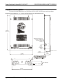
This section shows the dimensions of the CRESTRON GREEN LIGHT EXPRESS power switching cabinets.
Dimensions of GLPX-HSW-FT-8 , -12, -16 Power Switching Cabinets (Front, Side and Bottom View)
24 1/4"
(616 mm)
16 1/8”
(409 mm)
3 1/16”
(78 mm)
KNOCKOUT FOR 3/4”
(20 mm) CONDUIT
(TYPICAL BOTH
SIDES)
4 7/16”
(113 mm)
1/4” (7 mm)
3 1/4”
(83 mm)
2 1/2” (64 mm)
14 3/8"
(365 mm)
1 1/4” (32 mm)
2 • GREEN LIGHT
®
EXPRESS Power Switching Cabinet GLPX-HSW-FT Installation Guide – DOC. 6888B

CRESTRON GREEN LIGHT
®
EXPRESS Power Switching Cabinet GLPX-HSW-FT
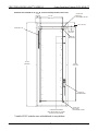
Dimensions of GLPX-HSW-FT-8 , -12, -16 Power Switching Cabinets (Internal View)
23 1/2"
(597 mm)
18 15/16”
(481 mm)
(2X) Ø 7/16 ( 12 )
MOUNTING HOLES
Ømm
(2x) 11/16”
(19 mm)
2 1/8” (55 mm)
(2x) Ø 5/8”
(Ø 16 mm)
(2X) Ø 5/16”
(Ø 8 mm)
(58 mm)
2 1/4”
10 7/8”
MOUNTING HOLES
(276 mm)
* TIE WRAP HOLDERS
(MAY BE MOVED TO OTHER
HOLES AS REQUIRED)
SERVICE
SCREWDRIVER
Installed GLXP modules come with additional tie wrap holders. *
Installation Guide – DOC. 6888B GREEN LIGHT
®
EXPRESS Power Switching Cabinet GLPX-HSW-FT • 3

Power Switching Cabinet GLPX-HSW-FT CRESTRON GREEN LIGHT
®
EXPRESS
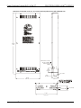
Dimensions of GLPX-HSW-FT-20, -24, -28, -32 Power Switching Cabinets (Front, Side and Bottom View)
16 1/8”
(409 mm)
39 5/8”
(1 m)
3 1/16”
(78 mm)
KNOCKOUT FOR 3/4”
(20 mm) CONDUIT
(TYPICAL BOTH
SIDES)
4 7/16”
(113 mm)
1/4” (7 mm)
3 1/4”
(83 mm)
2 1/2” (64 mm)
14 3/8"
(365 mm)
1 1/4” (32 mm)
4 • GREEN LIGHT
®
EXPRESS Power Switching Cabinet GLPX-HSW-FT Installation Guide – DOC. 6888B

CRESTRON GREEN LIGHT
®
EXPRESS Power Switching Cabinet GLPX-HSW-FT
Dimensions of GLPX-HSW-FT-20, -24, -28, -32 Power Switching Cabinets (Internal View)
2 1/8” (55 mm)
(2X) Ø 5/16”
(Ø 8 mm)
MOUNTING HOLES
(2x) 11/16”
(19 mm)
10 7/8”
(276 mm)
2 1/4”
(58 mm)
GROUND LUG
38 7/8”
(998 mm)
34 3/8”
(873 mm)
(2X) Ø 7/16
(Ø 12 mm)
MOUNTING HOLES
(2x) Ø 5/8”
(Ø 16 mm)
SERVICE
SCREWDRIVER
* TIE WRAP HOLDERS
(MAY BE MOVED TO OTHER
HOLES AS REQUIRED)
Installed GLXP modules come with additional tie wrap holders. *
Installation Guide – DOC. 6888B GREEN LIGHT
®
EXPRESS Power Switching Cabinet GLPX-HSW-FT • 5

Power Switching Cabinet GLPX-HSW-FT CRESTRON GREEN LIGHT
®
EXPRESS
Installation
Observe the following when installing the cabinet:
• The cabinet must be mounted by a licensed electrician in accordance with all national and local codes.
Refer to the diagram below for specific requirements.
• The cabinet is designed for surface mounting on a wall.
• Cabinets are intended for indoor use only.
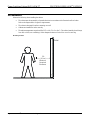
• The ambient temperature range should be 32°F to 104°F (0°C to 40°C). The relative humidity should range
from 10% to 90% (non-condensing). Allow adequate clearance in front of the cover for servicing.
Mounting Location
3 ft
(0.9 m)
Minimum
Required
Clearance
Wall
6 • GREEN LIGHT
®
EXPRESS Power Switching Cabinet GLPX-HSW-FT Installation Guide – DOC. 6888B

CRESTRON GREEN LIGHT
®
EXPRESS Power Switching Cabinet GLPX-HSW-FT
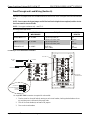
Wiring
NOTE: All wiring must be installed in accordance with all local and national electrical codes.
NOTE: Refer to the torque settings specified on pages 8 and 9.
CRE GLXP low profile switching modules installed.
The follo e cabinet:
• and N input terminals and connect loads to SW output
• Connect control wiring (section B of the following diagram)
STRON GREEN LIGHT EXPRESS cabinets are shipped with
wing must be performed after mounting th
Connect incoming feed conductors to the L
terminals (section A of the following diagram)
FEEDS
A
B
CLASS 2
WIRING ONLY
FROM
BREAKER
PANEL
TO
LOADS
FEEDS
FROM
BREAKER
PANEL
TO
LOADS
SERVICE
SCREWDRIVER
Installation Guide – DOC. 6888B GREEN LIGHT
®
EXPRESS Power Switching Cabinet GLPX-HSW-FT • 7

Power Switching Cabinet GLPX-HSW-FT CRESTRON GREEN LIGHT
®
EXPRESS
Feed-Through and Load Wiring (Section A)
ION: Bypass jumpers are provided on each output to allow testing and to protect the modules during CAUT
installation. The jumper shorts the L and SW terminals so that the load circuit is energized when
is on.
the branch breaker
NOTE: Do not remove the bypass jumper until all feed and load wiring has been completed, and the circuits
have been tested for electrical faults.
NOTE: Use copper conductors only – rated 75°C.
Wire
ORQUE STRIP
LENGTH
Gauge and Torque Values
TERMINAL CONNECTOR MAX
WIRE RANGE
T
L AND N INPUTS 26-10 AWG 5.31 lb-in (0.6 Nm) to
7.08 lb-in (0.8 Nm) max
3/8”
(9 mm)
SW OUTPUTS 26-10 AWG 5.31 lb-in (0.6 Nm) to
7.08 lb-in (0.8 Nm) max
3/8”
(9 mm)
GROUND LUG 14-4 AWG 25-45 lb-in
(2.8-5.1 Nm)
3/4"
(19 mm)
Load Wiring for GLXP-HSW8 and GLXP-HSW12
TO NEUTRAL*
TO BRANCH BREAKER
TO LOAD
JUMPER
L
CIRCUIT BREAKER (20A MAX)
NEUTRAL
BUS
TO LOADS
N
L
GROUND LUG
N1
L1
SW1
SERVICE
SCREWDRIVER
* A single NEUTRAL connection is required for each module.
1. Test the circuit for electrical faults by turning on each circuit breaker, checking that the breakers do not
trip, and that power is delivered to the proper loads.
2. Turn off the circuit breaker(s) and remove all jumpers.
3. Turn on the circuit breakers.
8 • GREEN LIGHT
®
EXPRESS Power Switching Cabinet GLPX-HSW-FT Installation Guide – DOC. 6888B

CRESTRON GREEN LIGHT
®
EXPRESS Power Switching Cabinet GLPX-HSW-FT
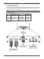
Control Wiring (Section B)
The bottom of the cabinet contains Cresnet connections for interfacing to the rest of the Crestron control system
and a power port to provide an alternate source of 24 volt power to the modules. It also provides an override input
which can be tied to devices such as the GLS-PLS-120/277 phase-loss sensor, or other devices that provide a dry
contact
® ®
,
closure (manual switch, fire alarm relay, etc.).
NOTE: Interface connectors for NET (x2), POWER (x1), and OVERRIDE (x3) ports are provided.
Wire Gauge and Torque Values
TERMINAL CONNECTOR MAX TORQUE STRIP
WIRE RANGE LENGTH
NET -12 AW
43 lb-in
.5 Nm)
26 G
4.
(0
1/4”
(6 mm)
POWER 26-12 AWG
4.43 lb-in
(0.5 Nm)
1/4”
(6 mm)
OVERRIDE 26-12 AWG
4.4
(0.5 Nm)
3 lb-in 1/4”
(6 mm)
Connector Wiring
RED
WHITE
BLUE
BLACK
NET:
TO CONTROL SYSTEM AND
OTHER CRESNET DEVICES
RED
WHITE
BLUE
BLACK
POWER:
PROVIDES CRESNET
LESPOWER TO THE MODU
OVERRIDE:
FROM OTHER CABINET;
FROM ALARM, ETC.
(OPTIONAL); TO OTHER
CABINET(S) IF NECESSARY
MODULES:
TO GLXP MODULES
(PREWIRED)
Installation Guide – DOC. 6888B GREEN LIGHT
®
EXPRESS Power Switching Cabinet GLPX-HSW-FT • 9

Power Switching Cabinet GLPX-HSW-FT CRESTRON GREEN LIGHT
®
EXPRESS
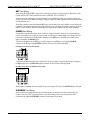
NET Port Wiring
When wiring the supplied NET connectors for connection to a Crestron control system or other device on the
Cresnet network, use Crestron certified wire such as CRESNET-NP or CRESNET-P.
To ensure optimum performance over the full range of your installation topology, use Crestron certified wire.
Failure to do so may incur additional charges if support is required to identify performance deficiencies because
When daisy-chaining connections between NET ports, strip the ends of the wires carefully to avoid nicking the
the ends of the wires that share a pin on the network connector, insert the connection
s e retai epeat the procedure for the other three conductors.
WER Port Wiring
odule in the cabinet receives power via the line voltage connected to channel 1. In the event that line
is un module can recei a a backup ge supply. Low voltage (24 VDC)
ay be suppl he modules eithe a the NE externally via a Cresnet power
WER port.
To power the modules from the NET port, in per from th n on the supplied POWER
he EXT pin on the POWER connector as shown in the following diagram.
Providing Cresnet Power Via The Net Port
of using improper wire.
conductors. Twist together
into the Cre net connector, tighten th ning screw. R
PO
Each m
voltage
power m
available, the
ied to t
ve power vi
r internally vi
low volta
T port or
supply connected to the PO
stall a jum e INT pi
connector to t
To power the modules externally from a Cresnet 24 VDC power supply, connect the external power supply to
the EXT and G pins on the POWER supplied connector as shown in the following diagram.
Providing Cresnet Power Via Dedicated Power Supply
CRESTRON 24 VDC
POWER SUPPLY
G 24
When properly connected and receiving 24 VDC power, the green LED next to the MODULES port will light.
OVERRIDE Port Wiring
When a connection is applied between the override terminals, the modules will enter override mode. The
Crestron GLS-PLS-120/277 phase-loss sensor or any device that provides a dry contact closure can be
connected to the supplied OVERRIDE connector on the bottom of the cabinet.
10 • GREEN LIGHT
®
EXPRESS Power Switching Cabinet GLPX-HSW-FT Installation Guide – DOC. 6888B

CRESTRON GREEN LIGHT
®
EXPRESS Power Switching Cabinet GLPX-HSW-FT
Testing
Ma
Ligh
To t
and t
rele
NO ram may change the settings if the Override mode is not enabled.
nual Control
ting modules can be manually controlled from the front panel.
oggle the output between off and on, tap the appropriate ON/OFF button. The corresponding LED illuminates
he output state is shown on the NET ID display (“oF” for off, “On” for on) for two seconds after the button is
ased.
TE: The control system prog
Ov
The
valu ttings, refer to “Save Override Settings” below.
To e
NOTE:
erride Mode
Override mode overrides the control system program and sets all of the output states to the stored override
es. For instructions on saving override se
nable Override mode, press and release the OVR button. The OVR LED flashes slowly.
If the Override mode was enabled from an external device (i.e. a contact closure is present on the
OV flash quickly. Pressing the OVR button has no effect. ERRIDE terminals), the OVR LED will
To disable Override mode, press the OVR button again. The OVR LED extinguishes and the outputs return to the
states set by the control system program.
NOTE: If override states have not been stored, the factory default override state is all loads on.
Save Override Settings
The
mod
NO an prevent locally saving the override state. If this setting is
state of each output can be saved as an override setting, which can be automatically recalled when the Override
e is enabled.
TE: The control system program has a setting that c
enabled, the display shows “Er” when trying to save override states. For more information, refer to the SIMPL
Windows help file.
To save the states of all outputs as the override setting, press and hold the OVR button for three seconds until the
LED blinks once. The OVR LED blinks to indicate the new override setting has been stored.
System Operation and Commissioning
This cabinet has been des ponent of a programmed Crestron system. System commissioning by an
authorized Crestron representative
must
igned as a com
be performed to ensure system operation.
Once t
[1-8 ssioning.
he cabinet has been wired and the modules have been tested, contact Crestron at 1-888-CRESTRON
88-273-7876] to schedule commi
Installation Guide – DOC. 6888B GREEN LIGHT
®
EXPRESS Power Switching Cabinet GLPX-HSW-FT • 11

Power Switching Cabinet GLPX-HSW-FT CRESTRON GREEN LIGHT
®
EXPRESS
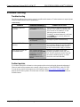
Problem Solving
Troubleshooting
ituations. If further assistance is required, please
TROUBLE
The following table provides corrective action for possible trouble s
contact a Crestron customer service representative.
Troubleshooting
POSSIBLE CAUSE(S) CORRECTIVE ACTION
Power not delivered to
the module.
If the module is powered internally, verify
that the circuit breaker connected to the
first channel on the module is on and
at
delivering power to the module.
If module is powered externally, verify th
the POWER port is correctly wired and
receiving power.
Module(s) does not
function.
System commissioning
not complete.
Arrange for system commissioning.
Module’s LED is AC power not present on PWR
flashing. L1.
Check that the branch breaker feeding L1
to function, but will draw power from the
has not tripped. Note that unit will continue
backup Cresnet power supply if available.
Unit cannot be taken out Short (contact closure)
of Override mode
exists between G and OVR
terminals on any of the
OVERRIDE terminals
present at bottom of the
cabinet.
Determine the reason for the short.
Remove or remedy the short (e.g. GLS-
PLS-120/277 phase-loss sensor may not
phase-loss has been detected).
have been installed properly, or actual
Further Inquiries
888-273-7876].
You can also log onto the online help section of the Crestron website (
www.crestron.com/onlinehelp
If you cannot locate specific information or have questions after reviewing this guide, please take advantage of
Crestron's award winning customer service team by calling Crestron at 1-888-CRESTRON [1-
) to ask
user account to fully benefit from all questions about Crestron products. First-time users will need to establish a
available features.
12 • GREEN LIGHT
®
EXPRESS Power Switching Cabinet GLPX-HSW-FT Installation Guide – DOC. 6888B

CRESTRON GREEN LIGHT
®
EXPRESS Power Switching Cabinet GLPX-HSW-FT
Appendix A: Setting Module Net IDs
The following procedure will normally be performed by an authorized Crestron representative as part of the System
system wiring and basic testing as described on pages 7 and 11, it is not necessary to
ch module in the cabinet can be changed from the front panel of each module. The Net IDs of each
module in ust be uniqu
To e front p
the recessed SETU r the Setup mode.
2. As shown in the following diagram, press the left button u he left digit
of the Net ID or press the right button under the NET ID d
number.
Changing the Net ID
Commissioning phase. For
perform this step. Only perform this step if instructed by an authorized Crestron representative, or when replacing
modules on a system that have already been commissioned (in the latter case the Net ID should be set to match the
Net ID of the module being replaced).
The Net ID of ea
the system m e.
set the Net ID using th
1. Press
anel:
P button to ente The SETUP LED illuminates.
nder the NET ID display to change t
isplay to change the right digit of the Net ID
CHANGES
LEFT DIGIT
CHANGES
RIGHT DIGIT
LABEL FOR
NET ID
SETUP
BUTTON & LED
RIGHT DIGITLEFT DIGIT
et ID is displayed, press the SETUP button to exit the Setup mode. The SETUP LED 3. When the desired N
extinguishes.
If the SETUP button is not pressed, the Setup mode will time out after one minute of inactivity and the Net
ID will revert back to its original value.
Installation Guide – DOC. 6888B GREEN LIGHT
®
EXPRESS Power Switching Cabinet GLPX-HSW-FT • 13

Power Switching Cabinet GLPX-HSW-FT CRESTRON GREEN LIGHT
®
EXPRESS
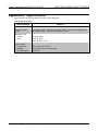
Appendix B: Specifications
Specifications for the GLXP modules are listed in the following table.
GLXP Module Specifications
SPECIFICATION DETAILS
Input Voltage 100 – 277 VAC 50/60 Hz
Supported Load
Types
Incandescent, HID, magnetic low voltage (MLV), electronic low voltage (ELV),
neon/cold cathode, and fluorescent ballasts, motor
Maximum Load
Lighting 16 A per output
tMo or
½ HP @ 120V
1 HP @ 230V / 277V
Environmental
Temperature
32º to 104º F (0º to 40º C)
Humidity 10% to 90% RH (non-condensing)
Heat Dissipation 10 BTU/Hr
14 • GREEN LIGHT
®
EXPRESS Power Switching Cabinet GLPX-HSW-FT Installation Guide – DOC. 6888B

CRESTRON GREEN LIGHT
®
EXPRESS Power Switching Cabinet GLPX-HSW-FT
This page is intentionally left blank.
Installation Guide – DOC. 6888B GREEN LIGHT
®
EXPRESS Power Switching Cabinet GLPX-HSW-FT • 15

Power Switching Cabinet GLPX-HSW-FT CRESTRON GREEN LIGHT
®
EXPRESS
Return and Warranty Policies
Merchandise Returns / Repair Service
1. No merchandise may be returned for credit, exchange or service without prior authorization from
CRESTRON. To obtain warranty service for CRESTRON products, contact an authorized
CRESTRON dealer. Only authorized CRESTRON dealers may contact the factory and request an
RMA (Return Merchandise Authorization) number. Enclose a note specifying the nature of the
problem, name and phone number of contact person, RMA number and return address.
2. Products may be returned for credit, exchange or service with a CRESTRON Return Merchandise
Authorization (RMA) number. Authorized returns must be shipped freight prepaid to
CRESTRON, 6 Volvo Drive, Rockleigh, N.J. or its authorized subsidiaries, with RMA number
clearly marked on the outside of all cartons. Shipments arriving freight collect or without an RMA
number shall be subject to refusal. CRESTRON reserves the right in its sole and absolute
discretion to charge a 15% restocking fee plus shipping costs on any products returned with an
RMA.
3. Return freight charges following repair of items under warranty shall be paid by CRESTRON,
shipping by standard ground carrier. In the event repairs are found to be non-warranty, return
freight costs shall be paid by the purchaser.
CRESTRON Limited Warranty
CRESTRON ELECTRONICS, Inc. warrants its products to be free from manufacturing defects in materials and
workmanship under normal use for a period of three (3) years from the date of purchase from CRESTRON,
with the following exceptio ing mechanical parts, pan/tilt heads and
power supplies are covered lay and overlay components are
covered for 90 days; batteries and incandescent lamps are not covered.
This warranty extends to products purchased directly from CRESTRON or an authorized CRESTRON dealer.
Purchasers should inquire of the dealer regarding the nature and extent of the dealer's warranty, if any.
CRESTRON shall not be liable to honor the terms of this warranty if the product has been used in any
application other than that for which it was intended or if it has been subjected to misuse, accidental damage,
modification or improper installation procedures. Furthermore, this warranty does not cover any product that
has had the serial number altered, defaced or removed.
This warranty shall be the sole and exclusive remedy to the original purchaser. In no event shall CRESTRON
be liable for incidental or consequential damages of any kind (property or economic damages inclusive) arising
from the sale or use of this equipment. CRESTRON is not liable for any claim made by a third party or made by
the purchaser for a third party.
CRESTRON shall, at its option, repair or replace any product found defective, without charge for parts or labor.
Repaired or replaced equipment and parts supplied under this warranty shall be covered only by the unexpired
portion of the warranty.
Except as expressly set forth in this warranty, CRESTRON makes no other warranties, expressed or implied,
nor authorizes any other party to offer any warranty, including any implied warranties of merchantability or
fitness for a particular purpose. Any implied warranties that may be imposed by law are limited to the terms of
this limited warranty. This warranty statement supersedes all previous warranties.
Trademark Information
All brand names, product names and trademarks are the sole property of their respective owners. Windows is a registered trademark of
Microsoft Corporation. Windows95/98/Me/XP/Vista/7 and WindowsNT/2000 are trademarks of Microsoft Corporation.
ns: disk drives and any other moving or rotat
for a period of one (1) year; touchscreen disp
16 • GREEN LIGHT
®
EXPRESS Power Switching Cabinet GLPX-HSW-FT Installation Guide – DOC. 6888B
-
 1
1
-
 2
2
-
 3
3
-
 4
4
-
 5
5
-
 6
6
-
 7
7
-
 8
8
-
 9
9
-
 10
10
-
 11
11
-
 12
12
-
 13
13
-
 14
14
-
 15
15
-
 16
16


Crestron GREEN LIGHT GLPX-HSW-FT User manual
- Category
- Network switches
- Type
- User manual
- This manual is also suitable for
Ask a question and I''ll find the answer in the document
Finding information in a document is now easier with AI
Related papers
-
Crestron CNLDM-6-277 User manual
-
-
-
-
-
-
-
-
-
Other documents
-
AMX RDM-HSW Product information
-
 Crestron electronic 120 Volt User manual
-
 Crestron electronic CNLDAB-4A User manual
-
Tork ELC74 Installation guide
-
 Crestron electronic CNLFDB-4 User manual
-
 Crestron electronic DIN-8SW8 User manual
-
 Crestron electronic DIN-1DIMU4 User manual
-
 Crestron electronic Residential Lighting User manual
-
 Calculated Industries 6260 User manual
-
 Crestron electronic CLS-C6RF User manual


