Page is loading ...

GLEX - Automation Enclosures
Crestron Electronics, Inc. Installation Guide – DOC. 7292A
15 Volvo Drive Rockleigh, NJ 07647 (2032413)
Tel: 888.CRESTRON 02.12
Fax: 201.767.7576 Specifications subject to
www.crestron.com change without notice.
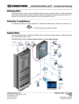
Introduction
Crestron
®
GLEX-FT-24/56/84-IPAC Green Light
Express
®
enclosures are wall-mounted metal enclosures
that house Crestron switching modules (GLPX-SW
series), high-inrush switching modules (GLPX-HSW
series) and heavy duty switching modules
(GLPX-HDSW) (all sold separately). The
GLEX-FT-24/56/84-IPAC includes a Crestron IPAC
(Integrated Automation Computer for Green Light Power
Switching) integrated into the cover of the enclosure. The
GLEX-Series enclosures are available in a variety of
sizes. Refer to the illustration and table on this page for an
alphanumeric listing of GLEX-Series models, overall
dimensions, and weight.
NOTE: Two keyholes are located within the enclosure
and should be used if surface mounting.
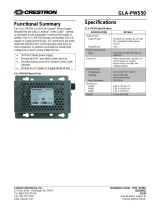
Functional Summary
Regulatory Compliance
This product is Listed to applicable UL Standards and
requirements by Underwriters Laboratories Inc.
Specifications
DIMENSIONS
1
GLEX-FT-24-IPAC GLEX-FT-56-IPAC GLEX-FT-84-IPAC
Cover Thickness
1/16
(1)
1/16
(1)
1/16
(1)
Weight (empty)
2
24
(10.9)
34
(15.4)
44
(20.0)
Maximum Weight (filled)
33
(15.0)
50
(22.7)
74
(33.6)
1. Length is specified in inches and millimeters (in parentheses). Weight is specified in pounds and kilograms (in parentheses).
2. Weight (empty) is the weight of an empty enclosure with cover.
GLEX-FT-24/56/84-IPAC Overall Dimensions (Bottom View)
• 120 or 277 volt dimming and switching
• 8 to 56 circuits per cabinet
• Feed-thru type panels
• Field-replaceable lighting modules
• System design by Crestron
• Factory assembled and tested
• UL924 listed (emergency power equipment)

Automation Enclosures Crestron GLEX
2 • Green Light Express
®
Power Switching Cabinet: GLEX-FT/24/56/84-IPAC Installation Guide – DOC. 7292A
GLEX-FT-24-IPAC Overall Dimensions (Front and Side View)

Crestron GLEX Automation Enclosures
Installation Guide – DOC. 7292A Green Light Express
®
Power Switching Cabinet: GLEX-FT/24/56/84-IPAC • 3
GLEX-FT-56-IPAC Overall Dimensions (Front and Side View)

Automation Enclosures Crestron GLEX
4 • Green Light Express
®
Power Switching Cabinet: GLEX-FT/24/56/84-IPAC Installation Guide – DOC. 7292A
GLEX-FT-84-IPAC Overall Dimensions (Front and Side View)

Crestron GLEX Automation Enclosures
Installation Guide – DOC. 7292A Green Light Express
®
Power Switching Cabinet: GLEX-FT/24/56/84-IPAC • 5
Installation
The enclosure must be mounted by a licensed electrician
in accordance with all national and local codes. Refer to
table on first page for the weight of a fully loaded
enclosure.
When choosing components to place in the enclosure,
refer to the table on page 1 to ensure that the maximum
weight capacity is not exceeded. Each module’s product
page on the Crestron Web site lists the module’s weight.
Modules must be mounted using the column of screw
holes shown in the “Mounting Detail” diagrams.
CAUTION: These enclosures house equipment that
needs to be air-cooled. Therefore, mount in a well-
ventilated area. The ambient temperature range should be
32°F to 104°F (0°C to 40°C). The relative humidity
should range from 0% to 90% (non-condensing).
Furthermore, allow adequate clearance in front of the
vented cover for servicing and ventilation.
NOTE: Unless otherwise indicated, the lighting system
specified in this guide is modular, requiring assembly in
the field by a licensed electrician, in accordance with all
national and local codes.
If you require a UL Listed panel, Crestron offers this
service through its UL Listed panel shop. This includes
complete in factory system configuration and assembly by
Crestron for an additional fee.
NOTE: Install modules into the lowest available spaces
and continue toward the top of the enclosure.
NOTE: Enclosures are intended for indoor use only.
NOTE: When flush mounting, 5/8” drywall is preferred.
Wiring
CAUTION: All power feeds must be protected by 15 or
20 amp circuit breakers (supplied by others).
NOTE: Use copper conductors only – rated 60°C
NOTE: All wiring must be installed in accordance with
all local and national electrical codes.
NOTE: Two snap bushings are supplied. If required,
insert into knockouts at the bottom of the enclosure to
prevent damage to low voltage wiring.
Class 1 and Class 2 field wires must be kept separate.
Refer to the following illustration showing wiring details.
Areas for high voltage (Class 1) wiring are shown along
the sides of the unit. The top and bottom area is reserved
for low voltage (Class 2) wiring.
Tighten all terminal block screws and grounding terminal
block screws to the torque specified in the following
“Torque Data” table.
CAUTION: Failure to properly tighten the screws may
result in poor electrical connection and overheating of the
terminals.
Torque Data
GLPX
Modules
Grounding Terminal
Blocks
Wire Range
22 - 10
14 - 10
8
6 - 4
Torque (In-Lbs)
9
35
40
45
Mounting Details

Automation Enclosures Crestron GLEX
6 • Green Light Express
®
Power Switching Cabinet: GLEX-FT/24/56/84-IPAC Installation Guide – DOC. 7292A
Wiring Details

Crestron GLEX Automation Enclosures
Installation Guide – DOC. 7292A Green Light Express
®
Power Switching Cabinet: GLEX-FT/24/56/84-IPAC • 7
Further Inquiries
If you cannot locate specific information or have
questions after reviewing this guide, please take
advantage of Crestron's award winning customer service
team by calling Crestron at 1-888-CRESTRON
[1-888-273-7876]. For assistance in your region, please
refer to the Crestron Web site (
www.crestron.com/offices)
for a listing of Crestron worldwide offices.
You can also log onto the online help section of the
Crestron Web site (
www.crestron.com/onlinehelp) to ask
questions about Crestron products. First-time users must
establish a user account to fully benefit from all available
features.
Future Updates
As Crestron improves functions, adds new features and
extends the capabilities of the GLEX-FT-24/56/84-IPAC,
additional information may be made available as manual
updates. These updates are solely electronic and serve as
intermediary supplements prior to the release of a
complete technical documentation revision.
Check the Crestron Web site periodically for manual
update availability and its relevance. Updates are
identified as an “Addendum” in the Download column.
The specific patents that cover Crestron products are listed at
patents.crestron.com.
Crestron, the Crestron logo, and Green Light Express are either
trademarks or registered trademarks of Crestron Electronics, Inc. in the
United States and/or other countries. UL and the UL logo are either
trademarks or registered trademarks of Underwriters Laboratories, Inc.
in the United States and/or other countries. Other trademarks and trade
names may be used in this document to refer to either the entities
claiming the marks and names or their products. Crestron disclaims any
proprietary interest in the marks and names of others.
©2012 Crestron Electronics, Inc.
Return and Warranty Policies
Merchandise Returns / Repair Service
1. No merchandise may be returned for credit, exchange or service
without prior authorization from Crestron. To obtain warranty
service for Crestron products, contact an authorized Crestron
dealer. Only authorized Crestron dealers may contact the factory
and request an RMA (Return Merchandise Authorization)
number. Enclose a note specifying the nature of the problem,
name and phone number of contact person, RMA number and
return address.
2. Products may be returned for credit, exchange or service with a
Crestron Return Merchandise Authorization (RMA) number.
Authorized returns must be shipped freight prepaid to Crestron, 6
Volvo Drive, Rockleigh, N.J. or its authorized subsidiaries, with
RMA number clearly marked on the outside of all cartons.
Shipments arriving freight collect or without an RMA number
shall be subject to refusal. Crestron reserves the right in its sole
and absolute discretion to charge a 15% restocking fee plus
shipping costs on any products returned with an RMA.
3. Return freight charges following repair of items under warranty
shall be paid by Crestron, shipping by standard ground carrier. In
the event repairs are found to be non-warranty, return freight
costs shall be paid by the purchaser.
Crestron Limited Warranty
Crestron Electronics, Inc. warrants its products to be free from
manufacturing defects in materials and workmanship under normal use
for a period of three (3) years from the date of purchase from Crestron,
with the following exceptions: disk drives and any other moving or
rotating mechanical parts, pan/tilt heads and power supplies are covered
for a period of one (1) year; touch screen display and overlay
components are covered for 90 days; batteries and incandescent lamps
are not covered.
This warranty extends to products purchased directly from Crestron or
an authorized Crestron dealer. Purchasers should inquire of the dealer
regarding the nature and extent of the dealer's warranty, if any.
Crestron shall not be liable to honor the terms of this warranty if the
product has been used in any application other than that for which it was
intended or if it has been subjected to misuse, accidental damage,
modification or improper installation procedures. Furthermore, this
warranty does not cover any product that has had the serial number
altered, defaced or removed.
This warranty shall be the sole and exclusive remedy to the original
purchaser. In no event shall Crestron be liable for incidental or
consequential damages of any kind (property or economic damages
inclusive) arising from the sale or use of this equipment. Crestron is not
liable for any claim made by a third party or made by the purchaser for a
third party.
Crestron shall, at its option, repair or replace any product found
defective, without charge for parts or labor. Repaired or replaced
equipment and parts supplied under this warranty shall be covered only
by the unexpired portion of the warranty.
Except as expressly set forth in this warranty, Crestron makes no other
warranties, expressed or implied, nor authorizes any other party to offer
any warranty, including any implied warranties of merchantability or
fitness for a particular purpose. Any implied warranties that may be
imposed by law are limited to the terms of this limited warranty. This
warranty statement supersedes all previous warranties.
Crestron software, including without limitation, product development software and product operating system software is licensed to Crestron dealers
and Crestron Authorized Independent Programmers (CAIPs) under a limited non-exclusive, non-transferable license pursuant to separate end-user
license agreement. The terms of this end user license agreement can be found on the Crestron Web site at
www.crestron.com/legal/software_license_agreement.

Automation Enclosures Crestron GLEX
8 • Green Light Express
®
Power Switching Cabinet: GLEX-FT/24/56/84-IPAC Installation Guide – DOC. 7292A
This page is intentionally left blank.
/