Page is loading ...

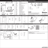
Motherboard Components/ 主板组件
No. Code Descripon
1 SW_ID ID switch buon w/LED
2 QSFP_3 QSFP LAN port #3 (le)
QSFP_2 QSFP LAN port #2 (middle)
QSFP_1 QSFP LAN port #1 (right)
3 SFP+_0_3 SFP+ connectors #0~#3
4 USB3_MLAN BMC Management LAN port (top) / USB 3.0 ports (boom)
5 COM1_VGA Serial port (top)/VGA port(boom)
6 PMBUS PMBus connector
7 ATX1 24 pin power cponnector
8 F_USB3 USB 3.0 header
9 P12V_AUX2 8 pin power connector (for secondary CPU)
10 P12V_AUX1 8 pin power connector (for primary CPU)
11 MINI_CN0 Mini-SAS connector#0 supports SATA3 6Gb/s
12 MINI_CN1 Mini-SAS connector#1 supports SATA3 6Gb/s
13 BAT Baery socket
14 DIMM_P0_B0 Channel 2 slot 0 (for primary CPU)
15 DIMM_P0_B1 Channel 2 slot 1 (for primary CPU)
16 DIMM_P0_D0 Channel 4 slot 0 (for primary CPU)
17 DIMM_P0_D1 Channel 4 slot 1 (for primary CPU)
18 CPU0 Cavium ThunderX CN88xx ARMv8 SoC processor (Primary CPU)
19 DIMM_P0_C1 Channel 3 slot 1 (for primary CPU)
20 DIMM_P0_C0 Channel 3 slot 0 (for primary CPU)
21 DIMM_P0_A1 Channel 1 slot 1 (for primary CPU)
22 DIMM_P0_A0 Channel 1 slot 0 (for primary CPU)
23 DIMM_P1_F0 Channel 2 slot 0 (for secondary CPU)
24 DIMM_P1_F1 Channel 2 slot 1 (for secondary CPU)
25 DIMM_P1_H0 Channel 4 slot 0 (for secondary CPU)
26 DIMM_P1_H1 Channel 4 slot 1 (for secondary CPU)
27 CPU1 Cavium ThunderX CN88xx ARMv8 SoC processor (Secondary CPU)
28 DIMM_P1_G1 Channel 3 slot 1 (for secondary CPU)
29 DIMM_P1_G0 Channel 3 slot 0 (for secondary CPU)
30 DIMM_P1_E1 Channel 1 slot 1 (for secondary CPU)
31 DIMM_P1_E0 Channel 1 slot 0 (for secondary CPU)
32 BP_1 HDD back plane board header
33 FP_1 Front panel header
34 MINI_CN4 Mini-SAS connector#4 supports SATA3 6Gb/s
35 MINI_CN5 Mini-SAS connector#5 supports SATA3 6Gb/s
36 MINI_CN6 Mini-SAS connector#6 supports SATA3 6Gb/s
37 MINI_CN7 Mini-SAS connector#7 supports SATA3 6Gb/s
No. Code Descripon
38 S3_MASK S3 Power On Select Jumper
1-2 Close: Stop an inial power on when BMC
is not ready.
2-3 Close: Keep inial power on.
(Default seng)
39 BIOS_PWD Clearing Supervisor Password jumper
1-2 Close: Normal operaon. (Default seng)
2-3 Close: Skip supervisor password.
40 BIOS_RCVR BIOS recovery jumper
1-2 Close: Normal operaon. (Default seng)
2-3 Close: BIOS recovery mode.
41 COM2 Serial port cable connector
42 LAN Acve LEDs LAN Acve LEDs
LAN3_ACT LAN3 acve LED (upper-le corner)
LAN4_ACT LAN4 acve LED (boom-le corner)
LAN5_ACT LAN5 acve LED (upper-right corner)
LAN6_ACT LAN6 acve LED (boom-right corner)
LAN7_ACT LAN7 acve LED (boom-right corner)
43 CLR_CMOS Clear CMOS jumper
1-2 Close: Normal operaon (Default seng)
2-3 Close: Clear CMOS data.
44 IPMB IPMB connector
45 BUZZER Buzzer
46 PCIE_5 PCI Express x8 slot
47 PCIE_4 PCI Express x8 slot
48 PCIE_3 PCI Express x8 slot
49 MINI_CN3 Mini-SAS connector#3 supports SATA3 6Gb/s
50 MINI_CN2 Mini-SAS connector#2 supports SATA3 6Gb/s
51 PCIE_2 PCI Express x16 slot
52 LED_BMC BMC firmware readiness LED
1 2 3 4
7
5
6
8
9
10
11
12
13
14
15
16
17
19
20
21
22
23
24
25
26
28
29
30
31
32
33
38 42
37
36
35
34
39
40
41 43 44 45
52
46 47 48
49
50
51
1827
CAUTION!
Before you remove or install the system cover:
Make sure the system is not turned on or connected to AC power.
R150-T60 R150-T61
注意!
在卸下或安装系统机盖之前,请注意下列事项:
确保系统未开启且未连接到交流电源。
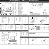
System Components/ 系统组件
CAUTION!
To connect system fan connector, follow the instrucon:
Blue/Red cable connect to odd numbered connector.
White/Amber cable connect to even numbered connector.
注意!
蓝/红电缆连连接于单数风扇插座。
白/橘电缆连连接于双数风扇插座。
1
2
3
4
5
6
7
7
8
10
9
8
8
No Descripon
1 2.5” HDD bays
2 System fan #5/#6 (FAN5/FAN6)
3 System fan #7/#8 (FAN7/FAN8)
4 System fan #9/#10 (FAN9/FAN10)
5 System fan #11/#12 (FAN11/FAN12)
6 System fan #13/#14 (FAN13/FAN14)
7 CPU and CPU heat sink
8 Memory slots
9 PCIe riser bracket
10 Power supply cage
No Descripon
1 3.5” HDD bays
2 System fan #5/#6 (FAN5/FAN6)
3 System fan #7/#8 (FAN7/FAN8)
4 System fan #9/#10 (FAN9/FAN10)
5 System fan #11/#12 (FAN11/FAN12)
6 System fan #13/#14 (FAN13/FAN14)
7 CPU and CPU heat sink
8 Memory slots
9 PCIe riser bracket
10 Power supply cage
1
2
3
4
5
67
7
8
8
8
10
9
Front Panel Header/ 前面板接头
1
24 23
2
HDD Back Plane Board Header/ 硬盘驱动器底板接头
1 2
25 26
No. Pin Define
1 BP_SGP_CLK
3 BP_SGP_LD
5 BP_SGP_DOUT
7 Key Pin
9 GND
11 BP_LED_G_N
13 BP_SGP_DIN
15 GND
17 GND
19 P_3V3_AUX
21 P_3V3_AUX
23 GND
25 BP_PRESENSE
No. Pin Define
2 No Connect
4 FAN_Gate
6 GND
8 Reset
10 BP_LED_A_N
12 GND
14 No Connect
16 SMB_BP_DATA
18 SMB_BP_CLK
20 BMC_ACK
22 BMC_REQ
24 Key Pin
26 GND
No. Pin Define
1 Power LED+
3 No Pin
5 Power LED-
7 HDD LED+
9 HDD LED-
11 Power Buon
13 GND
15 Reset Buon+
17 GND
19 ID Switch+
21 GND
23 NMI Switch-
No. Pin Define
2 5V Standby
4 ID LED+
6 ID LED-
8 System Status LED+
10 System Status LED-
12 LAN1 Acve LED+
14 LAN1 Link LED-
16 SMBus Data
18 SMBus Clock
20 Case Open
22 LAN2 Acve LED+
24 LAN2 Link LED-
R150-T61R150-T60
System Cover/ 机箱盖
1
11
12
2
3
4
5
1
1
1
1
2
2
2
3
4
5
2
3
1
Heat Sink/ 散热装置
System Front View
R150-T60
System Front View
R150-T61
System Rear View
Memory Populaon Configuraon/ 安装内存
DIMM must be populated starng from DIMM_P0_A0/DIMM_P0_B0 socket and must be installed in
matched pairs.
One CPU only supports the populaon of 2/4 (1DPC)/8 (2DPC) in the same me.
System will not boot normally with incorrect populated sequence.
DIMM必须从DDR3_P0_A0//DIMM_P0_B0插槽开始按顺序安装。DIMM必须成对安装。
只能支持一個CPU同時上2/4 (1DPC)/8(2DPC)數量的DIMM。
若安装顺序有误,系统将无法正常开机。
Rank(s) 1 Rank 2 Rank
x8,x16 x8,x16
1 Rank 2 Rank
x8,x16 x8,x16
8 8,16 8 8,16
Data Width
Per DIMM Capacity (GB)
1600MTS
1866MTS
2133MTS
1 DIMM per channel 2 DIMM per channel#DIMM per channel
DDR4 UDIMM Configuration
Rank(s) 1 Rank
x4
8,16
x8
4,8
2 Rank
x4
16,32
x8
8,16
1 Rank
x4
8,16
x8
4,8
2 Rank
x4
16,32
x8
8,16
Data Width
Per DIMM Capacity (GB)
1600MTS
1866MTS
2133MTS
1 DIMM per channel 2 DIMM per channel#DIMM per channel
DDR4 RDIMM Configuration
R150-T61R150-T60
System Fan/ 系统风扇
注意!
确保系统未开机且未连接到交流电源。
断开所有必要的线缆连接。若不遵循这些警告,可能造成人员伤害或设备损坏。
CAUTION!
Before you remove or install the system fan:
Make sure the system is not turned on or connected to the AC power.
Disconnect all necessary cable connecons. Failure to observe these warnings could result in
personal injury or damage to the equipment.
R150-T61
2
3
44
1
R150-T60
1
2
3
4
5
6
7
9
10
11 12
13 14 15 16 17 18 19 20 21 22 23 24 25 26 27 28
8
29
30
31
5
1
234
6 7 8 9
10
11 12 13 14 15 16 17 18 19 20 21 22
R150-T60 HDD Backplane Board Components
R150-T61 HDD Backplane Board Components
Hard Disk Drive and Back Plane Board/ 硬盘驱动器与硬盘驱动器底板
2
1
3
4
4
No Descripon
1 HDD#3
2 HDD#2
3 HDD#1
4 HDD#0
5 SGPIO header
6 Fan connector#13
7 Fan connector#14
8 Fan connector#11
9 Fan connector#12
10 ODD power connector
11 Fan connector#9
No Descripon
12 Fan connector#10
13 Fan connector#7
14 Fan connector#8
15 Fan connector#5
16 Fan connector#6
17 Fan connector#3
18 Fan connector#4
19 Fan connector#1
20 Fan connector#2
21 Fan connector#15
22 Fan connector#16
No Descripon
1 HDD#0
2 HDD#1
3 HDD#2
4 HDD#3
5 HDD#4
6 HDD#5
7 HDD#6
8 HDD#7
9 HDD#9
10 HDD#8
No Descripon
11 SGPIO Port B
12 SGPIO Port A
13 Fan connector#16
14 Fan connector#15
15 Fan connector#2
16 Fan connector#1
17 Fan connector#4
18 Fan connector#3
19 Fan connector#6
20 Fan connector#5
No Descripon
21 Fan connector#8
22 Fan connector#7
23 Fan connector#10
24 Fan connector#9
25 Fan connector#12
26 Fan connector#11
27 Fan connector#14
28 Fan connector#13
29 JP_SEL1
30 JP_SEL2
31 JP_SEL3
No. Descripon
1 Power buon
2 ID buon
3 USB 3.0 port
4 HDD bays
No. Descripon
1 Power buon with LED
2 ID buon with LED
3 USB 3.0 ports
4 HDD bays
No Descripon
1 Power supply fan
2 Power supply module cord socket
3 VGA port
4 Serial port
5 KVM Server Management 10/100/1000 LAN port
6 USB 3.0 ports
7 SFP+ LAN ports
8 QSFP+ LAN ports
9 ID switch buon with LED
10 Full-height half-length riser card
Front & Rear/ 系统前部与后部概览
Speed LED Link/Acvity
LED
123
4
ID
1 2 3 4 5 6 7 8 9 10
PCI Express Card/PCI Express 扩展卡
注意!
在安装扩展卡前,请注意下列事项:
确保系统未开启且未连接到交流电源。
CAUTION!
Before you remove or install the PCI express card:
Make sure the system is not turned on or
connected to AC power.
1
2
3
4
6
5
注意!
在替换或安装电源前,请注意下列事项:
确保系统未开启且未连接到交流电源。
CAUTION!
Before you remove or install the power supplies:
Make sure the system is not turned on or connected to
AC power.
Power Supply/ 电源
Press
Pull
ID
Primary PSU
Secondary PSU
R150-T60 R150-T61
Front Panel LED and Buons/ 前面板 LED 说明
7复位按钮 按此按钮启动系统。
3按下按钮启动系统识别功能。ID按钮
3系统处于开机状态。
系统处于ACPI S1状态(睡眠模式)。。
系统未开机或处于ACPIS5状态(关机状态)。
系统处于ACPI S4状态(休眠模式)。
电源按钮和LED 绿色
绿色
恒亮
不亮
闪烁
无亮灯
1/6 恒亮
不亮
闪烁
系统和网络之间的链接
网络访问
断开连接/待机
绿色
绿色
无亮灯
LAN3/LAN4活动LED
LAN1/LAN2活动LED
6硬盘驱动器定位
硬盘驱动器访问
硬盘驱动器访问
硬盘故障
无硬盘驱动器访问
绿色
橙色
绿色/橙色
不亮
亮
亮
闪烁
无亮灯
硬盘驱动器LED
闪烁
编号 名称 颜色 状态 说明
4。
橙色
绿色
系统状态LED 恒亮
恒亮
不亮
不亮
闪烁
无亮灯
效能降低情形,可能为下列状况:
处理器问题
内存问题
严重情形,可能为下列状况:
电源模块故障
系统风扇故障
电源电压问题
系统温度/电压问题
非严重情形,可能为下列状况:
冗余电源模块故障
系统温度/电压问题
机箱侵入
系统未正常运行,可能为下列状况:
POST错误
NMI错误
处理器或终结器缺失
No. Name Color Status Description
7Reset Button Press the button to reset the system.
3 Press the button to activate system identifcation.ID Button
2 System is powered on.
System is in ACPI S1 state (sleep mode).
System is not powered on or in ACPI S5 state (power off).
System is in ACPI S4 state (hibernate mode).
Power Button and LED Green
Green
Solid On
Off
Blink
N/A
5HDD locate
HDD access
HDD access
HDD fault
No HDD access or no HDD fault.
Green
Amber
Green/Amber
On
Off
Blink
On
Blink
N/A
HDD Status LED
1/6 Link between system and network or no access.
Data transmission or receiving is occurring.
No data transmission or receiving is occurring.
Solid On
Off
Blink
Green
Green
N/A
LAN3/4 Active/Link LEDs
LAN1/2 Active/Link LEDs
4 System is operating normally.
Degrade condition, may indicates:
CPU failure
DIMM killed
System Status LED
Green
Amber
Solid On
Critical condition, may indicates:
Power module failure
System fan failure
Power supply voltage issue
System temperature
Solid On
Non-critical condition, may indicates:
Redundant power module failure
Temperature and voltage issue
Chassis intrusion
System is not ready, may indicates:
POST error
NMI error
Processor or terminator missing
Blink
N/A N/A
Off
34
2347 56 1
编号 名称 颜色 状态
No. Name Color Status Description
1
2
3
4
5/6
Reset Button Press the button to reset the system.
Press the button to activate system identifcation.
System is powered on.
System is in ACPI S1 state (sleep mode).
HDD locate
HDD access
HDD access
HDD fault
No HDD access or no HDD fault.
Link between system and network or no access.
Data transmission or receiving is occurring.
No data transmission or receiving is occurring.
System is not powered on or in ACPI S5 state (power off).
System is in ACPI S4 state (hibernate mode).
ID Button
Power LED Green
Green
Green
Amber
Green/Amber
Solid On
Solid On
On
Off
Off
Off
Blink
Blink
Blink
On
Blink
N/A
N/A
Green
Green
N/A
HDD Status LED
LAN1/2 Active/Link LEDs
1
2
3
4
5/6
说明
复位按钮 按此按钮启动系统。
按下按钮启动系统识别功能。ID按钮
系统处于开机状态。
系统处于ACPI S1状态(睡眠模式)。。
系统未开机或处于ACPIS5状态(关机状态)。
系统处于ACPI S4状态(休眠模式)。
电源按钮和LED 绿色
绿色
恒亮
不亮
闪烁
恒亮
不亮
闪烁
无亮灯
硬盘驱动器定位
硬盘驱动器访问
硬盘驱动器访问
硬盘故障
无硬盘驱动器访问
系统和网络之间的链接
网络访问
断开连接/待机
绿色
绿色
绿色
橙色
绿色/橙色
不亮
亮
亮
闪烁
无亮灯
无亮灯
硬盘驱动器LED
LAN1/LAN2活动LED
闪烁
3
4
2
1
5
6
Rail Kit/ 导轨
Release
Lock out
⯮ⅎ庳⎽⇡
Release and detach the inner member from the slide
1
M4X6
Click
Aach the unit to the inner member
⯭Ⅼ彏擨ᷱ㜡⏗
2
Bracket
M6X13
M6-NUT
Fix the outer member/bracket assembly to the frame
⯭⣽彏㈿㞝擨⅌㜡㞝
3
Release
lock in
Insert the unit to complete the installaon
墬⅌㜡㞝
4
R150-T60/R150-T61 Quick Installaon Guide
Off
State Description
Yellow On 1Gbps data rate
Green On 100Mbps data rate
10Mbps data rate
10/100/1000 LAN LED:
ID buon/LED (front and rear):
Blue On System identifcation
is active.
Off System identifcation
is disabled.
State Link/Acvity LED
Speed LED
Power buon/LED (front panel) :
Green On
Off
Description
System is powered on
System is powered off
State
Speed LED Link/Acvity
LED State Description
Green On 40 Gbps data rate
Yellow On 10 Gbps data rate
QSFP+ LAN LED:
State Description
Yellow On 1 Gbps data rate
Green On 10 Gbps data rate
SFP+ LAN LED:
State Description
Green On Link between system
and network
Blink LAN is active
Link/Acvity LED:
RST
1 2
3
4

Regulatory Noces
Connect With Us
WEEE Symbol Statement
For more informaon, visit our website at:
hp://b2b.gigabyte.com
You are a professional?
Get access to our complete source of sales & markeng materials at:
hp://reseller.b2b.gigabyte.com
hps://www.facebook.com/gigabyteserver
The symbol shown below is on the product or on its packaging, which indicates that this product must not be disposed of with other
waste. Instead, the device should be taken to the waste collecon centers for acvaon of the treatment, collecon, recycling and
disposal procedure. The separate collecon and recycling of your waste equipment at the me of disposal will help to conserve
natural resources and ensure that it is recycled in a manner that protects human health and the environment.
For more informaon about where you can drop off your waste equipment for recycling, please contact your local government
office, your household waste disposal service or where you purchased the product for details of environmentally safe recycling.
When your electrical or electronic equipment is no longer useful to you, "take it back" to your local or regional waste
collecon administraon for recycling.
If you need further assistance in recycling, reusing in your "end of life" product, you may contact us at the Customer Care
number listed in your product's user's manual and we will be glad to help you with your effort.
GIGABYTE产品未故意添加和使用有害物质(Cd、Pb、Hg、Cr+6、PBDE和PBB)。所有部件和元件均经过严格挑选,符合RoHS要求。此
外,我们GIGABYTE一直致力于开发不使用国际上禁止的有毒化学品的产品。
GIGABYTE products have not intended to add and safe from hazardous substances (Cd, Pb, Hg, Cr+6, PBDE and PBB). The parts and components
have been carefully selected to meet RoHS requirement. Moreover, we at GIGABYTE are connuing our efforts to develop products that do not use
internaonally banned toxic chemicals.
Restricon of Hazardous Substances (RoHS) Direcve Statement
This server is intended for installaon only in restricted access locaons where .
• Access can only be gained by SERVICE PERSONS who have been instructed about the reasons for the restricons applied to the
locaon and about any precauons that shall be taken.
• Access is through the use of a TOOL or lock and key, or other means of security, and is controlled by the authority responsible for the locaon.
The following or similar rack-mount instrucons are included with the installaon instrucons:
A) Elevated Operang Ambient - If installed in a closed or mul-unit rack assembly, the operang ambient temperature of the rack environment
may be greater than room ambient. Therefore, consideraon should be given to installing the equipment in an environment compable with the
maximum ambient temperature (Tma) specified by the manufacturer.
B) Reduced Air Flow - Installaon of the equipment in a rack should be such that the amount of air flow required for safe operaon of the
equipment is not compromised.
C) Mechanical Loading - Mounng of the equipment in the rack should be such that a hazardous condion is not achieved due to uneven mechani-
cal loading.
D) Circuit Overloading - Consideraon should be given to the connecon of the equipment to the supply circuit and the effect that overloading of
the circuits might have on overcurrent protecon and supply wiring. Appropriate consideraon of equipment nameplate rangs should be used
when addressing this concern.
E) Reliable Earthing - Reliable earthing of rack-mounted equipment should be maintained. Parcular aenon should be given to supply connec-
ons other than direct connecons to the branch circuit (e.g. use of power strips)."
Disconnect 2 power supply cords before servicing
This device complies with Part 15 of the FCC Rules.
Operaon is subject to the following two condions:
(1) This device may not cause harmful interference, and
(2) This device must accept any interference received,
including interference that may cause undesired operaon.
FCC Statement
This equipment should not be operated above an ambient operaon temperature of 35 degrees cengrade.
Ambient Operaon
CAUTION: The power supplies in your system may produce high voltages and energyhazards, which can cause bodily harms. Unless you are
instructed otherwise, only trained service technicians are authorized to remove the covers and access any of the components inside the system.
Power Supply
CAUTION: Do not connect of disconnect any cables or perform installaon, maintenance, or reconfiguraon of this server during an electrical storm
CAUTION: Connect all power cords to a properly wired and grounded electrical outlet.
Reliable Earthing:
CAUTION: This server contains hazardous moving fan blades, keep fingers and other bodyparts away.
Disconnect all power supply cords before servicing. Connect power supply cord only aer all the covers are properly installed.
Hazardous FAN
CAUTION: This server contains hazardous energy over 240VA on the backplane. To prevent accidental short circuit, always insert the
HDD trays aer servicing.
Hazardous Energy
Restricted Access Locaon
The system may have more than one power supply cable. To reduce the risk of electrical shock, a trained service technician may need to disconnect
all power supply cables before servicing the system.
Rack Mount Instrucons
CAN ICES-3 (A)/NMB-3(A)
CAUTION: Slider/rail mounted equipment is not to be
used as a shelf or a work space.
CAUTION: Whenever you need to li the system, get others to assist you.
To avoid injury, do not aempt to li the system by yourself.
限制使用有害物质 (RoHS) 指令声明
California Proposion 65 Warning
WARNING:
This product contains a chemicals , including lead, known to the State of California to cause cancer and birth defects or other reproducve harm.
For more informaon, please visit: hp://www.p65warnings.ca.gov/
Baery Warning:
Incorrectly installing a baery or using incompable baery may increase the risk of ifre explosion. Replace the baery only with
the same or equivalent type.
Do not disassemble, crush, punchture baeries.
Do not store or place your baery pack next to or in a heat source such as a fire, heatgenerang appliance, can or exhaust
vent. Heang baery cells to temperatures above 65oC (149oF) can cause explosion or fire.
Do not aempt to open or service baeries. Do not dispose of baeries in a fire or with household waste.
电池警告:
电池安装不当或使用不兼容的电池会增加火灾爆炸风险。更换电池时,只可使用相同或同等类型的电池。
请勿拆解、挤压、刺破电池。
请勿将电池存放或放置在热源中或旁边,如火源、产生热的设备、罐体或排气口。电池温度升至65oC (149oF)以上
可能导致爆炸或火灾。
请勿尝试打开或维修电池。电池废弃时,请勿投入火中或者作为家庭废弃物进行处理。
依照中华人民共和国的有毒有害物质的限制要求(China RoHS)提供以下的表格:
中华人民共和国电子信息产品中有毒有害物质或元素的名称及含量标识格式
声明 本系统功率大于 1300W
/