Si-tex SP120C User manual
- Category
- Navigational compasses
- Type
- User manual

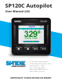
SP120C Autopilot
User Manual (v3)
SI-TEX Main Oce Address:
25 Enterprise Zone Drive, Ste 2
Riverhead, NY 11901
Tel: +1-631-996-2690
Email: [email protected]
Web: www.si-tex.com
IMPORTANT: PLEASE RETAIN ON BOARD

(This page intentionally left blank)

Contents
Warnings 2
Important Installation Notes 3
Installation Tools Required 3
Overview 4
Standard Equipment 4
Additional Equipment Required 4
System Block Diagram 5
System Components / Installation Guides 5
SP120C Control Display Unit 5
Installation Dimensions and Guide 6
Electronic Compass 6-7
Rudder Feedback Unit 8-10
Installation and Wiring 11-13
System Operation
13-14
Steering Modes
13-14
Display Screens 15
System Settings 16
Pilot Settings
16-19
Advanced Menus
20-21
Initial Setup (Installers Instructions) 22
Calibration 22
GPS Settings 25
Other Menu Items 26
SettingUpAndConguringYourGPSSystem 26
Initial Inspection And Testing 28
Dockside Tests 28
Error Messages 29
Alarms 29
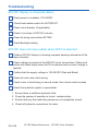
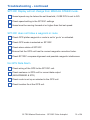
Trouble Shooting
30-31
Warranty 32
Additional Information 33
Contact Information 34

2 of 34
SI-TEX Marine Electronics - SP120C Color Autopilot
Warnings
• The autopilot is a navigational
aid; an adequate watch must
be maintained at all times when
autopilot is in use.
• The autopilot must be placed in
manual mode when the vessel
is stationary as the system may
continue to drive the rudder to the
end of its travel and damage to the
system may result.
• It is strongly recommended that
the autopilot not be used while
navigating in restricted waterways
as water currents, wind changes or
radio transmitter interference can
endanger your own or other vessels.
• It is recommended to install a
rudder feedback unit for best
performance; otherwise the system
will not operate in auto / gps mode
unless the vessel is moving at a
congurableminimumspeed.

3 of 34SI-TEX Marine Electronics - SP120C Color Autopilot
Important Installation
Notes
• Access for wiring must be provided.
cables will possibly need to be
run or extended if required, to the
vessels switchboard, SP120C
display, e-compass, rudder
feedback(iftted)anddriveunit.
• SP120C cables and equipment
must be located as far as possible
from transmitting equipment and
cables (e.g. radio aerials and
aerial cables, radars, inverters,
ect) to prevent electro-magnetic-
interference.
• The e-compass must be mounted a
minimum distance of 1 meter from
other magnetic compasses, radios,
speakers, transmitting equipment
or other products with magnetic
properties, to avoid interference.
• The SP120C must have a direct
connection to power supply via a
15 amp circuit breaker or a 15 amp
fused circuit and an isolating switch.
Installation Tools
Required
•Screwdrivers–atbladeand
phillips head
• Side cutting pliers
• Wire strippers
• Spanners (various) or adjustable
spanner
• 75mm hole saw
• Power drill + assortment of drill bits
• Multi meter (dvm)
• Ancillaries such as tape, terminal
block, screws, cable ties, etc.

4 of 34
SI-TEX Marine Electronics - SP120C Color Autopilot
Overview
Standard Equipment
• SP120C CDU ‘Control Display Unit’
• ELECOM - electronic compass /
e-compass
• RFUS - rudder feedback unit
(optional)
Additional Equipment Required
(not standard supply)
1. Drive motor – to allow the
SP120C to control the vessels
steering system.
• Hydraulic steering systems with
a helm pump and ram will require
one of the following;
• Reversing hydraulic motor/
pump-set, tapped into the
existing hydraulic steering
system or;
• A constant running hydraulic
pump with direction control
solenoids.
A mechanical steering system will
require;
• a reversing mechanical drive,
connected to the existing
steering ram mechanism.
2. Termination hardware;
• Terminal blocks (suitable for
0.75mm
2
and 2.5mm
2
cables)
• Circuit breaker / switch (15A
rated)
• Wiring extension cables / ferrules
/ crimp lugs & related crimp tools
• 2c x 2.5mm
2
for extending motor
and power cables (larger for long
cable runs)
• 1 pair 0.75mm
2
for each nmea
interface cable
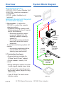
System Block Diagram
12 OR 24 VDC
BATTERY
*CUSTOMER
SUPPLIED
AUTOPILOT
DRIVE UNIT
*CUSTOMER
SUPPLIED
PILOT CONTROL
DISPLAY UNIT
ELECTRONIC
COMPASS
RUDDER
FEEDBACK
UNIT
*OPTIONAL
GPS (NMEA I/F)
*CUSTOMER
SUPPLIED
OPTIONAL
10m SUPPLIED CABLE
30CM FLYLEAD
FOR BATTERY
& MOTOR
CONNECTIONS
CUSTOMER
SUPPLIED
CABLES & TERMINALS
5m SUPPLIED CABLE

5 of 34SI-TEX Marine Electronics - SP120C Color Autopilot
System Components /
Installation Guides
SP120C - Control Display Unit
• Steering control system for 4.0m -
16m vessels;
• ‘Virtual Rudder Feedback’ feature,
where no RFU requires to be
installed.
• 3 Control Modes – Manual Mode,
Auto Mode and GPS mode
• Live indication for ‘Steering mode’,
‘Position & Waypoint Info’, ‘Heading’,
‘Course to Steer’, ‘Rudder angle’,
‘System Voltage’ and ‘Drive Current’
• Supports all current NMEA-0183
interface standards;
• Heading: HDG, HDT, THS, HDM/
ROT & COG
• GPS: APA, APB, XTE, BOD, BWC &
RTR *for GPS steering mode
• GLL, RMC, SOG, VTG *for visual
indication and assisting AUTOPILOT
control
•30cmy-leadfordrivemotorand
power connections
• 6 pin LTW connectors for Compass
and Rudder/NMEA-0183 interfaces
• Power: 12-24 Volts DC (Up to 29V
During Charging)
• Drive output up to 35A. *If current
exceeds 35A, the drive output is
inhibited.
• Software controlled rudder limits,
inhibits drive control at each
mechanical limit.
• Additional auto switching fail
safes, in case of failure of RFU or
E-compass;
• If RFU fails, the system will
revert to Non-RFU mode
automatically.
• If a GPS system is connected
and the standard supplied
E-Compass fails, the SP120C
system will automatically revert
to GPS ‘COG’ mode for heading
reference.

6 of 34
SI-TEX Marine Electronics - SP120C Color Autopilot
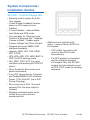
Installation
SP120C CDU Installation
Dimensions
SP120C CDU Installation Guide
- The SP120C Head unit should be
mounted in a position accessible to
the steering position and protected
from direct rain or salt water.
- For in dash mounting cut a 75mm
(3.0”) hole
- An optional mounting bracket
is available and may be used
for desktop mounting - see your
supplier
- Drill mounting screw holes
- Mount the display using screws
supplied (304 SS – 6G)
NOTE: Use the protection cover
when the system is not in use, to
protect the screen and casing from
UV and other physical damage
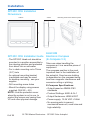
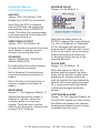
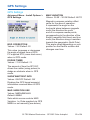
ELECOM
Electronic Compass
(E-Compass V.3)
Take care when handling the
compass as it is a sensitive piece of
equipment.
The compass position is the most
important item in the installation of
the autopilot. Good course holding
is dependent on the compass being
free from magnetic interference and
excessive rolling or pitching.
E-Compass Specications:
• Output based on NMEA 0183
standards
• Protocol Settings: 4800–8–N–1
• Output Sentences: HDM & ROT
• Power supply: 12-24 VDC <1Watt
• No moving parts to prevent
mechanical wear-out, small size and
high reliability.
110mm
43mm
Mounting holes are at 94mm square
110mm

7 of 34SI-TEX Marine Electronics - SP120C Color Autopilot
• Solid state electronics with tilt and
roll compensation up to 35degrees.
E-Compass Installation Guide:
• IMPORTANT! The compass must
bettedinanareaatleast1meter
away from steel objects.
• Avoid positions near radios,
speakers, aerials, antenna cables or
any other current carrying cables.
• Select a dry position free from
magnetic interference.
•Ifsystemisttedtoasteelhull
vessel, the compass must be
mounted at least 1m above the steel
structure on a non-magnetic post or
bracket (aluminium and wood are
good options in this case)
• A lower / aft mounted position along
the centre of the hull is preferred, to
reducetheinuenceofvesselroll
and pitch.
• Check other side of bulkheads and
deck heads for magnetic interfering
type objects before mounting.
• Mount the compass horizontally
with the arrow (bow) pointing to the
front of the vessel, preferably on a
stainless steel, wooden or plastic
bracket.
• Use non-magnetic screws to mount
the compass unit (316 grade
stainless steel)
•Theunitmustbemountedonaat
horizontal surface.
• Before selecting the E-compass
installation position, it is good to
test the installation position is free
from interference by checking the
location with a portable magnetic
compass.
E-Compass Dimensions

8 of 34
SI-TEX Marine Electronics - SP120C Color Autopilot
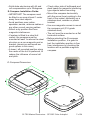
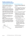
Rudder Feedback Unit
Rudder Feedback Unit (RFUS)
The RFU is optional, although
recommended for the best possible
performance on some types of
vessels.
For example: A RFU must be
installed on vessels with high sides
that are sensitive to winds turning the
boat, or high powered 5-6m Deep V
(22-25 deg dead rise / 175HP+) type
vessels used in rough seas and high
winds. Or any other vessels that are
overly sensitive and very responsive
to small amounts of ‘rudder’ at high
speeds.
When the RFU is installed, the
congurationsettingsaresimplied.
Non-RFU mode is slightly more
complicated.
NOTE: The RFUS is factory aligned.
The arm should not be removed or
loosened. It is also water resistant,
however, if mounted in a wet position
some protection should be provided
to prevent water damage or physical
damage.
RFU Installation Guide
1. Refer to installation diagram and
installation template supplied with
the unit
2. Mount rudder feedback adjacent to
the tiller (NOTE: rudder feedback
movement must copy the angular
movement of the tiller like a
pendulum)
3. Use a mounting bracket if required.
4. Note the markings on the rudder
feedback unit. ‘P & S’ (Port and
Starboard) to check ruder moves
in the correct direction, manually,
before testing on the water.
5. Check installation is suitable
by slowly moving the steering
manually, to ensure:
a. The direction indicated on the
top of the RFU is correct
b. No undue mechanical strain
is placed on the feedback
or linkage. (Also check for
strain when the tiller is tilted
upright (for outboard engine
installations)
6. To complete the install, use the
SP120C advanced menu to
calibrate the rudder limits and
centre point of the RFU.
TMQ RFU-S
RUDDER
FEEDBACK
UNIT
14m Supplied Cable
RFU 5V
RED
RFU WIPER
GRN
RFU av
BLU
5
6 0
0
0
4
CONNECT TO
AP47C
RUDDER
LTW-6PIN

9 of 34SI-TEX Marine Electronics - SP120C Color Autopilot
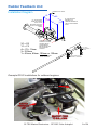
X1 = X2
Y1 = Y2
A = Y2 + 15mm
X < 325mm
Y = 55mm, 80mm, 105mm or 130mm
Y1
X1
X2
Y2
A
ALIGN BOTH THE
RUDDER TILLER ARM
AND RFU ARM TO
CENTER MARKS
BEFORE SELECTING
RFU MOUNTING
POSITION
RECOMMEND USING
105mm DISTANCE
A = THE DISTANCE
FROM THE RUDDER
PIVOT TO THE
MOUNTING HOLE FOR
THE RFU ADJUSTMENT
BLOCK
HYDRAULIC RAM
X = THE DISTANCE
BETWEEN THE
TURNING CENTERS OF
THE RFU AND RUDDER
SHAFT
RFU INSTALLATION KIT
RFU ADJUSTMENT BLOCK
32mm M5 BOLT, WASHERS &
NUTS
BALL JOINT
QUICK RELEASE
SOCKET.
RUDDER PIVOT POINT
300mm S/S LINKAGE
Rudder Feedback Unit
Installation Diagram
Example RFUS installations for outboard engines:

10 of 34
SI-TEX Marine Electronics - SP120C Color Autopilot
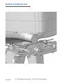
Rudder Feedback Unit

11 of 34SI-TEX Marine Electronics - SP120C Color Autopilot
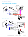
RED
BLK
YEL
YEL/BLK
GRN
POWER +VE
POWER -VE
MOTOR
MOTOR
CLUTCH
E-COMPASS
GPS (NMEA0183)
SWITCH OR
CIRCUIT
BREAKER
(15A)
REVERSING
PUMP
OR LINEAR
DRIVE UNIT
CLUTCH
OUTPUT
IS -VE
SWITCHED
COMMON
+VE FOR
CLUTCH
SOLENOID
AUTOPILOT
SOLENOIDS
TMQ RFU-S
RUDDER
FEEDBACK
UNIT
CUSTOMER
SUPPLIED
CABLES
12 OR 24 VDC
BATTERY
*CUSTOMER
SUPPLIED
RED
BLK
YEL
YEL/BLK
GRN
POWER +VE
POWER -VE
MOTOR
MOTOR
CLUTCH
E-COMPASS
GPS (NMEA0183)
SWITCH OR
CIRCUIT
BREAKER
(15A)
TMQ RFU-S
RUDDER
FEEDBACK
UNIT
5M SUPPLIED CABLE
CUSTOMER
SUPPLIED
CABLES
12 OR 24 VDC
BATTERY
*CUSTOMER
SUPPLIED
RED
BLK
YEL
YEL/BLK
GRN
POWER +VE
POWER -VE
MOTOR
MOTOR
CLUTCH
E-COMPASS
GPS (NMEA0183)
SWITCH OR
CIRCUIT
BREAKER
(15A)
REVERSING
PUMP
OR LINEAR
DRIVE UNIT
CLUTCH
OUTPUT
IS -VE
SWITCHED
COMMON
+VE FOR
CLUTCH
SOLENOID
AUTOPILOT
SOLENOIDS
TMQ RFU-S
RUDDER
FEEDBACK
UNIT
CUSTOMER
SUPPLIED
CABLES
12 OR 24 VDC
BATTERY
*CUSTOMER
SUPPLIED
RED
BLK
YEL
YEL/BLK
GRN
POWER +VE
POWER -VE
MOTOR
MOTOR
CLUTCH
E-COMPASS
GPS (NMEA0183)
SWITCH OR
CIRCUIT
BREAKER
(15A)
TMQ RFU-S
RUDDER
FEEDBACK
UNIT
5M SUPPLIED CABLE
CUSTOMER
SUPPLIED
CABLES
12 OR 24 VDC
BATTERY
*CUSTOMER
SUPPLIED
Installation & Wiring
Reversing pump or linear drive systems
Solenoid Controlled Systems

12 of 34
SI-TEX Marine Electronics - SP120C Color Autopilot
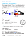
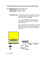
Wiring Information
Solenoid Valves - Important Information
Ifanemergencyjogleveristtedthenthemotoroutputsmustbeisolated!to
prevent damage to the drivers. To isolate, a 2 pole change over relay must be
installed between the SP120C and the Solenoids, as per diagram below;
Also as a preventative measure to ensure voltage spikes do not interfere with
the AUTOPILOT or other equipment, spike suppression diodes should be
ttedonsolenoidvalves.
Rudder Connector
Pin connections from rear of plug, solder connection side.
NOTE: Pin 1 has dot adjacent.
Pin 1 5V RFU Supply
Pin 2 RFU Wiper
Pin 3 0V RFU Supply / TX- RS-232 GND
Pin 4 TX+ RS-232 Data + (heading information)
Pin 5 + GPS Input (Positive)
Pin 6 - GPS Input (Negative)
Supplied GPS Cable (for NON-RFU models)
Thestandardsystemissuppliedwithashort4core30cmy-lead,for
wiring direct to a GPS unit. See below for the color codes used for external
connections;
NMEA input from GPS:
Pin 5 +GPS Input (Positive) White wire
Pin 6 - GPS Input (Return) Green wire
NMEA output for Heading data to external systems:
Pin 4 + Heading Data Out (Positive) - Red wire
Pin 3 - Heading Data Out (Negative) - Blue wire (0 volt line)
NOTE: For further interfacing information, refer to the installation manual
supplied with your GPS unit.
RED
BLK
YEL
YEL/BLK
GRN
NC1
NO1
C1
NC2
NO2
C2
POWER +VE
POWER -VE
MOTOR
MOTOR
CLUTCH
SWITCH OR
CIRCUIT
BREAKER
(15A)
12V OR 24V DC
2PDT RELAY
12/24VDC
BATTERY
+VE
12/24VDC
BATTERY
-VE
STEERING SOLENOID (PORT)
STEERING SOLENOID (STBD)
JOG LEVER
1
6
5
2
3
4
RED
BLK
YEL
YEL/BLK
GRN
POWER +VE
POWER -VE
MOTOR
MOTOR
CLUTCH

13 of 34SI-TEX Marine Electronics - SP120C Color Autopilot
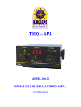
Wiring Information - continued
Rudder Feedback Unit Wiring
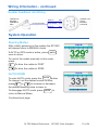
System Operation
Steering Modes
After initially powering on the system the SP120C
will always return to MANUAL mode
If AUTO or GPS mode is active, press
AUTO
once to return.
To control the rudder manually in this mode,
press;
To drive the rudder to PORT
To drive the rudder to STBD
AUTO MODE
To enter AUTO mode, press the button
To change / set the desired course to steer,
press
or
to increase or decrease
the desired heading value to steer to.
To disengage AUTO mode, press
AUTO
to
return to Manual Mode.
Continued next page
AUTO
TMQ RFU-S
RUDDER
FEEDBACK
UNIT
14m Supplied Cable
RFU 5V
RED
RFU WIPER GRN
RFU av
BLU
5
6 0
0
0
4
CONNECT TO
AP47C
RUDDER
LTW-6PIN

14 of 34
SI-TEX Marine Electronics - SP120C Color Autopilot
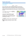
System Operation
Steering Modes - Continued
GPS MODE
To enter GPS mode, press both
MODE
&
AUTO
simultaneously
Before enabling this mode, ensure the GPS system has an activated
waypoint, cursor or route, for the SP120C to follow. The boat will change
course to steer at the maximum rate of turn, so it is recommended to ensure
thevesselisheadingtowardstherstGPStargetatasuitablespeedbefore
enabling.
To disengage GPS mode, press
AUTO
to
return to Manual Mode.
In this mode, the AUTOPILOT must be
interfaced to a GPS generating NMEA
0183 data output The GPS will also require
congurationtoensurecorrectsentences
and settings are suitable.
To DODGE an obstacle while in GPS Mode Press;
To dodge by steering the vessel to PORT
To dodge by steering the vessel to STBD

15 of 34SI-TEX Marine Electronics - SP120C Color Autopilot
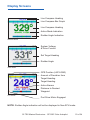
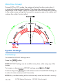
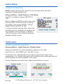
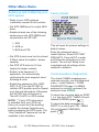
Display Screens
Manual Mode
Auto Mode
GPS Mode
Live Compass Heading
System Voltage
& Drive Current
Live Compass Bar Graph
Live Compass Heading
Set Target Heading
Active Mode Indication
Rudder Angle
GPS Position (LAT/LONG)
Amount of Deviation from
Target Heading
Target Heading
Active Alarms
Distance to Desired
Waypoint
Port Drive Motor Engaged
Rudder Angle Indication
NOTE: Rudder Angle indication will not be displayed in Non-RFU mode.

16 of 34
SI-TEX Marine Electronics - SP120C Color Autopilot
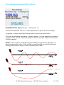
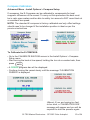
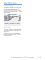
Motor Drive Concept
During AUTO or GPS modes, the system will pulse the drive motor when it
is close to the desired target heading. This allows the system to make minor
adjustments to the rudder to stay on course. Also note the dead band (relating
to the rudder sense setting) this accounts for excessive play in the rudder and
reducestherudder‘hunting’eect.
System Settings
Pilot Settings
To access the SP120C Settings menu
Press the
MODE
button.
NOTE: SP120C Settings can be modied at any time, while using any of the
modes.
To increase or decrease any SP120C settings press
or
Continuously press
MODE
to scroll between each of the SP120C Settings, or
to return to main screen (or wait 5 seconds).
NOTE: Any modied setting will be automatically saved and stored in memory.

17 of 34SI-TEX Marine Electronics - SP120C Color Autopilot
Pilot Settings Explained (RFU Mode)
RUDDER RATIO (Gain) Range: 1-40 Default: 15
Controlstheamountofdrive/rudderappliedforagiveno-courseangle.
In general, a vessel with fast turning rate will require a lower value.
This may be adjusted according to vessel speed. I.e. Low speeds may require
a higher value, as the vessel will respond slower to larger rudder movements
at lower speeds.
NOTE: If the vessel is understeering and taking a long time to get back on
track, increase this value. If the vessel is over-steering or overshooting and
making hard turns to stay on track, decrease this value.

18 of 34
SI-TEX Marine Electronics - SP120C Color Autopilot
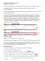
RUDDER SENSE (Sensitivity)
Range: 1-10 Default: 1
Theacceptableamountofo-courseerrorallowedforminorruddercorrections.
Increasing this value reduces the amount of pulses used to keep the
vessel on course.
If the vessels rudder is continuously hunting, always increase this value to avoid
damaging the drive unit.
This value should also be increased in poor weather conditions. For example,
when going up a wave the vessels course may move +6 degrees, on the way
down the vessel corrects itself -6 degrees naturally, therefore Rudder Sense
value should be increased. Otherwise, the SP120C will correct the course
change and drive the rudder on the way up the wave, in turn causing the vessel
to oversteer when moving down the wave, therefore resulting in excessive
unnecessary rudder corrections.
RATE OF TURN
Range: 10-720 (degrees/min) Default: 700
Limits the rudder drive when the SP120C detects the vessel is turning too fast.
I.e. if the rate of change in heading exceeds this value, the SP120C system
limits the rudder drive to limit high speed turns. If this setting is too low, the
vessel may understeer when changing course.
Backlight Bright
Controls the brightness and display mode of the LCD display.
To switch between Day/Night modes;
Select the BACKLIGHT BRIGHT setting using the
MODE
button;
To switch to Night mode or dim the LCD screen, press and/or hold
ToswitchtoDAYmodeandincreasebrightness,pressand/orhold
Page is loading ...
Page is loading ...
Page is loading ...
Page is loading ...
Page is loading ...
Page is loading ...
Page is loading ...
Page is loading ...
Page is loading ...
Page is loading ...
Page is loading ...
Page is loading ...
Page is loading ...
Page is loading ...
Page is loading ...
Page is loading ...
-
 1
1
-
 2
2
-
 3
3
-
 4
4
-
 5
5
-
 6
6
-
 7
7
-
 8
8
-
 9
9
-
 10
10
-
 11
11
-
 12
12
-
 13
13
-
 14
14
-
 15
15
-
 16
16
-
 17
17
-
 18
18
-
 19
19
-
 20
20
-
 21
21
-
 22
22
-
 23
23
-
 24
24
-
 25
25
-
 26
26
-
 27
27
-
 28
28
-
 29
29
-
 30
30
-
 31
31
-
 32
32
-
 33
33
-
 34
34
-
 35
35
-
 36
36


Si-tex SP120C User manual
- Category
- Navigational compasses
- Type
- User manual
Ask a question and I''ll find the answer in the document
Finding information in a document is now easier with AI
Related papers
Other documents
-
 OMIX 19101.04 Installation guide
-
 OMIX 19101.03 Installation guide
-
 TMQ AP4 Operation and Installation Manual
-
Garmin Nexus Owner's manual
-
Navman G-PILOT 3100 User manual
-
Simrad Autopilot Buyers Getting Started
-
 TMQ AP9 Operation and Installation Manual
-
Raymarine Marine Instruments ST6002 User manual
-
Transcend TSCBU2 Datasheet
-


