Page is loading ...

SWING ARM
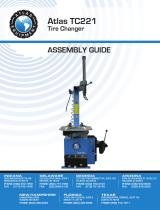
TIRE CHANGER
INS TRUCTIONS
Item #31638

2 Eastwood Technical Assistance: 800.343.9353 >> techelp@eastwood.com
The Eastwood Tire Changer offers the ability to quickly and easily mount and dismount tires on most any steel or alloy wheels without damage. Constructed with
the same pneumatic functions as other professional machines, this Tire Machine is ideal for the avid home hobbyist, race shop or small business.
CONTENTS
(1) Main Tire Machine Base Unit - [A]
(1) Vertical Tower - [B]
(4) M12 Nuts - [C]
(4) M12 Washers - [D]
(1) Slide Shaft Spring - [E]
(1) Plastic Cover - [F]
(20) Mount/Dismount Shoe “Duckhead” Replaceable Plastic Glides – [G]
(20) Mount/Dismount Shoe “Ducktail” Replaceable Plastic Glides – [H]
(1) Coiled Air Hose - [J]
(1) Gauge/Fill Gun - [K]
(1) 1/4” MNPT, Male Coupler – [L]
(1) Tire Iron – [M]
(4) Rim Protectors – [N]
SPECIFICATIONS
Rim Diameter Range:
– External Clamping: 10” to 18”
– Internal Clamping: 12” to 21”
Maximum Rim Width: 16”
Maximum Tire Diameter: 45”
Turntable Rotation Speed: 6 RPM
Power Requirements: 120 VAC, 60hz
Air Supply Operational Range: 115 to 145 PSI [8 to 10 Bar]
TOOLS REQUIRED
• 17mm Wrench
• 16mm Wrench
• 8mm Hex Key
• 3mm Hex Key
• 2mm Hex Key

DANGER indicates a hazardous situation which, if not avoided, will result in death or serious injury.
WARNING indicates a hazardous situation which, if not avoided, could result in death or serious injury.
CAUTION used with the safety alert symbol, indicates a hazardous situation which, if not avoided, could result in minor or moderate injury.
NOTICE is used to address practices not related to personal injury.
SAFETY INFORMATION
The following explanations are displayed in this manual, on the labeling, and on all other information provided with this product:
GENERAL SAFETY RULES
Read all instructions. Failure to follow all instructions listed below may result in electric shock, fire and/or serious injury. The term “electrical equipment ” in all
of the warnings listed below refers to your mains-operated (corded) power tool or battery-operated (cordless) power tool.
SAVE THESE INSTRUCTIONS
1) WORK AREA SAFETY
a) Keep work area clean and well lit. Cluttered or dark areas invite accidents.
b) Do not operate electrical equipment in explosive atmospheres, such as in the presence of flammable liquids, gases or dust. Electrical equipment creates
sparks which may ignite the dust or fumes.
c) Keep children and bystanders away while operating electrical equipment. Distractions can cause you to lose control.
2) ELECTRICAL SAFETY
a) Electrical equipment plugs must match the outlet. Never modify the plug in any way. Do not use any adapter plugs with earthed (grounded) electrical
equipment. Unmodified plugs and matching outlets will reduce risk of electric shock.
b) Avoid body contact with earthed or grounded surfaces such as pipes, radiators, ranges and refrigerators. There is an increased risk of electric shock
if your body is earthed or grounded.
c) Do not expose electrical equipment to rain or wet conditions. Water entering electrical equipment will increase the risk of electric shock.
d) Do not abuse the cord. Never use the cord for carrying, pulling or unplugging the electrical equipment. Keep cord away from heat, oil, sharp edges or
moving parts. Damaged or entangled cords increase the risk of electric shock.
e) When operating electrical equipment outdoors, use an extension cord suitable for outdoor use. Use of a cord suitable for outdoor use reduces the risk
of electric shock.
To order parts and supplies: 800.343.9353 >> eastwood.com 3

4 Eastwood Technical Assistance: 800.343.9353 >> techelp@eastwood.com
3) PERSONAL SAFETY
a) Stay alert, watch what you are doing and use common sense when operating electrical equipment. Do not use electrical equipment while you are tired or
under the influence of drugs, alcohol or medication. A moment of inattention while operating electrical equipment may result in serious personal injury.
b) Use safety equipment. Always wear eye protection. Safety equipment such as dust mask, non-skid safety shoes, hard hat, or hearing protection used
for appropriate conditions will reduce personal injuries.
c) Avoid accidental starting. Ensure the switch is in the off-position before plugging in. Carrying electrical equipment with your finger on the switch or
plugging in electrical equipment that have the switch on invites accidents.
d) Remove any adjusting key or wrench before turning the electrical equipment on. A wrench or a key left attached to a rotating part of the electrical
equipment may result in personal injury.
e) Do not overreach. Keep proper footing and balance at all times. This enables better control of the electrical equipment in unexpected situations.
f) Dress properly. Do not wear loose clothing or jewelry. Keep your hair, clothing and gloves away from moving parts. Loose clothes, jewelry or long hair
can be caught in moving parts.
g) If devices are provided for the connection of dust extraction and collection facilities, ensure these are connected and properly used. Use of these devices
can reduce dust-related hazards.
4) POWER TOOL USE AND CARE
a) Do not force the electrical equipment. Use the correct electrical equipment for your application. The correct electrical equipment will do the job better
and safer at the rate for which it was designed.
b) Do not use the electrical equipment if the switch does not turn it on and off. Any electrical equipment that cannot be controlled with the switch is
dangerous and must be repaired.
c) Disconnect the plug from the power source and/or the battery pack from the electrical equipment before making any adjustments, changing accessories,
or storing electrical equipment. Such preventive safety measures reduce the risk of starting the electrical equipment accidentally.
d) Store idle electrical equipment out of the reach of children and do not allow persons unfamiliar with the electrical equipment or these instructions to
operate the electrical equipment. Electrical equipment is dangerous in the hands of untrained users.
e)
Maintain electrical equipment. Check for misalignment or binding of moving parts, breakage of parts and any other condition that may affect the electrical
equipment operation. If damaged, have the electrical equipment repaired before use. Many accidents are caused by poorly maintained electrical equipment.
f) Keep cutting tools sharp and clean. Properly maintained cutting tools with sharp cutting edges are less likely to bind and are easier to control.
g) Use the electrical equipment, accessories and tool bits etc., in accordance with these instructions and in the manner intended for the particular type of
electrical equipment, taking into account the working conditions and the work to be performed. Use of the electrical equipment for operations different
from those intended could result in a hazardous situation.
5) SERVICE
a) Have your electrical equipment serviced by a qualified repair person using only identical replacement parts. This will ensure that the safety of the electrical
equipment is maintained.
SAFETY INFORMATION

To order parts and supplies: 800.343.9353 >> eastwood.com 5
TIRE MACHINE SAFETY FEATURE
INSTALLATION LOCATION
• The Tire Machine MUST be installed on a solid and level concrete or similar surface for proper operation, accuracy and safety.
• There MUST be a minimum of 3 ft. of open space surrounding the Tire Machine.
• This Tire Machine MUST be firmly attached to the floor with suitable concrete anchors or similar hardware (not included).
Should a malfunction occur during the operation of the Tire Machine, releasing foot pressure from controls will stop motion
immediately.
PINCH AND CRUSH HAZARD!
• Keep fingers and hands away from moving parts when operating.
CUT HAZARD!
• Contacting metal edges on wheels can cause serious cuts. Wear thick, well-fitting work gloves to prevent cuts from handling wheels & tires.
INJURY HAZARD!
• This tool can quickly start up while connected to an electrical supply causing serious personal injury. Always disconnect the
Tire Machine from the electrical supply before making adjustments or performing maintenance.
• The Tire Machine involves the mounting/dismounting of large, heavy wheel/tire combinations which can cause serious injuries
if dropped. The use of safety shoes is strongly recommended.
EYE INJURY HAZARD!
• Moving/rubbing components under great pressures can suddenly eject particles at high velocity. Always wear ANSI approved eye
protection when operating this equipment.
BURST HAZARD!
• Excessive air pressure can cause tool to explode resulting in tool damage and personal injury. Do not exceed 145 psi [10 bar]
of tool inlet air pressure.
INJURY HAZARD!
• The Tire Machine consists of large moving components which can present a hand/finger pinch hazard injuries if dropped.
Avoid pinching hands while handling parts during assembly and/or operation.
• The Tire Machine was specifically designed to be operated by one person only. Never have one person operate the pedals while
another handles the wheel mounting/dismounting or serious injury could occur.
• Inspect rim and tire before mounting or dismounting for damaged or bent conditions. Attempting to mount or dismount a damaged
rim and/or tire can result in serious injury and severe Tire Mounting Machine damage.
• Wheels and tires MUST be clean and free of all mud, grit, rust or other debris as this can cause machine malfunction and failure
of tires to seal.
SAFETY INFORMATION

6 Eastwood Technical Assistance: 800.343.9353 >> techelp@eastwood.com
TIRE MACHINE FEATURE DESCRIPTIONS
“aa” Lock Lever
“bb” Slide Shaft
“cc” Spring Cap
“dd” Mount/Dismount Shoe
“ee” Air Regulator/Oiler
“ff” Cushion Block
“gg” Bead Breaker Blade
“hh” Bead Breaker Pedal
“jj” Turntable
“kk” Rim Clamps
“mm” Rim Clamp Pedal
“nn” Wheel Diameter Adjustment Knob
“pp” Turntable Pedal
“aa”
✓
FIG. A
“bb”
✓
“Ducktail”
✓
“dd”
✓
“cc”
✓
✓
✓
✓
✓
✓
✓
✓
✓
✓
✓
✓
✓
✓
✓
F
E
K
J
H
“kk”
✓
G
“Duckhead”
M
“ff”
“gg”
“jj”
✓
✓
✓
C/D
“ee”
L
A
✓
✓
✓
✓
B

To order parts and supplies: 800.343.9353 >> eastwood.com 7
“aa”
F
✓
✓
✓
✓
✓
✓
“cc”
“bb”
“dd”
“jj”
“kk”
✓
✓
✓
“gg”
✓
✓
M
“ff”
✓
“hh”
“mm”
✓
“pp”
A
B
“nn”
“kk”
✓
✓
✓
✓
E
FIG. B
✓
✓
✓

8 Eastwood Technical Assistance: 800.343.9353 >> techelp@eastwood.com
ASSEMBLY
VERTICAL TOWER [B] TO MAIN BASE UNIT [A] Reference FIGS A AND B
• Place the square flange of the Vertical Tower [B] onto the Main Base Unit [A] with the four corner holes aligned over the four M12 studs of the
Main Base Unit. Note that the Pivoting Arm of the Vertical Tower must face the front end of the Main Base Unit.
• Use the four M12 Nuts [C] and Washers [D] and tighten securely with a 17mm wrench (not included).
SLIDE SHAFT SPRING [E] TO SLIDE SHAFT “BB” Reference FIGS A AND B
Remove the M10 Socket Head Cap Screw and the Spring Cap “cc” from the top of the Slide Shaft with an 8mm Hex Key (not included) and set aside “for
re-installation.
• Rotate the Lock Lever “aa” 90° from a vertical position down to horizontal to unlock the Slide Shaft “bb”.
• Raise the Slide Shaft “bb” fully, rotate the Lock Lever “aa” up 90° to a vertical position to lock the Slide Shaft in place.
• Slip the Slide Shaft Spring [E] down over the Slide Shaft “bb”.
• Re-install the Plastic Spring Retaining Cap “cc” over the end of the Slide Shaft and re-install the M10 Socket Head Cap Screw.
NOTE: Some moderate pressure may be required to hold the Spring Cap “cc” in place while installing screw.
• Slip the Plastic Cover [F] down over the Slide Shaft and snap into place on the metal
bracket of the Lock Lever assembly.
INSTALL MOUNT/DISMOUNT SHOE, HORIZONTAL [G] AND VERTICAL [H] PLASTIC GLIDES
• Snap the Mount/Dismount Shoe “dd”, “Ducktail” Replaceable Plastic Glide [G]
(smaller Glide) into the horizontal slot of the Mount/Dismount Shoe (FIG 1).
• Install the Mount/Dismount Shoe “Duckhead” Replaceable Plastic Glide [H]
(larger Glide) into the vertical recess of the Mount/Dismount Shoe
(FIGS 2&3) by removing the retaining set-screw with a 2mm hex key (not included).
INJURY HAZARD!
• The Tire Machine consists of large moving components which can present hand/finger pinch hazard injuries if dropped.
• Avoid pinching hands while handling parts during assembly and/or operation.
Never operate the Tire Changing Machine without these Glides in place
or severe damage to the wheel rim edge and face will occur.
FIG. 1
FIG. 2
FIG. 3
✓
G
“dd”
✓
“dd”
✓
✓
H
Duckhead
Set Screw
Ducktail
H
“dd”
G
✓
✓
✓
✓
✓
✓
PINCH AND CRUSH HAZARD!
Keep fingers and hands away from moving parts when operating.

To order parts and supplies: 800.343.9353 >> eastwood.com 9
PINCH AND CRUSH HAZARD!
Keep fingers and hands away from moving parts when operating.
BURST HAZARD!
Excessive air pressure can cause tool to
explode resulting in tool damage and
personal injury. Do not exceed 145 psi
[10 bar] of tool inlet air pressure.
COILED AIR HOSE [J] AND GAUGE/FILL GUN [K]
• Rotate the Threaded, Slotted Ferule located on the air
inlet at the bottom of the Gauge/Fill Gun [K] in a “loosen”
direction then slide the Flanged Brass Fitting on the end of
the Coiled Air Hose [J] into the open slot then tighten the
Ferrule to tightly retain the Flanged Brass Fitting (FIG 4).
• Rotate the Threaded, Slotted Ferule located on the air outlet at the rear, lower right corner of the Mounting Machine in a “loosen” direction then slide the
Flanged Brass Fitting on the end of the Coiled Air Hose [J] into the open slot, then tighten the Ferrule to tightly retain the Flanged Brass Fitting.
1/4” MNPT, MALE COUPLER [L]
• Thread the 1/4" MNPT Male Coupler into the air inlet port of the included Air Regulator/Oiler “ee”. Apply Teflon
®
tape to the threads to ensure
a leak-free seal. Do not over-tighten.
TIRE CHANGER OPERATION
Note that the Tire Changer has three main functions that are explained in the following three segments:
– “Breaking” the tire bead seal.
– Dismounting a tire from a wheel rim.
– Mounting a tire on a wheel rim.
Before beginning any work with the Tire Changer, the Air Regulator/Oiler “ee” should be set to a maximum of 145 PSI [10 Bar] Maximum of operating inlet air
pressure by connecting to a clean and dry air supply then pushing down and turning the knob on the Air Regulator Clockwise or Counterclockwise as required.
FIG. 4
K
✓
✓
✓
JFerrule
CUT HAZARD!
Contacting metal edges on wheels can cause serious cuts. Wear thick, well-fitting work gloves to prevent cuts from handling
wheels & tires.
INJURY HAZARD!
This tool can quickly start up while connected to an electrical supply causing serious personal injury. Always disconnect the
Tire Machine from the electrical supply before making adjustments or performing maintenance.
EYE INJURY HAZARD!
Moving/rubbing components under great pressures can suddenly eject particles at high velocity. Always wear ANSI approved
eye protection when operating this equipment.
BURST HAZARD!
Excessive air pressure can cause tool to explode resulting in tool damage and personal injury. Do not exceed 145 psi [10 bar] of
tool inlet air pressure.
INJURY HAZARD!
The Tire Machine involves the mounting/dismounting of potentially large, heavy wheel/tire combinations which can present
potentially serious injuries if dropped. The use of safety shoes is strongly recommended.

10 Eastwood Technical Assistance: 800.343.9353 >> techelp@eastwood.com
INJURY HAZARD!
The Tire Machine consists of large moving components which can present a hand/finger pinch hazard injuries if dropped.
Avoid pinching hands while handling parts during assembly and/or operation.
The Tire Machine was specifically designed to be operated by one person only. Never have one person operate the pedals while
another handles the wheel mounting/dismounting or serious injury could occur.
INJURY HAZARD!
Inspect rim and tire before mounting or dismounting for previous damage or bent conditions. Attempting to mount or dismount
a damaged rim and/or tire can result in serious injury and severe Tire Mounting machine damage.
“BREAKING” THE TIRE BEAD SEAL
• Using a Valve Stem Core Removing Tool (not included) remove the valve stem core by unthreading and pulling it out to release all air from the tire.
• Place the deflated tire and wheel rim vertically
against the Rubber Cushion Block “ff” located on
the lower, right side of the Tire Machine (FIG 5).
• Keeping hands free of the entire tire and wheel rim,
use the Handle of the Bead Breaking Blade “gg”
to pivot it to a position where the curved edge is in
the same alignment as the curve of the wheel rim.
At the same time, set the wheel and tire so that the
edge of the rim is 1/4” to 3/8” from the edge of the
Bead Breaking Blade (FIG 5).
INJURY HAZARD!
To decrease the possibility of personal injury and damage to the tire and wheel, it is vitally important that all air first be released
from the tire before beginning any work.
DO NOT allow the edge of the Bead
Breaking Blade “gg” to come in contact
with the wheel rim or serious damage
to the tire and rim as well as the Bead
Breaking Blade will occur.
On vehicles equipped with remote tire
pressure sensors, use extreme care not
to press the Bead Breaking Blade “gg”
in the vicinity of the valve stem and
sensor or the sensor may be destroyed.
FIG. 5
“gg”
✓

To order parts and supplies: 800.343.9353 >> eastwood.com 11
FIG. 6
FIG. 7
• Slowly and carefully depress the Bead Breaker
Pedal “hh” located at the right of the 3 pedal clus-
ter at the lower front of the Tire Machine (FIG 6).
• Pneumatic force will push the tire bead in and
separate it from the wheel rim bead area (FIG 7).
Release the Bead Breaker Pedal “hh” as soon as
this occurs.
• Release all Bead Breaking Blade pressure and
contact, re-position the tire and wheel and repeat
above process as needed to fully separate the tire
bead from the rim. Reversing the tire and rim may
be required to unseat the bead from the back side
of the wheel rim.
Failure to discontinue Bead Breaking
Blade “gg” pressure on the tire can
cause permanent damage to the tire
sidewall and internal cord material.
“gg”
✓
“pp” “mm” “hh”
Turntable
Pedal
Rim Clamp
Pedal
Bead Breaker
Pedal
✓
✓
✓
On vehicles equipped with remote
tire pressure sensors, use extreme
care not to press the Bead Breaking
Blade “gg” in the vicinity of the valve
stem and sensor or the sensor may
be destroyed.

12 Eastwood Technical Assistance: 800.343.9353 >> techelp@eastwood.com
FIG. 8
FIG. 9
FIG. 10
DISMOUNT TIRE FROM THE WHEEL RIM
• First, remove all clip-on balance weights from the
wheel rim with a suitable wheel weight removal tool
(not included).
• Place the wheel and tire face-up on the Turntable
“jj”.
• Using a suitable applicator (not included) apply tire
bead lubricant or soap solution to the tire bead.
• Operate the four Rim Clamps “kk” of the Turntable
“jj” (FIG 8) by depressing the Rim Clamp Pedal
“mm” located in the center of the 3 pedal cluster
(FIG 6).
• Depressing the Rim Clamp Pedal “mm” will move
them outward and engage the teeth of the Rim
Clamps “kk” with the inner surface of the wheel
rim.
• Release the Lock Lever
“aa”
by rotating it 90° from
a vertical position down to horizontal to unlock the
Slide Shaft
“bb”
.
• Allow the Mount/Dismount Shoe “Ducktail” Plastic
Glide [H] to stop just above the face of the rim then
lock the Slide Shaft.
• Rotate the Wheel Diameter Adjustment Knob “nn”
(FIG 9)
inward or outward to determine the distance
of the “Duckhead” Plastic Glide [G] of the Mount/
Dismount Shoe in relation to the edge of the wheel
rim bead area (FIG 10).
• With the position of the Mount/Dismount Shoe
properly set, the “Ducktail” Plastic Glide [H]
surface will be from 1/16” to 1/8” away from the
front face of the wheel rim and the “Duckhead”
Plastic Glide [G] surface will be from 1/16” to 1/8”
away from the outer diameter edge of the wheel
rim bead (FIG 10).
Plastic Rim Protectors [N] (Fig 8) are
shown in place over the Rim Clamps
“kk” to protect wheel rims from
being damaged.
Failure to apply a lubricant can cause
tire bead damage and add unnec-
essary strain to the Tire Machine
components.
It is important to recall that the Rim
Clamps are operated by depressing
the Rim Clamp Pedal once to move
them outward on the Turntable while
depressing the pedal a second time
reverses the clamp travel inward
toward the center of the Turntable.
✓
N
✓
“kk”
✓
✓
Out
In
“jj”
“nn”
✓
“dd”
G
1/16" to 1/8"
1/16" to 1/8"
H
✓
✓
✓
✓
✓
✓
✓
Out In
✓
✓

To order parts and supplies: 800.343.9353 >> eastwood.com 13
FIG. 11
• Place the Tire Iron [M], under the tire bead and
over the rounded beak of the “Duckhead” portion
of the Mount/Dismount Shoe “dd” and use it to
pull the tire bead up and over the entire Mount/
Dismount Shoe (FIG 11).
• At this point, hold the Tire Iron [M] in place and
depress the Turntable Pedal “pp” located at the left
of the 3 pedal cluster. This will cause the Turntable
to rotate in a Clockwise direction and the Mount/
Dismount Shoe will pull the tire bead off the wheel
rim (FIG 12).
• Pull the tire up so the inner tire bead is now under
the outer bead section of the wheel rim (FIG 13).
• Repeat the above several steps once again using
the Mount/Dismount Shoe and Tire Iron to pull the
inner tire bead off the rim (FIG 13).
• Unlock the Slide Shaft, raise it and remove tire.
Lifting the Turntable Pedal with
the toe of your shoe will rotate the
Turntable in the opposite Counter-
Clockwise direction.
FIG. 12
FIG. 13
✓
M

14 Eastwood Technical Assistance: 800.343.9353 >> techelp@eastwood.com
MOUNTING TIRE ON THE WHEEL RIM
• Be sure the bead area of the rim is clean and free of
rust, corrosion, old tire remnants or other debris as
failure to do so will prevent a good bead seal.
• Place the wheel face-up on the Turntable “jj”.
• Operate the four Rim Clamps “kk” of the Turntable
“jj” by depressing the Rim Clamp Pedal “mm”
located in the center of the 3 pedal cluster (FIG 6).
• Depressing the Rim Clamp Pedal “mm” will move them outward and engage the teeth of the Rim Clamps “kk” with the inner surface of the wheel rim.
• Release the Lock Lever by rotating it 90° from a vertical position down to horizontal to unlock the Slide Shaft.
• Allow the Mount/Dismount Shoe, “Ducktail” Plastic Glide [H] to stop just above the face of the rim then lock the Slide Shaft.
• Rotate the Wheel Diameter Adjustment Knob “nn” inward or outward to determine the distance of the “Duckhead” Plastic Glide [G] of the
Mount/Dismount Shoe in relation to the edge of the wheel rim bead area (FIGS 9 & 10).
• If desired, install a new Valve Stem (not included) into the Wheel Rim.
• Using a suitable applicator (not included) apply tire bead lubricant or soap solution liberally to the tire bead.
• Place the inner side of the tire over the outer face of the wheel rim with the bead slipped over the side and under the Mount/Dismount Shoe.
• At this point, depress the Turntable Pedal “pp” located at the left of the 3 pedal cluster. This will cause the Turntable to rotate in a Clockwise direction
and the tail of the Mount/Dismount Shoe will push the tire bead onto the wheel rim. Grasping the tire by the tread area and lifting/pulling may help the
process (FIG 14).
• Repeat the 2 preceding steps with the outer bead of the tire to complete the mounting process.
FIG. 14
Plastic Rim Protectors (N) are in
place over the Rim Clamps “kk” to
protect wheel rims from being dam-
aged.
It is important to recall that the Rim
Clamps are operated by depressing
the Rim Clamp Pedal once to move
them outward on the Turntable while
depressing the pedal a second time
reverses the clamp travel inward
toward the center of the Turntable.
Failure to apply a lubricant can cause tire bead damage and add unnecessary strain to the Tire Machine components.
Lifting the Turntable Pedal with the toe of your shoe will rotate the Turntable in the opposite Counter-Clockwise direction if needed.

To order parts and supplies: 800.343.9353 >> eastwood.com 15
MAINTENANCE
PINCH AND CRUSH HAZARD!
Keep fingers and hands away from moving parts when operating.
INJURY HAZARD!
This tool can quickly start up while connected to an electrical supply causing serious personal injury. Always disconnect the
Tire Machine from the electrical supply before making adjustments or performing maintenance.
EYE INJURY HAZARD!
Moving/rubbing components under great pressures can suddenly eject particles at high velocity. Always wear ANSI approved
eye protection when operating this equipment.
BURST HAZARD!
Excessive air pressure can cause tool to explode resulting in tool damage and personal injury. Do not exceed 145 psi [10 bar] of
tool inlet air pressure.
BURST HAZARD!
Disconnect compressed air source and electrical supply before servicing Tire Machine.
ADJUSTMENTS
The Mount/Dismount Shoe positioning was adjusted at the factory
so that the inner curve will be concentric to the outer edge of wheel
rims with the “Duckhead” and “Ducktail” sections at equal dis-
tance from any size wheel rim diameter. With use, this may require
periodic checking and adjustment. To do so:
• Place a wheel face-up on the Turntable “jj”.
• Depress the Rim Clamp Pedal “mm” to clamp it in place
(FIG 6).
• Release the Lock Lever to unlock the Slide Shaft “bb”.
• Allow the Mount/Dismount Shoe “Ducktail” Plastic Glide
[G] to stop just above the face of the rim then lock the
Slide Shaft.
• Rotate the Wheel Diameter Adjustment Knob “nn” inward
or outward to determine the distance of the “Duckhead”
Replaceable Plastic Glide [H] of the Mount/Dismount
Shoe in relation to the edge of the wheel rim bead area
(FIGS 9 & 10).
• Check for any variation in distance from the “Duckhead”
and the “Ducktail” ends of the Mount/Dismount Shoe and
the outer edge of the wheel rim.
• If the distances are unequal, adjustment is required.
To adjust:
- Loosen the large bolt at the underside of the Mount/
Dismount Shoe with a 16mm wrench (not included)
(FIG 15).
- Loosen the set-screw on the “Duckhead” side with a
6mm hex key (not included) (FIG 15).
- Using the same 6mm hex key, turn the 2 adjusting
screws on the inner side in or out to rotate the Mount/
Dismount Shoe as required to bring it into alignment
(FIG 16).
- Re-tighten the set-screw and the large bolt to lock in
the adjustment and check once again.
FIG. 15
FIG. 16
✓
Loosen
✓
Loosen
Adjust
In/Out
✓
✓
✓
Loosen
✓
✓
Adjust
In/Out
Adjust
In/Out
Rotate
Out
Out
In
In

16 Eastwood Technical Assistance: 800.343.9353 >> techelp@eastwood.com
LUBRICATION
• The Automatic Oiler attached to the Air Regulator/Oiler “ee”
must be kept full of a good quality air tool oil by removing the
fill plug (FIG 17) with a 3mm hex key (not included), adding
oil and replacing the plug. This is critical to keep the various
pneumatic actuating cylinders and valves in the assembly
properly lubricated. Note that the Needle Valve (FIG 17) is
used to control the amount of oil dispensed into the system.
• The slots in the Turntable in which the four sliding Rim
Clamps ride in MUST be cleaned of dirt and grit accumula-
tion and kept well lubricated by adding a good quality auto-
motive chassis grease after every 2 hours of operation time.
• The hexagonal shaft of the Slide Shaft MUST be cleaned of
dirt and grit accumulation and kept well lubricated by adding
a good quality automotive chassis grease after every 4 hours
of operation time.
• The pivoting arm joint of the Vertical Tower must be
lubricated with several drops of a good quality motor oil
after every week of operating time.
• The pivoting arm joint of the Bead Breaker must be
lubricated with several drops of a good quality motor oil
after every week of operating time.
• The pivoting joint Bead Breaker Blade must be lubricated with several drops of a good quality motor oil after every week of operating time.
GENERAL MAINTENANCE
• Disconnect air supply from inlet to release all residual air pressure in Machine.
• After each use, drain water from the moisture trap on the Regulator Unit by gripping the brass nipple on the underside clear vessel of the Regulator
and pulling it down.
• After each use, inspect the machine for any damaged components or loose fasteners and tighten or make repairs as necessary.
• Keep machine out of damp environments, extreme temperatures and keep covered when not in use.
• Always keep air and electrical power supply disconnected when not in use.
FIG. 17
Fill Plug
✓
Needle Valve
✓
Open Close
Lift

To order parts and supplies: 800.343.9353 >> eastwood.com 17
TROUBLESHOOTING
PINCH AND CRUSH HAZARD!
Keep fingers and hands away from moving parts when operating.
INJURY HAZARD!
This tool can quickly start up while connected to an electrical supply causing serious personal injury. Always disconnect the
Tire Machine from the electrical supply before making adjustments or performing maintenance.
EYE INJURY HAZARD!
Moving/rubbing components under great pressures can suddenly eject particles at high velocity. Always wear ANSI approved
eye protection when operating this equipment.
BURST HAZARD!
Excessive air pressure can cause tool to explode resulting in tool damage and personal injury. Do not exceed 145 psi [10 bar] of
tool inlet air pressure.
CUT HAZARD!
Contacting metal edges on wheels can cause serious cuts. Wear thick, well-fitting work gloves to prevent cuts from handling
wheels & tires.
INJURY HAZARD!
The Tire Machine involves the mounting/dismounting of potentially large, heavy wheel/tire combinations which can present
potentially serious injuries if dropped. The use of safety shoes is strongly recommended.
INJURY HAZARD!
The Tire Machine consists of large moving components which can present a hand/finger pinch hazard injuries if dropped.
Avoid pinching hands while handling parts during assembly and/or operation.
The Tire Machine was specifically designed to be operated by one person only. Never have one person operate the pedals while
another handles the wheel mounting/dismounting or serious injury could occur.
INJURY HAZARD!
Inspect rim and tire before mounting or dismounting for previous damage or bent conditions. Attempting to mount or dismount
a damaged rim and or tire can result in serious injury and severe Tire Mounting machine damage.
BURST HAZARD!
Disconnect compressed air source and electrical supply before servicing Tire Machine.
Wheels and tires MUST be clean and free of all mud, grit, rust. or other debris as this can cause machine malfunction and
failure of tires to seal.

18 Eastwood Technical Assistance: 800.343.9353 >> techelp@eastwood.com
PROBLEM CAUSE CORRECTION
Poor/Sluggish
Mounting
Machine
Performance
Dirt accumulation on moving parts of
machine
Clean and lubricate all sliding/pivoting parts.
Inadequate air supply
Make sure that a constant 115 to 145 PSI [8 to 10 Bar] air supply is available to
power machine.
Wheel not properly mounted
Remove wheel from Clamping Jaws and remount making sure that all Jaws are
clamping evenly and the Wheel is level on the Turntable.
Tire bead not lubricated Add liberal amount of soapy solution or tire bead lubricant to tire bead.
Damages wheel or tire
Inspect Wheel and/or Tire for bent or otherwise damaged condition and reject
if found.
Excessive or
Unusual Noise
or Vibration
Wheel not properly mounted
Remove wheel from Clamping Jaws and remount making sure that all Jaws are
clamping evenly and the Wheel is level on the Turntable.
Tire bead not lubricated Add liberal amount of soapy solution or tire bead lubricant to tire bead.
Damaged wheel or tire
Inspect Wheel and/or Tire for bent or otherwise damaged condition and reject
if found.
Machine not securely fastened to floor Securely fasten Machine to floor.
Bead Area of
Tire is Torn
by Machine
on Mount or
Dismount
Wheel not properly mounted
Remove wheel from Clamping Jaws and remount making sure that all Jaws are
clamping evenly and the Wheel is level on the Turntable.
Tire bead not lubricated Add liberal amount of soapy solution or tire bead lubricant to tire bead.
Damaged or missing Plastic Glides Inspect and replace Plastic Guides.
Damaged wheel or tire
Inspect Wheel and/or Tire for bent or otherwise damaged condition and reject
if found.
Bead Area of
Wheel Rim
Scraped or
Scratched
by Machine
on Mount or
Dismount
Wheel not properly mounted
Remove wheel from Clamping Jaws and remount making sure that all Jaws are
clamping evenly and the Wheel is level on the Turntable.
Damaged or missing Plastic Glides Inspect and replace Plastic Guides.
Damaged wheel or tire
Inspect Wheel and/or Tire for bent or otherwise damaged condition and reject
if found.
Plastic Guides
are Wearing
Rapidly
Requiring
Frequent
Replacement
Mount/Dismount Shoe not adjusted
properly
Follow Mount/Dismount adjustment procedure starting on page 15.
TROUBLESHOOTING

To order parts and supplies: 800.343.9353 >> eastwood.com 19
NOTES

© Copyright 2017 Easthill Group, Inc. 1/17 Instruction Item #31638Q Rev. 1
If you have any questions about the use of this product, please contact
The Eastwood Technical Assistance Service Department: 800.343.9353 >> email: techelp@eastwood.com
PDF version of this manual is available online >> eastwood.com/31638manual
The Eastwood Company 263 Shoemaker Road, Pottstown, PA 19464, USA
US and Canada: 800.343.9353 Outside US: 610.718.8335
Fax: 610.323.6268 eastwood.com
/