Page is loading ...

EEWH312A
Air/Electric Tire Changer
FORM ZEEWH312A Rev B
Operation Instructions

(BLANK PAGE)

EEWH312A
Air/Electric Tire Changer
Operation Instructions
Print History
First Edition Form ZEEWH312A
COPYRIGHT NOTICE
The information contained in this document is property of Snap-on Incorpo-
rated. It or any of the information contained within shall not be used, copied,
or reproduced without express written consent of Snap-on Incorporated.
TRADEMARK NOTICE
Snap-on is a registered trademark of Snap-on Incorporated.
Snap-on Equipment
309 Exchange Ave.
Conway, AR 72032
Ph: 501-450-1500
Fax: 501-450-1585

(BLANK PAGE)

EEWH312A Tire Changer Operation Manual
- Page 5 -
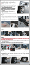
SAFETY INFORMATION
For your safety, read this manual thoroughly
before operating the EEWH312A Series Tire Changer
The EEWH312A Series Tire Changers are intended for use by properly trained automo-
tive technicians. The safety messages presented in this section and throughout the
manual are reminders to the operator to exercise extreme care when changing tires
with these products.
There are many variations in procedures, techniques, tools, and parts for changing
tires, as well as the skill of the individual doing the work. Because of the vast number
of wheel and tire applications and potential uses of the product, the manufacturer can-
not possibly anticipate or provide advice or safety messages to cover every situation.
It is the automotive technician’s responsibility to be knowledgeable of the wheels and
tires being changed. It is essential to use proper service methods and change tires in
an appropriate and acceptable manner that does not endanger your safety, the safety
of others in the work area or the equipment or vehicle being serviced.
It is assumed that, prior to using the EEWH312A Series Tire Changers, the operator
has a thorough understanding of the wheels and tires being changed. In addition, it is
assumed he has a thorough knowledge of the operation and safety features of the rack,
lift, or fl oor jack being utilized, and has the proper hand and power tools necessary to
service the vehicle in a safe manner.
Before using the EEWH312A Series Tire Changers, always refer to and follow the safety
messages and service procedures provided by the manufacturers of the equipment
being used and the vehicle being serviced.
IMPORTANT !! SAVE THESE INSTRUCTIONS -- DO NOT DISCARD !!

EEWH326A Tire Changer Operation Manual
- Page 6 -
Overinfl ated tires or tires mounted on the wrong sized rims can explode produc-
ing hazardous fl ying debris.
Read Operator’s Manual before using this Tire Changer.
Never mount tire on rim with different sized diameter.
Never exceed maximum infl ation pressure listed on tire sidewall.
Always use safety restraint arm to hold wheel in place while
infl ating.
Always use attached air hose to infl ate tires.
Exploding tires can cause death or serious injury.
Risk of electrical shock.
Do not operate equipment with a damaged power cord or if the
equipment has been dropped or damaged, until it has been
examined by a qualifi ed service person.
If an extension cord is necessary, a cord with a current rating equal
to or greater than that of the equipment should be used. Cords
rated for less current than the equipment can overheat.
Unplug equipment from electrical outlet when not in use. Never
use the cord to pull the plug from the outlet. Grasp plug and pull to
disconnect.
Do not expose the equipment to rain. Do not use on wet surfaces.
Plug unit into correct power supply.
Do not remove or bypass grounding pin.
Contact with high voltages can cause death or serious injury.
Risk of electrical shock. High voltages are present within the base unit.
There are no user serviceable items within the unit.
Service on the unit must be performed by qualifi ed personnel.
Do not open any part of the base cabinet.
Unplug the unit before servicing.
Contact with high voltages can cause death or serious injury.
SAFETY INSTRUCTIONS
IMPORTANT!! SAVE THESE INSTRUCTIONS

EEWH312A Tire Changer Operation Manual
- Page 7 -
Risk of crushing. Stand clear of bead breaker arm during operation.
Read and understand the operation instructions before using this
tire changer.
Become familiar with all controls before proceeding with operation.
Stand away from the bead breaker arm when in operation.
Apply air to breaker in bursts if necessary to control arm depth.
Keep all persons clear of tire changer.
Contact with moving parts could cause injury.
Risk of pinching or crushing hands and fi ngers when mounting and demounting.
Read and understand the operation instructions before using this
tire changer.
Keep hands and fi ngers clear of rim edge during demounting and
mounting process.
Keep hands and fi ngers clear of mount/demount head during opera-
tion.
Keep hands and other body parts away from moving surfaces.
Do not use tools other than those supplied with tire changer.
Do not bypass any safety features.
Use proper tire lubricate to prevent tire binding.
Contact with moving parts could cause injury.
Risk of eye injury.
Flying debris, dirt, and fl uids may be discharged during bead
seating and infl ation process.
Remove any debris from tire tread, wheel surfaces.
Remove excess tire lubricant before infl ating.
Wear approved safety glasses during mount and demount
procedures.
Debris, dirt, and fl uids can cause serious eye injury.
Risk of injury. Tools may break or slip if improperly used or maintained.
Read and understand the operation instructions before using this
tire changer.
Use only the mount-demount tire tool supplied with the tire changer.
Frequently inspect, clean, and lubricate (if recommended) where
designated.
Follow procedures when instructed in this manual.
Tools that break or slip can cause injury.
IMPORTANT !! SAVE THESE INSTRUCTIONS -- DO NOT DISCARD !!
Warning !
Warning !

EEWH326A Tire Changer Operation Manual
- Page 8 -
Tires and Rims that are not the same diameter are mismatched.
NEVER attempt to mount or infl ate any tire and rim that are mismatched.
ALWAYS check to see that tire and rim diameters are the same.
A mismatched tire and rim could explode causing death or serious personal injury
Over-pressurized tires can explode causing fl ying debris.
Read and understand Operator’s Manual before operating.
Keep bystanders away from work area.
ALWAYS wear Safety Goggles.
ALWAYS check to see that Tire and Rim diameters are the same.
NEVER attempt to mount or infl ate any Tire and Rim with different
diameters.
Inspect tires, NEVER infl ate tires that are damaged, rotten or worn.
NEVER infl ate ‘Split Rim Wheels’ on this tire changer, remove them and
use only an approved safety infl ation cage designed for this purpose.
Lock turntable Clamp on inside of rim before attempting to infl ate tire.
Use approved tire bead lubricant before removing or installing tire on
rim.
ALWAYS position the “Safety Restraint Arm” over the wheel to hold it
to the turntable while infl ating if so equipped.
If a tire explodes on this tire changer, STOP using it until the "Safety
Restraint Arm" has been replaced, which must be done even if no
damage is seen.
NEVER place head or body over a tire during infl ation process.
Use short bursts of air to seat tire beads, check tire air pressure
frequently. NEVER exceed tire manufacturer’s pressure limits.
NEVER attempt to bypass or alter the built in air pressure limiter. Only
infl ate tire with air hose supplied with tire changer. NEVER use shop
infl ation hose to infl ate a tire.
Tire Changer must be anchored to concrete fl oor if equipped with a
“Safety Restraint Arm”
Exploding Tires can cause serious injury.

EEWH312A Tire Changer Operation Manual
- Page 9 -
TABLE OF CONTENTS
SAFETY STATEMENTS Page 5-8
TABLE OF CONTENTS Page 9
1.0 INTRODUCTION Page 10
1.1 SPECIFICATIONS and FEATURES Page 10
1.2 NOMENCLATURE Page 10
1.3 DIMENSIONS OF THE MACHINE Page 12
1.4 STANDARD ACCESSORIES Page 12
1.5 OPTIONAL ACCESSORIES Page 13
1.6 GENERAL PRECAUTIONS Page 14
2.0 INSTALLATION Page 14
2.1 ELECTRIC INSTALLATION
(AIR-ELECTRIC MODELS) Page 14
2.2 BEAD BREAKER INSTALLATION Page 15
2.3 AIR INSTALLATION Page 15
3.0 CONTROLS Page 16
4.0 MOUNTING AND DEMOUNTING-PRECAUTIONS Page 17
4.1 DEMOUNTING TUBELESS TIRES Page 17
4.2 MOUNTING TUBELESS TIRES Page 20
4.3 INFLATING TUBELESS TIRES Page 21
5.0 DEMOUNTING TUBE TYPE TIRES Page 23
5.1 MOUNTING TUBE TYPE TIRES Page 23
5.2 INFLATING TUBE TYPE TIRES Page 24
6.0 MOUNTING/DEMOUNTING MOTORCYCLE TIRES Page 24
7.0 MAINTENANCE Page 25

EEWH326A Tire Changer Operation Manual
- Page 10 -
1.0 INTRODUCTION
Congratulations on purchasing the Snap-on EEWH312A
Series air, or air-electric tire changer. This tire changer
is designed for ease of operation, safe handling of rims,
reliability and speed. This combination of features means
more profi t and added versatility for your shop, enabling you
to work with aluminum or magnesium alloy wheels without
damaging customer’s rims. With a minimum of maintenance
and care your Snap-on EEWH312A Series Tire Changer will
provide many years of trouble-free operation.
Please read this manual thoroughly before operating the unit.
Instructions on use, maintenance and operational require-
ments of the machine are covered in this manual.
1.1 SPECIFICATIONS
Operation temperature range +41/+122 F (+5/50 C)
Air and Air-Electric tire changers for car, light commercial
vehicle and motorcycle tires designed for one-piece rims.
EEWH306A
Weight: EEWH306A 450 lbs (204 kg)
Air pressure required 110-170 psi (8-12 bar)
Bead breaker force 3300 lbs (kN 15)
Max. wheel diameter 40” (mm 1016)
Max. wheel width 12” (305mm)
Rim diameter outside locking 10”-18”(254-457mm)
Rim diameter inside locking 12”-20”(305-508mm)
Motorcycle wheels with adapters 15”-27”(381-584mm)
Motor 110 VAC 60Hz (air/electric models) 1 Hp (kw .75)
EEWH312A Series
Weight: EEWH312A 530 lbs (204 kg)
Air pressure required 110-170 psi (8-12 bar)
Bead breaker force 3400 lbs (kN 15)
Max. wheel diameter 40” (mm 1016)
Max. wheel width 12” (305mm)
Rim diameter outside locking 10”-20”(254-508mm)
Rim diameter inside locking 12”-22”(305-558mm)
Motorcycle wheels with adapters 15”-27”(381-686mm)
Motor 110 VAC 60Hz (air/electric models) 1 Hp (kw .75)
1.2 NOMENCLATURE
Before installing and using the Snap-on EEWH312A Series
Tire Changer it is suggested that you become familiar with
the nomenclature of the machine’s components.
1 Vertical slide
2 Swing arm
3 Swing Arm Adjustment knob
4 Lock lever
5 Mount/demount head
6 Tower or column
7 Turntable
8 Clamping Jaws
9 Bead breaker arm
10 Bead breaker blade
11 Bead breaker pads
12 Foot pedal controls
13 Infl ation gauge
14 Bead seater/infl ator pedal
15 Infl ation jets
16 Safety restraint arm (Standard Models Only)
17 Safety restraint positioning knob
(Standard Models Only)
18 Infl ation hose
19 Lube bottle
20 Mount/Demount Tool
21 Safety Restraint Arm Anti-rotation Lock
(Standard Models Only)
912
Figure 1

EEWH312A Tire Changer Operation Manual
- Page 11 -
TURNTABLE & CABINET FEATURES
EEWH312A &
SQUARE TURNTABLE PLATFORM - Provides easy access to
tires lower bead during the tire changing process.
INTEGRATED BEAD SEATING JETS - Air infl ation jets are
integrated into the turntable clamping jaws to insure full bead seating
force directly into the
tire cavity regardless of tire diameter.
TWIN CYLINDER CLAMPING POWER - Two 2.45” clamping
cylinders provide uniform clamping pressure throughout the stroke
(regardless of rim sizes) as well as providing 25% more clamping
power than most single clamping cylinder tire changers. Additionally
two smaller cylinders reduce the critical turntable to cabinet distance,
reducing the stress on the transmission.
WHEEL CLAMPS
UNIQUE SIX POINT CONTACT CLAMPS
Provide better gripping capability regardless of dirt and
moisture.
REDUCED ANGLE CLAMPS
Increases clamping contact area with rim insuring no slippage.
NYLON INSERT SOFT TOUCH CLAMPS
Single sided nylon insert in the clamping jaws provides non-
metal touch
in critical customer visible areas.
VALVE CORE/TIRE TOOL STORAGE
On tire changer storage area for valves, tools, caulk, etc.
IN-COMING AIR PRESSURE GAUGE
Ergonomically located air gauge allows easy monitoring of incoming
air pressure.
INTEGRATED PRESSURE LIMITER
Integrated safety pressure limiter stops air fl ow once tire pressure has
reached approx. 55 PSI preventing accidental tire over-infl ation.
MOUNT/DEMOUNT ARM ASSEMBLY
NON-SCRATCH NYLON INSERT - Integrated into the mount/
demount head is a replaceable scratch resistant nylon insert protect-
ing against accidental rim contact.
SAFETY RESTRAINT ARM (Standard Mod-
els IN, INA only)
TIRE/RIM ASSEMBLY RESTRAINT - Safety Restraint Arm
positively restrains tire and rim assembly to the tire machine during
the infl ation process reducing potential for injury caused by the
unlikely event of catastrophic tire or rim failure.
SIMPLE SWING ARM DESIGN - SRA arm easily swings to
the left when not in use allowing the technician to quickly and safely
perform the infl ation process without disrupting the tire changing
procedure.
GRAVITY LOCK - SRA lock mechanism operates without any
mechanical cam system eliminating the possibility of system deterio-
ration
or misadjustment from mechanical wear.
POSITIONING SAFETY INTERLOCK SWITCH - Integrated
switch insures that SRA arm is centered on the tire/rim assembly
before the infl ation process can begin.
ANTI-ROTATION LOCK - Prevents SRA from rotating during
infl ation process.
CONSTRUCTION DESIGNED FOR DURABILITY
RUST PROOF VALVES AND CYLINDERS - Critical bead
breaking cylinder is lined with rust-proof polyfi ber liner for years
of rust free operation. Non-lined cylinders will pit causing bead
breaker power loss.
LIFETIME LUBRICATED POLYMER VALVES - Critical foot
valves fabricated from glass/fi ber self lubricating material providing
years of maintenance free operation.
WATER SEPARATOR AND AUTOMATIC OILER - Lubricates
all air used for machine operation, does not lubricate air used for tire
infl ation, as do some competitive models.
HIGH TORQUE 1HP MOTOR - Industrial strength high torque
turntable drive motor eliminates tire remount stalling on low profi le
high performance tires (UL/CSA approved ).
5 YEAR TRANSMISSION WARRANTY - Designed for ex-
tremely heavy use the critical motor to turntable transmission linkage
carries a full fi ve (5) year replacement warranty.

EEWH326A Tire Changer Operation Manual
- Page 12 -
1.3 MACHINE DIMENSIONS - EEWH312A
926
Figure 2
1.4 STANDARD ACCESSORIES
87111 - Mount /Demount Tool (Fig.3)
294
Figure 3
Infl ation Gauge is mounted on the Infl ation Tank Column.
(Not shown)
Air Filter and Air Lubricator, (Fig.4)
539
Figure 4
Incoming Air Pressure Gauge
Located on the air fi lter and the air lubricator
Lubrication Bottle
Lubrication Applicator
Replacement Mount/Demount Head Inserts (4)

EEWH312A Tire Changer Operation Manual
- Page 13 -
1.5 OPTIONAL ACCESSORIES
87435 - Motorcycle Adapter- 4 required (Fig.5)
320
Figure 5
87436 - 8” Wheel Adapter- 4 required (Fig.5)
316
Figure 6
66735 - Bead Holding Clamp (Fig.7)
315
Figure 7

EEWH326A Tire Changer Operation Manual
- Page 14 -
1.6 GENERAL CAUTIONS
A. DURING THE USE AND MAINTENANCE OF THE MA-
CHINE IT IS MANDATORY TO COMPLY WITH ALL LAWS
AND REGULATIONS FOR ACCIDENT PREVENTION.
B. THE ELECTRICAL POWER SOURCE MUST HAVE A
GROUND CABLE AND THE GROUND CABLE OF THE
MACHINE MUST BE CONNECTED TO THE GROUND
CABLE OF THE POWER SOURCE.
C. BEFORE ANY MAINTENANCE OR REPAIRS ARE AC-
COMPLISHED THE MACHINE MUST BE DISCONNECTED
FROM THE AIR AND ELECTRICAL SUPPLY.
D. NEVER WEAR TIES, CHAINS OR OTHER LOOSE
ARTICLES WHEN USING, MAINTAINING OR REPAIR-
ING THE MACHINE. LONG HAIR IS ALSO DANGEROUS
AND SHOULD BE KEPT UNDER A HAT. THE USER MUST
WEAR PROPER SAFETY ATTIRE - GLOVES, SAFETY
SHOES AND GLASSES.
2.0 INSTALLATION
Your new Snap-on EEWH312A Series Tire Changer requires
a simple installation procedure requiring only a few moments.
Follow these instructions carefully to insure proper and safe
operation.
The Tire Changer is delivered mounted to a wooden skid.
Remove tire changer from its mounts carefully, taking care
to avoid any back strain.
Place Changer where proper operation will be unobstructed to
all sides. Install the machine in a covered and dry place.
2.0.1 Anchoring
Once placed in the desired location the tire changer must be
bolted to the fl oor using only the rear two mounting holes.
Mounting anchors are provided with those machines with a
Safety Restraint Arm.
Tire Changer should be anchored to concrete
fl oor for increased safety.
2.1 ELECTRICAL INSTALLATION
(air-electric models)
BUILDING ELECTRICAL INSTALLATION MUST BE
MADE BY A LICENSED ELECTRICIAN.
Check that the electrical specifi cations of the power source
are the same of the machine. The machine uses 110v, 60
hz, single phase 20 amp source. Electric specifi cations are
clearly marked on a label at the rear of the machine.
FAILURE TO PROVIDE PROPER ELECTRICAL SUP-
PLY AND GROUNDING WILL CREATE A SHOCK
HAZARD TO THE OPERATOR.
540

EEWH312A Tire Changer Operation Manual
- Page 15 -
2.2 BEAD BREAKER INSTALLATION
The side mounted Bead Breaker is shipped from the factory
dismounted for a more compact shipping package.
A. Cut the plastic tie strap which secures the Breaker Arm
to the cabinet pivot.
B. Remove the “C” clip from the top of the pivot pin, slip the
pin out of the hole.
C. Place the Breaker Arm into position and insert the pivot
pin through the top and bottom holes.
D. Replace the “C” clip retainer onto the pivot pin.
E. Locate the spring located at the rear of the pivot mount.
Place the free end of the spring onto the “ear” located on the
Breaker Arm just forward of the pivot.
HINT: You may tie a small rope or cord onto the free end
of the spring, run the cord through the hole. Pull the spring
end toward the ear and loop free end over.
2.3 AIR INSTALLATION
THE AIR INSTALLATION MUST BE MADE ONLY BY
QUALIFIED PERSONNEL.
EXCESSIVE AIR PRESSURE CAN SERIOUSLY IN-
JURE PERSONNEL AND DAMAGE THE MACHINE.
Ensure that the line pressure is within the limits required by
the machine. If the pressure exceeds 170 psi (12 bar) it is
mandatory to install a pressure regulator before the air inlet
of the machine.
If the air pressure is lower than the minimum required of
110 psi (8 bar) the clamping power of the turntable and the
bead breaker power may be insuffi cient for certain tires and
substantially reduces tire changer performance.
It is suggested that the air supply be equipped with a water
separator/dryer type modification for maximum perfor-
mance.
After ensuring all the above proceed as follows:
A. Connect the machine to the air supply with a rubber hose
(rated for the pressure) with an internal diameter of no less
than 1/2” (12.5mm).
WARNING!
BEFORE CONNECTING THE
MACHINE TO THE AIR SUP-
PLY BE SURE ALL PERSON-
NEL ARE CLEAR OF THE MA-
CHINE AND NO ITEMS ARE
LEFT ON THE TURNTABLE.
B. It is recommended that an air valve shut-off be installed
between the shop air supply and the tire changer in case of
air line or fi lter failure.
C. Should you install any optional accessories, please refer
to the relevant instructions.
D. Ensure the functional ability of the air lubricator by ensur-
ing that the glass site bowl is fi lled with air lubricant.

EEWH326A Tire Changer Operation Manual
- Page 16 -
3.0 CONTROLS
927
Figure 8
Before operating the machine, take the time to familiarize
yourself with the operation and function of all the controls.
A Press down and release the fi rst pedal (1) from the left:
the jaws of the turntable will retract. Do it again: the jaws
will expand. If you press the pedal prior to the end of
the stroke and release, the jaws may be stopped in any
position.
B Open the bead breaker arm. Press down and hold the
second pedal (2) from the left: by doing this you operate
the bead breaker blade and the arm will move towards
the machine. Release the pedal: the bead breaker blade
will retract.
WARNING!
WATCH YOUR FINGERS AND LEGS!
541a 542a
C Press down the fi rst pedal (3) from the right: the turntable
turns clockwise. Placing your foot under the pedal and
lift, the turntable turns counterclockwise.
D Lower the Lock Lever (4 ) to unlock the vertical slide, lift
the Lock Lever to lock.
E Turn Swing Arm Adjustment Knob (5) for positioning
mount/demount head slightly away from rim diameter
F Press bead-seater pedal on left side of the machine (6
) half way down: air will come out from infl ation hose
end.
G Press bead-seater pedal (6) all the way down swiftly to
get air blast from the infl ator jets in the clamping jaws.
Air simultaneously comes out of infl ator hose.
ATTENTION!
WHEN OPERATING THE BEAD SEATER IT IS MANDATO-
RY TO WEAR SAFETY GLASSES TO PROTECT EYES.
Standard Models ( IN, INA)
H Safety Restraint Arm (7) swings to center of the turn-
table.
I Lift upward on the restraint positioning knob (8) to posi-
tion over tire/wheel assembly for infl ation, at the same
time push down on the Anti-rotation Lock Arm to release
lock. (9) You may now swing the safety restraint arm to
position on the center of the wheel. Lower the restraint
until the rubber pad on the restraint disc is resting on
the rim center. The SRA is a gravity lock which will
automatically lock if any force other than the restraint
position knob is lifted. You are now ready for the infl ation
process.
NOTE: the air supply will not function until the safety
arm is centered over the turntable.
9

EEWH312A Tire Changer Operation Manual
- Page 17 -
4.0 MOUNTING AND DEMOUNTING PRECAUTIONS
IMPORTANT!
BEFORE MOUNTING A TIRE ON A RIM, PAY ATTENTION
TO THE FOLLOWING:
A. THE RIM MUST BE CLEAN AND IN GOOD CONDI-
TION: IF NECESSARY CLEAN IT AFTER REMOVING
ALL WHEEL-WEIGHTS INCLUDING ‘TAPE WEIGHTS’
INSIDE THE RIM.
B. THE TIRE MUST BE CLEAN AND DRY, WITHOUT ANY
DAMAGE TO THE BEAD.
C. REPLACE THE RUBBER VALVE STEM WITH A NEW
ONE OR REPLACE THE ‘O’ RING IF THE VALVE STEM
IS MADE OF METAL.
D. IF THE TIRE REQUIRES A TUBE, MAKE SURE THE
TUBE IS DRY AND IN GOOD CONDITION.
E. LUBRICATION IS NECESSARY TO MOUNT THE
TIRE CORRECTLY AND GET A PROPER CENTERING.
BE SURE YOU ARE USING APPROVED LUBRICANT
ONLY.
F. MAKE SURE THE TIRE IS THE CORRECT SIZE FOR
THE RIM.
4.1 DEMOUNTING TUBELESS TIRES
A. Remove all wheel-weights from the rim. Remove the valve
stem or valve stem core and defl ate the tire (Fig.11).
535a
Fig.11
B. Break both beads.
Hold open the Bead Breaker, roll the tire/rim into the Breaker
area (Fig. 12). Ensure that the Tire/rim assembly is against
the rubber breaker pads on the side of the machine. Make
certain that the bead breaker blade is not over the top of any
portion of the rim. Now activate the bead breaker pedal. As
soon as the bead dislodges from the rim, release the breaker
foot pedal. It may be necessary to rotate the tire 90 degrees
and repeat the above procedure to dislodge all beads.
Pay extra attention during this operation as it is easy to mis-
takenly keep your foot on the bead breaking pedal too long.
This could potentially result in bead or rim damage (Fig.12)
536
Fig.12
NOTICE !
ON RUN FLAT DESIGN TIRES WITH THE OPTIONAL LOW
PRESSURE SENSOR INSTALLED, BREAK THE BEAD AT
90 DEGREES OFFSET FROM THE VALVE STEM. DAM-
AGE TO THE WHEEL AND/OR SENSOR WILL RESULT
IF THE BEAD IS BROKEN AT ANY OTHER POINT ON
THE RIM.
C. Set the rim clamps to the proper position: retract clamps
to clamp the wheel from the outside and expand clamps to
clamp from the inside.
When clamping small wheels (14” or smaller) from the out-
side, set the clamps at a diameter nearly equal to the rim
diameter, before placing the wheel on the clamps. This will
help avoid the possibility of pinching the tire as the clamps
retract.
NOTICE !
TO MINIMIZE THE RISK OF SCRATCHING ALLOY OR
CLEAR COATED RIMS, THESE RIMS SHOULD BE
CLAMPED FROM THE OUTSIDE.

EEWH326A Tire Changer Operation Manual
- Page 18 -
D. Liberally lubricate both beads. Place the wheel WITH
DROP CENTER UP (Fig.13a) on the turntable, and clamp in
position. Hold the tire and wheel down while clamping.
331
Fig.13 Fig. 13a
E. Gently position the mount/demount head in contact with
rim edge, now manually push the lock lever up and lock it
into place. The tool automatically moves vertically up and
away from the rim edge. Turn the swing arm adjustment
knob until the mount/demount head moves horizontally away
from the rim fl ange by approximately 1/16” (2mm): this is
necessary to avoid any rim contact during the changing
process. (Fig.14).
332
Fig.14
NOTE:
EVERY MACHINE IS EQUIPPED WITH SEVERAL RE-
PLACEMENT PLASTIC INSERTS (INSIDE STANDARD
EQUIPMENT PACK). THE PLASTIC INSERTS WILL
HELP AVOID DAMAGE FROM ACCIDENTAL CONTACT
BETWEEN THE MOUNT/DEMOUNT HEAD AND THE RIM.
THE PLASTIC INSERTS WILL NEED TO BE PERIODI-
CALLY REPLACED.
MAINTENANCE NOTE:
IF THE MOUNT/DEMOUNT HEAD NYLON INSERTS ARE
WEARING OUT PREMATURELY, THE CAUSE IS THE
OPERATORS FAILURE TO CORRECTLY SET THE SWING
ARM ADJUSTMENT KNOB, CAUSING THE INSERT TO
INCORRECTLY CONTACT THE RIM.
NOTE:
ONCE THE MOUNT/DEMOUNT HEAD IS POSITIONED
PROPERLY, IDENTICAL WHEELS MAY BE CHANGED
WITHOUT HAVING TO RESET THE HEAD.
F. Insert the mount/demount tool under the bead and over
the support of the mount/demount head. Lift the bead onto
the mount/demount head. To make this operation easier,
insure that the bead of the tire, directly across from the mount/
demount head, is in the drop center of the wheel. Push the
tire into the drop center with your hand or bead depressor
tool if necessary.
If desired, the mount/demount tool can be removed after lift-
ing the bead onto the mount/demount head (Fig.15), or you
may remove the tool after the bead has been removed.
1/16”

EEWH312A Tire Changer Operation Manual
- Page 19 -
333
Fig.15
G. Rotate the turntable clockwise (pedal down) and, at the
same time, push down on the tire sidewall to move the bead
into the drop center of the rim (Fig.16).
334
Fig.16
H. Repeat the process for removing the lower bead.
This time, lift the bead opposite to the mount/demount head
to keep it in the drop center (Fig.17).
Move the swing arm aside and remove the tire.
335
Fig.17

EEWH326A Tire Changer Operation Manual
- Page 20 -
4.2 MOUNTING TUBELESS TIRES
A. Clean entire rim surface (Fig.18).
336
Fig.18
Liberally lubricate both beads of the tire with approved tire
lubricant (Fig.19).
337
Fig.19
NOTICE!
THESE LUBRICATION OPERATIONS ARE NECESSARY
TO MOUNT THE TIRE CORRECTLY AND GET A PROPER
CENTERING ON THE RIM. BE SURE YOU ARE USING
APPROVED LUBRICANT ONLY.
DANGER!! Keep hands
and fingers clear of
mount-demount head
during operation.
/